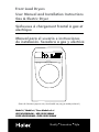
Haier CHDE5000AW User Manual and Installation Instructions
- Catégorie
- Sèche-linge électriques
- Taper
- User Manual and Installation Instructions
Ce manuel convient également à

User Manual and Installation Instructions
Gas & Electric Dryer
Sécheuses à chargement frontal à gaz et
électrique
Manual para el usuario e instrucciones
de instalación. Secadora a gas y eléctrica
Model #/ Modéle #/ Para Modelo de #
HDE/HDG5000AW ; HDE/HDG5300AW
Quality
■
Innovation
■
Style
(Picture for illustration purposes only. Actual model may vary per model purchased.)
Front Load Dryers
CHDE/HDG5000AW ; CHDE/HDG5300AW

1
English
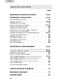
PAGE
IMPORTANT SAFETY INSTRUCTIONS.......................................2-4
INSTALLATION INSTRUCTIONS..............................................5-24
Tools and Materials Required ............................................................ 5
Electrical Requirements ..................................................................5-6
Unpacking Your Dryer ..................................................................... 6
Exhaust System Requirements ........................................................7-8
Gas Supply Requirements ................................................................ 9
Location of Your Dryer ...................................................................10
Location of Your Dryer in a Closet....................................................11
Manufactured (Mobile) Home Instruction .........................................12
Procedure for Reversing the Door............................................... 13-17
Changing the Drum Light ................................................................18
Electrical Installation ......................................................................19
3-Wire Cord Connections ..............................................................20
4-Wire Cord Connections ..............................................................21
Gas Connections ..........................................................................22
Replacement Parts .........................................................................24
OPERATING INSTRUCTIONS ............................................... 25-38
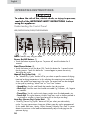
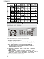
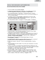
Understanding the Control Panel
(HDE/HDG5300AW,CHDE/HDG5300AW)
....... 25-27
Understanding the Control Panel 27-29
Preparations before Drying .............................................................30
Load clothes into Dryer ...................................................................31
Auto Dry Cycle
..........................
32-33
Auto Dry Cycle 34
Manual Dry Cycle 35
Manual Dry Cycle 36
Other Features...............................................................................37
Normal Operating Sounds..............................................................38
CARE AND CLEANING GUIDE
.......................................................38
TROUBLESHOOTING.................................................................. 39
LIMITED WARRANTY .................................................................40
TABLE OF CONTENTS
(HDE/HDG5000AW,CHDE/CHDG5000AW)
.......
(HDE/HDG5300AW,CHDE/CHDG5300AW)
(HDE/HDG5000AW,CHDE/CHDG5000AW)
(HDE/HDG5300AW,CHDE/CHDG5300AW)
(HDE/HDG5300AW,CHDE/HDG5000AW)
..................................
..............................
..............................


English
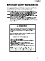
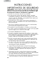
WARNING - To reduce the risk of fire, electric shock, or
injury to persons when using your appliance, follow the
basic precautions, including the following:
1. Read all of the instructions before using this appliance.
2. Don’t dry articles that have been previously cleaned in, washed in,
soaked in, or spotted with gasoline, dry clean solvents or other
flammable explosive sub stains as they give off vapors which could
ignite or explode.
3. Do not allow children to play on or in the appliance. Close
supervision of children is necessary when the appliance is used near
children.
4. Before the appliance is removed from service or discarded, remove
the door to the drying compartment.
5. Do not reach into the appliance if the drum is moving.
6. Do not install or store this appliance where it will be exposed to
water and/or to the weather.
7. Do not tamper with controls.
8. Do not repair or replace any part of the appliance or attempt any
servicing unless specifically recommended in the user-repair
instructions that you understand and have skills to carry out.
9. Do not use fabric softeners or products to eliminate static unless
recommended by the manufacturers of the fabric softener or
product.
10. Do not use heat to dry articles or products to eliminate static unless
recommended by the manufacturers of the fabric softener or
product.
11. Clean lint screen before or after each load.
12. Keep area around the exhaust opening and adjacent surrounding
areas free from the accumulation of lint, dust and dirt.
13. Keep the dryer area clear and free from items that would obstruct
the flow of combustion and ventilation air through the louvered panel
located on the rear of the dryer.
14. The interior of the appliance and the exhaust duct should be cleaned
periodically by qualified service personnel.
3
IMPORTANT SAFETY
INSTRUCTIONS

English
4
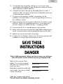
Thank you for using our Haier
product. This easy-to-use manual
will guide you in getting the best
use of your dryer.
Remember to record the model and
serial number. They are on a label
in back of the dryer.
Model number
Serial number
Date of purchase
Staple your receipt to your manual.
You will need it to obtain warranty service.
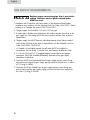
15. Do not place items exposed to cooking oils in your dryer. Items
contaminated with cooking oil may contribute to a chemical reaction
than could cause a load to catch fire.
16. If material has been used with any flammable liquids or solids, it
should not used in the dryer until all traces of flammable liquids and
its fumes have been removed.
17. This dryer must be properly installed in accordance with the
installation instructions before it is used. See grounding instructions in
the installations sections.
18. Proper grounding must be ensured to reduce the risk of electric shock
and force. Check with a qualified electrician or service personnel if
you are in doubt as to whether the dryer is properly grounded.
19. Use the dryer only for its intended purpose: drying clothes.
20. Always disconnect dryer from electrical supply before attempting any
service. Disconnect power cord by grasping the plug, not the cord.
21. Replace worn power cord and/or loose plugs.
22. To reduce the risk of electric shock or fire, do not use extension cords
or adapters to connect dryer electrical power source.
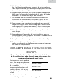
Risk of child entrapment. Before you throw away your old dryer,
take off the door so that children may not get trapped inside.
SAVE THESE
INSTRUCTIONS
DANGER

5
WARNING
Risk of Fire:
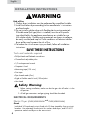
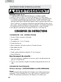
Tools and materials required
• Phillips-Head and flathead screwdrivers
• Channel-lock adjustable pilers
• 1/2-inch open-end wrench
• Carpenter’s level
• Measuring tape (12ft. min.)
• Duct tape
• Pipe thread sealer (Gas)
• Rigid or flexible metal 4 inch (102cm) duct
• Vent hood
Safety Warning:
1. Before starting installation, make sure that the gas shut off valve is in the
off position.
2. All old gas connectors and gas piping should be discarded.
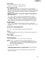
ELECTRICAL REQUIREMENTS
Electric Dryer:
(CHDE/HDE5000AW
and
CHDE/HDE5300AW)
Circuit
Individual 30 Amp branch circuit fused with 30 Amp time-delay fuses or circuit
breakers. Use seperately fused circuits for washers and dryers, and DO NOT
operate a washer and dryer on the same circuit.
INSTALLATION INSTRUCTIONS
English
1.Clothes dryer installation must be performed by a qualified installer.
2.Install the clothes dryer according to the manufacturer’s instructions
and local codes.
3.Do not install a clothes dryer with flexible plastic venting materials.
If flexible metal (foil type) duct is installed,it must be of a specific
type identified by the appliance manufacturer as suitable for use
with clothes dryers. Flexible venting materials are known to collapse,
be easily crushed,and trap lint.These conditions will obstruct clothes
dryer airflow and increase the risk of fire.
4.To reduce the risk of severe injury or death, follow all installation
instructions.
SAVE THESE INSTRUCTIONS

English
6
Power Supply
3 or 4 wire, 120/240 Volt, 1 Phase, 60Hz, AC
(Canada - 120/240 Volt, 1 Phase, 60 Hz, AC)
Power Supply Cord Kit
(Not supplied when sold in US. Must be purchased to meet local electrical
codes.) The dryer MUST employ a 3-conductor power supply cord NEMA 10-30
Type SRDT rated at 240 Volt AC minimum, 30 Amp, with 3 open end spade lug
connectors with upturned ends or closed loop connectors and marked for use
with clothes dryers.
(When sold in Canada - 4-wire power supply cord provided and
attached on dryer)
Dryers being installed in a manufactured (mobile) home MUST employ a
4-wire power supply cord NEMA 14-30 type SRDT or ST (as required) rated
to 240 Volt AC minimum, 30 Amp, with 4 open-end spade lug connectors
with upturned ends or closed loop connectors and marked for use with clothes
dryers. See Electrical Connections for more information on a 4-wire system.
Outlet Receptacle
NEMA 10-30R receptacle should be located so the power supply cord is
accessible when the dryer is in the installed position. (Canada - NEMA 14-30R
receptacle)
ELECTRICAL REQUIREMENTS
Gas Dryer: (CHDG/HDG5000AW and CHDG/HDG5300AW)
Circuit
Individual 15 Amp branch circuit fused with 15-Amp maximum time delay fuse
or circuit breakers.
Power Supply
3 wire, 120 Volt, 1 Phase, 60Hz, AC
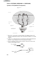
Power Supply Cord
The dryer is equipped with a 120 Volt 3-wire power supply cord.
NOTE: This dryer is equipped with a three-prong grounding plug for your
protection against shock hazard and should be plugged into a properly
grounded three-prong receptacle. Do not under any circumstance cut or
remove grounding prong from plug.
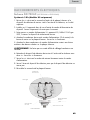
Unpacking Your Dryer
1. Remove all packaging material. This includes the foam base and all adhesive
tape holding the dryer accessories inside and outside.
2. Inspect and remove any remains of packaging, tape or printed materials
before using the dryer.

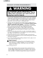
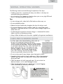
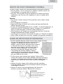
The following are specific requirements for
proper and safe operation of your dryer. Failure
to follow these instructions can create excessive
drying times and fire hazards.
1. Do not use plastic flexible duct to exhaust the dryer. Excessive lint can build up
inside exhaust system and create a fire hazard and restrict air flow. Restricted
air flow will increase drying time. If your present system is made up of plastic
duct or metal foil duct, replace it with a rigid or flexible metal duct. Ensure
present duct is free of any lint prior to installing dryer duct.
2.
The dryer shall not be exhausted into a chimney, a wall, a ceiling, an attic, a
crawl space, or a concealed space of a building;
The dryer exhaust system
MUST be
exhausted to the outdoors. If the dryer is not exhausted
outdoors, some
fine lint will be expelled into the laundry area. An accumulation
of lint in any
area of the home can create a health and fire hazard.
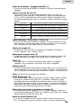
3. Exceeding the length of duct pipe or number of elbows allowed in the
“Maximum Length” chart can cause an accumulation of lint in the exhaust
system. Plugging the system could create a fire hazard, as well as increase
drying times.
4. Do not screen the exhaust ends of the vent system. Lint can become caught in
the screen, increasing drying time. Use an approved vent hood to terminate the
duct outdoors, and seal all joints with duct tape.
5. All male duct pipe fittings must be installed downstream with the flow of air.
6. The duct shall not be assembled with screws or other fastening means that extend
into the duct and catch lint.
7. Do not allow combustible material (clothing, draperies/curtains, paper, etc.) to
come in contact with exhaust system.
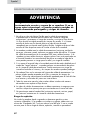
Explosion hazard:
Do not install the dryer where gasoline or other flammables are kept or
stored. If the dryer is installed in a garage, it must be a minimum of 18
inches (45.7cm) above the floor. Failure to do so can result in death,
explosion, fire or burns.
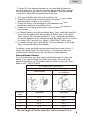
Exhaust Requirements:
Use only rigid or flexible metal duct and
approved vent hood which has a
swing-out
damper hat open when the dryer is
in operation. When the dryer
stops, the dampers automatically close to prevent
drafts
and the entrance of
insects and rodents. To avoid restricting the outlet,
WARNING
EXHAUST SYSTEM REQUIREMENTS
English
7
maintain a minimum of

clearance between the vent hood
and the ground or
any other obstruction. The vent flap should be able to move
freely, although
vertical orientation of the exhaust system is acceptable. Certain
extenuating
circumstances could affect the performance of the dryer:
1. Only rigid or flexible metal duct work should be used.
2. Venting vertically through a roof may expose the exhaust
system to down
drafts causing an increase in vent restriction.
3. Running the exhaust system through an uninsulatedarea may
cause
condensation and faster accumulation of lint.
4. Compression of crimping of the exhaust system will cause
an increase in
vent restriction.
The exhaust system should be inspected and cleaned a minimum of every 12
months with normal usage. The more the dryer is used the more often you
should check the exhaust system and vent hood for proper operation.
Side and Bottom Exhaust
For your convenience, your dryer can be exhausted through the side or the
bottom. If you need to change the exhaust on the dryer to the side or the
bottom of the cabinet, you will need to order the exhaust kit from your Haier
dealer or call 1- 800-313-8495
English
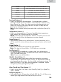
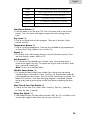
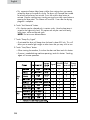
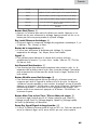
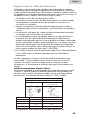
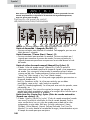
RECOMMENDED MAXIMUMM
Exhaust Hood Types
Recommended
Use only for short
run installations
No. of 90º
elbows
Rigid Metal Rigid Metal
0 90 ft. 60 ft.
1 60 ft. 45 ft.
2 45 ft. 35 ft.
3 35 ft. 25 ft.
12 inches (30.5cm)
The total length of flexible metal duct shall not exceed 2.4 m.
5. In Canada, that only those foil-type flexible ducts, if any, specifically identified
for use with the appliance by the manufacturer shall be used. In the United
States, that only those foil-type flexible ducts, if any, specifically identified for
use with the appliance by the manufacturer and that comply with the UL Outline
for Clothes Dryer Transition Duct, Subject 2158A (2006), shall be used.
6. In Canada, that the exhaust duct shall be 102 mm in diameter. In the United
States, the required exhaust duct diameter.
8

GAS SUPPLY REQUIREMENTS
English English
9
WARNING
ADVERTENCIA
ADVERTENCIA
ADVERTISSMENT
PRECAUCIÓN
PRECAUCIÓN PRECAUCIÓN
ATTENTION
CAUTION
CAUTION
Replace copper connecting pipe that is not plastic
coated. Stainless steel or plastic-coated brass
MUST be used.
1. Installation MUST conform with local codes. In the absence of local codes,
installation must conform with the National Fuel Gas Code, ANSI Z223.1 (latest
edition) or in Canada, the current CAN/CGA B149.1
2.
The gas supply line should be 1/2 inch (1.27cm) pipe.
3.
If codes allow, flexible metal tubing may be used to connect your dryer to the
gas supply line. The tubing MUST be constructed of stainless steel or plastic-
coated brass.
4.
The gas supply line MUST have an individual manual shutoff valve installed
within 6 feet (183cm) of the dryer in accordance with the National Fuel Gas
Code, ANSI Z223.1/NFPA 54.
In Canada, an individual manual shut-off valve MUST be installed in
accordance with the B149.1, Natural Gas and Propane Installation Code.
5. A 1/8 inch (0.32cm) N.P.T. plugged tapping, accessible for test gauge
connection, MUST be installed immediately upstream of the gas supply
connection to the dryer.
6. The dryer MUST be disconnected from the gas supply piping system during
any pressure testing of the gas supply piping system at test pressures in excess
of 1/2 psig (3.45kPa).
7.
The dryer MUST be isolated from the gas supply piping system during any
pressure testing of the gas supply piping system at test pressures equal to or
less than 1/2 psig (3.45 kPa).

English
10
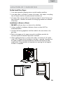
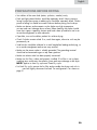
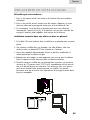
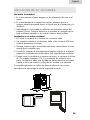
Do Not Install Your Dryer:
1. In an area exposed to dripping water or outside weather conditions.
2. In an area where it will come in contact with curtains, thick carpet, or anything
that will obstruct the flow of combustion and ventilation air.
3. On carpet, floor must be solid with a maximum slope of 1inch (2.54 cm). Any
floor unevenness should be corrected with leveling legs located on the bottom
of the dryer.
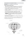
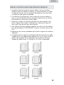
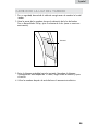
Installation in Alcove or Closet:
1. DO NOT install your dryer in a closet with a solid door.
2. A dryer installed in a bedroom, bathroom, alcove or closet MUST be
exhausted outdoors.
3. No other fuel burning appliance shall be installed in the same closet as the
gas dryer.
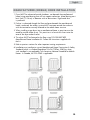
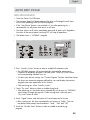
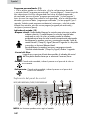
4. Refer to the images on this page to ensure the installation provides the
minimum amount of clearance required for ventilation.
5. When installing the dryer in a closet with a door, a minimum of 120 square
inches (774.2 square cm) of ventilation in the door is required. Openings must
be equally divided at the top and bottom of the door and airflow must be
unobstructed. A louvered door with equivalent air openings for the length of
the door is acceptable.
LOCATION OF YOUR DRYER
8
2
5
m
m
6
8
6
m
m
1010mm
1295mm(51”)
960mm(37-13/16“)
39-3/4”
2
7
”
3
2
-
1
/
2
”

English
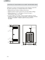
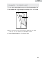
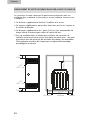
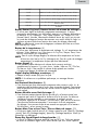
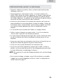
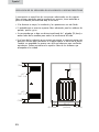
Following are instructions concerning and the minimum clearances required for
any closet, recessed area, or customized under-counter installation:
• Additional distances facilitate installation and servicing.
• Addtional clearances might be required for wall, door and floor moldings.
• Additional distances of 1 in. (25.4mm) on all sides of the dryer is
recommended to reduce noise transfer.
• For closet installation with a door, minimum ventilation openings in the top
and bottom of the door are required. Louvered doors with equivalent ventilation
openings are acceptable. Companion appliance spacing should be
considered.
LOCATION OF YOUR DRYER IN A CLOSET OR RECESSED AREA
11
32.5"
1 5 "
1
"
0
"
( 5.4mm )
2
( 0 mm )(8 25m m)
( 3
8
.1
mm)
3"
(76mm)
3"
(76mm)
60"
2
( )
387.1cm
2
60"
2
( )
387.1cm
2

English
12
1. Dryer MUST be exhausted outside (outdoors, not beneath the manufactured
home) using metal ducting that will not support combustion. Metal ducting must
be 4 inch (10.16 cm) in diameter with no obstructions. Rigid metal duct
is preferred.
2. If dryer is exhausted through the floor and area beneath the manufactured
home is enclosed, the exhaust system MUST terminate outside the enclosure
with the termination securely fastened to the mobile home structure.
3. When installing a gas dryer into a manufactured home, a provision must be
made for outside make up air. This provision is to be not less than twice the
area of the dryer exhaust outlet.
4. This dryer MUST be fastened to the floor using P/N 0030807899
Manufactured Home Installation Kit. Follow the instructions supplied with
the kit.
5. Refer to previous sections for other important venting requirements.
6. Installation must conform to current Manufactured Home Construction & Safety
Standard (which is a Federal Regulation Title 24 CFR-Part 32-80) or when
such standard is not applicable, with American National Standard for Mobile
Homes. In Canada, the CSA Z240 is applicable.
MANUFACTURED (MOBILE) HOME INSTALLATION

English
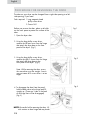
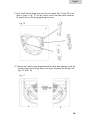
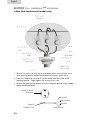
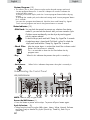
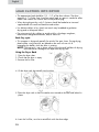
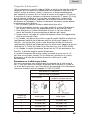
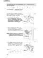
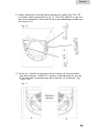
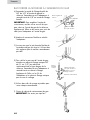
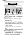
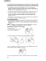
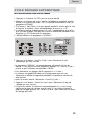
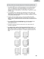
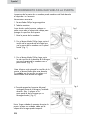
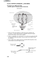
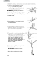
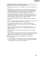
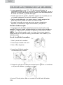
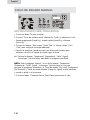
Before you reverse the door, place a soft cloth
on the work space to protect the surface of the
door.
1. Open the dryer door.
2. Using the long phillip screw driver,
remove the left one screw from the hinge
that attach the dryer door to the front
panel of the dryer. (Fig 1)
3. Using the long phillip screw driver,
remove the right 2 screws from the hinge
that attach the dryer door to the
front panel of the dryer. (Fig 2)
Note: While removing the door screws,
the screwdriver must be straight. Screws
may not come off if screw driver is at an
angle.
4. To disengage the door from the panel,
hold the door close to the hinge and lift
straight up. (There are 3 tabs in the back
of the hinge that will be disengaged).
(Fig 3)
The door on your dryer can be changed from a right-side opening to a left-
side opening, if you need.
Tools required: 1. Long magnetic head
phillip screw driver
2. Power Drill
13
Fig 1
Fig 2
Fig 3
NOTE: Be careful while removing the door. Lift
with caution or door hinge tab may break.
PROCEDURE FOR REVERSING THE DOOR

English
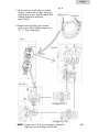
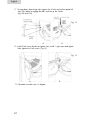
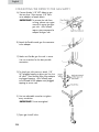
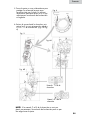
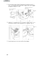
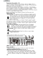
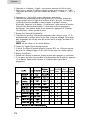
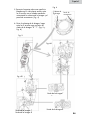
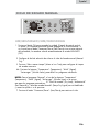
5. Lay the door on a soft surface to protect
the door surface with the glass facing up,
remove the 8 screws using the power drill
holding hinge cover and strike
panel. (Fig 4)
6. Remove the hinge cover, then remove
the 8 screws which hold the hinge knots
“B” “T”. (Fig 5 and Fig 6)
1413
Fig. 5
Fig. 6B
Fig. 6A
Fig. 4
Strike Panel
Hinge Cover
NOTE: If hinge knots (T & B) are not properly placed the
hinge cover may not align with the door.

English
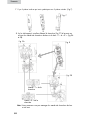
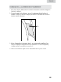
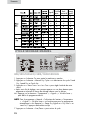
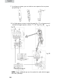
7. There are 3 parts included which are symmetrical to the 3 removed parts
(Fig 7)
1615
A
Fig. 7
Fig. 9A
B
C
8. On the opposite side first install the hinge (Fig 7C) to the door using Top
and Bottom Hinge Knot “T” and “B”. (Fig 9A and 9B)
Fig. 8
Fig. 9B
Note: Be careful not to get the top and bottom hinge knots mixed up.

English
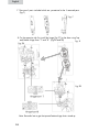
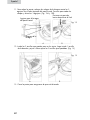
10. Remove the 3 plastic plugs located outside the dryer door opening. Install the
3 plastic plugs into the hinge holes in the dryer front panel on the right side.
(Fig 11A and 11B)
9. Now install both the hinge cover and the strike panel (Fig. 7A and 7B) to the
door as shown in Fig. 10. Use the same 8 screws that were earlier removed
Be carefull not to strip during tightening the screws.
1615
Fig. 10
B
A
Fig. 11

11. To hang door, place hinge tab’s against the 3 holes on the front panel left
side. Press down to engage the tab’s and line up the 3 holes.
(Fig 12A and 12B).
12. Install 2 left screws but do not tighten, then install 1 right screw and tighten.
Now tighten the 2 left screws. (Fig 13)
13. Close door to make sure it is aligned.
English
17
A
A
B
B
Fig. 12
Fig. 13

English
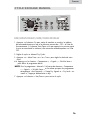
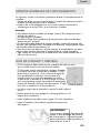
1. For your safety, please unplug the power cord before changing the drum light.
2. Open the dryer door, find the location of the drum light. Using a phillip head
screw driver remove the light cover (as shown below).
3. Remove the bulb by turning it counterclockwise. Replace the bulb with a
10-watt lamp only, then install the cover and tighten the screw.
4. Use your dryer after plugging it in the electrical socket.
CHANGING THE DRUM LIGHT
18
Screw

English
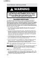
The following are specific requirements for proper
and safe electrical installation of your dryer.
Failure to follow these instructions can create
electrical shock and/or fire hazard.
WARNING
1. This appliance must be properly grounded. Electrical shock can result if the
dryer is not properly grounded. Follow the instructions in this manual for
proper grounding.
2. Do not use an extension cord with this dryer. Some extension cords are not
designed to withstand the amounts of electrical current this dryer utilizes and
can melt, creating electric shock and/or fire hazard. Locate the dryer within
reach of the receptacle for the length power cord to be purchased, allowing
some slack in the cord. Refer to the electrical requirements in this manual for
the proper power cord to be purchased.
3. A UL approved strain relief must be installed onto power cord. If the strain
relief is not attached, the cord can be pulled out of the dryer and can be cut
by any movement of the cord, resulting in electrical shock.
4. Do not use an aluminum wire receptacle with copper-wired power cord and
plug (or vice versa ). A chemical reaction occurs between copper and
aluminum and can cause electrical shorts. The proper wiring and receptacle
is a copper-wired power cord with a copper-wired receptacle.
NOTE: Dryers operating on 208 Volt power supply will have longer drying times
than operation on 240 Volt power supply.
Improper connection of the equipment grounding conductor can
result in a risk of electrical shock. Check with a licensed
electrician if you are in doubt as to whether the appliance is
properly grounded.
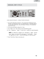
1. Gas dryers are equipped with a factory installed three-prong 15 Amps ~120
Volts (grounding) plug for your protection against shock hazard and should be
plugged directly into a properly grounded three-prong receptacle. Do not cut
or remove the grounding prong from this plug.
ELECTRICAL INSTALLATION
ELECTRIC Dryer (CHDE/HDE5000AW and CHDE/HDE5300AW)
GAS Dryer (CHDG/HDG5000AW
and
CHDG/HDG5300AW)
19
GROUNDING INSTRUCTIONS
This appliance must be grounded. In the event of malfunction or breakdown,
grounding will reduce th risk of electric shock by providing a path of least
resistance for electric current. This appliance is equipped with a cord having an
equipment-grounding conductor and a grounding plug. The plug must be plugged
into an appropriate outlet that is properly installed and grounded in accordance
with all local codes and ordinances. This appliance must be connected to a
grounded metal, permanent wiring system, or an equipment-grounding conductor
must be run with the circuit conductors and connected to the equipment-grounding
terminal or lead on the appliance.
La page est en cours de chargement...
La page est en cours de chargement...
La page est en cours de chargement...
La page est en cours de chargement...
La page est en cours de chargement...
La page est en cours de chargement...
La page est en cours de chargement...
La page est en cours de chargement...
La page est en cours de chargement...
La page est en cours de chargement...
La page est en cours de chargement...
La page est en cours de chargement...
La page est en cours de chargement...
La page est en cours de chargement...
La page est en cours de chargement...
La page est en cours de chargement...
La page est en cours de chargement...
La page est en cours de chargement...
La page est en cours de chargement...
La page est en cours de chargement...
La page est en cours de chargement...
La page est en cours de chargement...
La page est en cours de chargement...
La page est en cours de chargement...
La page est en cours de chargement...
La page est en cours de chargement...
La page est en cours de chargement...
La page est en cours de chargement...
La page est en cours de chargement...
La page est en cours de chargement...
La page est en cours de chargement...
La page est en cours de chargement...
La page est en cours de chargement...
La page est en cours de chargement...
La page est en cours de chargement...
La page est en cours de chargement...
La page est en cours de chargement...
La page est en cours de chargement...
La page est en cours de chargement...
La page est en cours de chargement...
La page est en cours de chargement...
La page est en cours de chargement...
La page est en cours de chargement...
La page est en cours de chargement...
La page est en cours de chargement...
La page est en cours de chargement...
La page est en cours de chargement...
La page est en cours de chargement...
La page est en cours de chargement...
La page est en cours de chargement...
La page est en cours de chargement...
La page est en cours de chargement...
La page est en cours de chargement...
La page est en cours de chargement...
La page est en cours de chargement...
La page est en cours de chargement...
La page est en cours de chargement...
La page est en cours de chargement...
La page est en cours de chargement...
La page est en cours de chargement...
La page est en cours de chargement...
La page est en cours de chargement...
La page est en cours de chargement...
La page est en cours de chargement...
La page est en cours de chargement...
La page est en cours de chargement...
La page est en cours de chargement...
La page est en cours de chargement...
La page est en cours de chargement...
La page est en cours de chargement...
La page est en cours de chargement...
La page est en cours de chargement...
La page est en cours de chargement...
La page est en cours de chargement...
La page est en cours de chargement...
La page est en cours de chargement...
La page est en cours de chargement...
La page est en cours de chargement...
La page est en cours de chargement...
La page est en cours de chargement...
La page est en cours de chargement...
La page est en cours de chargement...
La page est en cours de chargement...
La page est en cours de chargement...
La page est en cours de chargement...
La page est en cours de chargement...
La page est en cours de chargement...
La page est en cours de chargement...
La page est en cours de chargement...
La page est en cours de chargement...
La page est en cours de chargement...
La page est en cours de chargement...
La page est en cours de chargement...
La page est en cours de chargement...
La page est en cours de chargement...
La page est en cours de chargement...
La page est en cours de chargement...
La page est en cours de chargement...
La page est en cours de chargement...
La page est en cours de chargement...
La page est en cours de chargement...
La page est en cours de chargement...
La page est en cours de chargement...
La page est en cours de chargement...
-
 1
1
-
 2
2
-
 3
3
-
 4
4
-
 5
5
-
 6
6
-
 7
7
-
 8
8
-
 9
9
-
 10
10
-
 11
11
-
 12
12
-
 13
13
-
 14
14
-
 15
15
-
 16
16
-
 17
17
-
 18
18
-
 19
19
-
 20
20
-
 21
21
-
 22
22
-
 23
23
-
 24
24
-
 25
25
-
 26
26
-
 27
27
-
 28
28
-
 29
29
-
 30
30
-
 31
31
-
 32
32
-
 33
33
-
 34
34
-
 35
35
-
 36
36
-
 37
37
-
 38
38
-
 39
39
-
 40
40
-
 41
41
-
 42
42
-
 43
43
-
 44
44
-
 45
45
-
 46
46
-
 47
47
-
 48
48
-
 49
49
-
 50
50
-
 51
51
-
 52
52
-
 53
53
-
 54
54
-
 55
55
-
 56
56
-
 57
57
-
 58
58
-
 59
59
-
 60
60
-
 61
61
-
 62
62
-
 63
63
-
 64
64
-
 65
65
-
 66
66
-
 67
67
-
 68
68
-
 69
69
-
 70
70
-
 71
71
-
 72
72
-
 73
73
-
 74
74
-
 75
75
-
 76
76
-
 77
77
-
 78
78
-
 79
79
-
 80
80
-
 81
81
-
 82
82
-
 83
83
-
 84
84
-
 85
85
-
 86
86
-
 87
87
-
 88
88
-
 89
89
-
 90
90
-
 91
91
-
 92
92
-
 93
93
-
 94
94
-
 95
95
-
 96
96
-
 97
97
-
 98
98
-
 99
99
-
 100
100
-
 101
101
-
 102
102
-
 103
103
-
 104
104
-
 105
105
-
 106
106
-
 107
107
-
 108
108
-
 109
109
-
 110
110
-
 111
111
-
 112
112
-
 113
113
-
 114
114
-
 115
115
-
 116
116
-
 117
117
-
 118
118
-
 119
119
-
 120
120
-
 121
121
-
 122
122
-
 123
123
-
 124
124


Haier CHDE5000AW User Manual and Installation Instructions
- Catégorie
- Sèche-linge électriques
- Taper
- User Manual and Installation Instructions
- Ce manuel convient également à
dans d''autres langues
- English: Haier CHDE5000AW
- español: Haier CHDE5000AW
Documents connexes
-
Haier GDG900AW User Manual and Installation Instructions
-
Haier GDE450AW Manuel utilisateur
-
-
-
-
-
-
-
Haier RDE/RDG 350AW Manuel utilisateur
-
Autres documents
-
GE 134996600B (0711) Manuel utilisateur
-
Crosley CDEC450KW0 Guide d'installation
-
-
Crosley AEQ6500CFS0 Guide d'installation
-
-
Frigidaire 134940500A Manuel utilisateur
-
-
-
Maytag MDG4000AWW Installation Instructions Manual