LIVARNO 383938 Le manuel du propriétaire
- Taper
- Le manuel du propriétaire

INSECT SCREEN FOR WINDOWS, TELESCOPIC 120X140CM, DOUBLE SORTED
IAN 383938_2107 SI
EN
INSECT SCREEN FOR WINDOWS, TELESCOPIC 120X140CM, DOUBLE SORTED
Installation instructions
DK
ES
SK
DE
INSEKTENSCHUTZ FÜR FENSTER TELESKOPIERBAR 120X140CM, 2 FACH SORT.
Montageanleitung
FR
MOUSTIQUAIRE POUR FENÊTRE TÉLESCOPIQUE 120 X 140 CM, 2 MODÈLES
Manuel de montage
NL
INSECTENBESCHERMING VOOR TELESCOPISCHE RUITEN 120X140CM,
BESCHIKBAAR IN 2 VARIANTEN.
Montage-instructie
CZ
TELESKOPICKÁ OCHRANA PROTI HMYZU NA OKNA 120X140CM, 2 PROVEDENÍ
Montážní návod
PL
OCHRONA PRZED INSEKTAMI DO OKIEN ROZKŁADANA TELESKOPOWO
120×140 CM, 2 WERSJE
Instrukcja montażu
SK
TELESKOPICKÁ OCHRANA PROTI HMYZU NA OKNÁ 120X140CM, 2 PREVEDENIA
Návod na montáž
ES
MOSQUITERA PARA VENTANAS TELESCÓPICA 120X140CM, DISPONIBLE EN 2 VARIANTES
Instrucciones de montaje
DK
TELESKOPISK INSEKTBESKYTTELSE TIL VINDUER 120X140CM, 2 SORTER.
Monteringsvejledning
SI
ZAŠČITA PRED MRČESOM ZA OKNO, RAZTEGLJIVA, 120 X 140 CM, 2 IZVEDBI.
Navodila za montažo
PL
CZ
NL
FR
DE
EN

EN
Before reading, unfold the page with the illustrations and then familiarise yourself with all the components of the insect
screen door.
EN Installation instructio Page 16
DE
Klappen Sie vor dem Lesen die Seite mit den Abbildungen aus und machen Sie sich anschließend mit allen Bauteilen der
Insektenschutztür vertraut.
FR
Avant la lecture, dépliez la page contenant les illustrations et familiarisez-vous ensuite avec tous les composants de la
moustiquaire.
NL
Vouw voor het lezen de pagina met de afbeeldingen open en maak u vervolgens vertrouwd met alle onderdelen van de
hordeur.
DE / AT Montageanleitung Seite 19
FR Manuel de montage page 22
NL Montage-instructie Pagina 25
CZ
Než si přečtete návod, rozložte si stránku s obrázky a poté se dobře seznamte se všemi díly dveří na ochranu proti hmyzu.
PL
Przed przeczytaniem należy rozłożyć stronę z ilustracjami, a następnie zapoznać się ze wszystkimi częściami konstrukcyjny-
mi drzwi z ochroną przed insektami.
SK
Pred prečítaním návodu si rozložte stranu s obrázkami oboznámte sa so všetkými dielmi ochrany proti hmyzu.
ES
Antes de leer las instrucciones, despliegue la página con ilustraciones y, después, familiarícese con todas las partes de la
puerta mosquitera.
DK
Før du går i gang med læsningen, skal du folde siden med illustrationerne ud, og blive fortrolig med alle komponenterne
til insektbeskyttelsesdøren.
SI
Pred branjem razprite stran s slikami in se seznanite z vsemi sestavnimi deli vrat za zaščito pred mrčesom.
CZ Montážní návod Strana 28
PL Instrukcja montażu Strona 31
SK Návod na montáž Strana 34
ES Instrucciones de montaje Página 37
DK Monteringsvejledning Side 41
SI Navodila za montažo Stran 44

12x 620 mm
32x 680 mm
42x 580 mm
52x 720 mm
6 2x 620 mm
71x 4,8x4
5160 mm
81x
5200 mm
9 1x
10 2x
11 2x
13 1x 120 x 140 cm
22x 520 mm
14 2x
12 4x

5
1
X = mm
Y = mm
X
Y
!

6
2
3
10 1x
90°
a b
10 1x
a b
90°
B
A
2b
1b
2b
1b
90°
12 1x 91x
12 1x 91x

7
4
5
12 1x
90°
a b
a
11 1x
11 1x
b
90°
D
C
1b
2b
2b
a
91x
12 1x 9 1x
1b

8
6A B
C D
32x 680 mm
5 2x 720 mm
3
3
5
D
C
A
5
B
!

9
7
5
B
3
A
6
4
4
D
5
3
C
6
A B
C D
32x 680 mm
5 2x 720 mm

10
8
9
B
A
C
D
BA
D
C
X - 2 mm
Y - 5 mm

11
10
1 2x
12x 620 mm
22x 520 mm
2 2x
11
E = mm
F = mm
E
F
F
E
EF
B
A
C
D
!

12
13 1x 120 x 140 cm
13
12
CLICK
E
E
F
F
B
A
C
D

13
14
15
14 2x
81x 5200 mm 9 1x

14
16
74,8x4
17

| 15
18
1
2
A C
B D
10 2x
11 2x
!
!
90°
90°

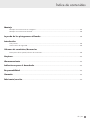
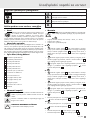
Table of Contents
Assembly
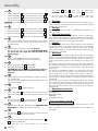
Picture assembly instructions.................................................................................................................... 05
Text assembly instructions......................................................................................................................... 17
Legend of the icons used...................................................................................................................... 17
Introduction
Proper or intended use............................................................................................................................. 17
Safety instructions.................................................................................................................................... 17
Scope of supply/Accessories
Parts description/Scope of supply.............................................................................................................. 17
Cleaning........................................................................................................................................................ 18
Storage.......................................................................................................................................................... 18
Disposal instruction................................................................................................................................. 18
Liability......................................................................................................................................................... 18
Warranty...................................................................................................................................................... 18
Manufacturer/Service............................................................................................................................ 18
16 | EN

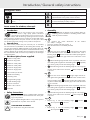
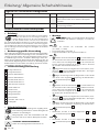
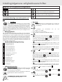
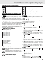
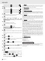
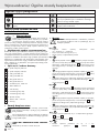
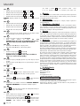
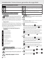
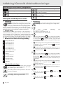
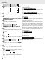
Pictograms used
Fold out the folded page Observe warning and safety instructions!
Read instructions! Do not expose fibreglass fabric or any plastic parts
to open flames or any other source of heat.
Risk of falling down! Do not lean against the
frame.
Products and packaging should be disposed of in
an environmentally friendly manner.
Recycling code for cardboard disposal.
Insect screen for window, telescopic
• Introduction
Congratulations on the purchase of your new product.
You have chosen a high quality product. Familiarise
yourself with the product before using it for the first time.
Please read the following operating instructions and the
safety instructions carefully. Use the product only as described and for
the specified applications. Keep this manual in a safe place. Hand
over all documents when passing on the product to third parties.
• Intended use
The insect screen product may be used only for its intended,
non-commercial use (installation on the existing door frame). Mis-
use may cause hazards. Additional loads on this product due to at-
tached objects or operation beyond the mechanical limitations may
result in damage to the product and are therefore not permitted.
The manufacturer shall not assume any liability for the damages
resulting herefrom.
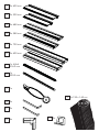
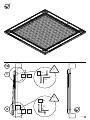
• Part description/Items supplied
2x 620 mm clip profile
2x 520 mm clip profile
2x 680 mm small profile
2x 580 mm small profile
2x 720 mm large profile
2x 620 mm large profile
1x brush 4.8x4, 5160 mm
1x 5200 mm beading
1x beading cutter
2x large bending angle
2x small bending angle
4x corner connectors
1x fabric 120 x 140 cm
1
2
3
4
5
6
7
8
9
10
11
12
13
14 2x handles
• Safety instructions
Please read the instructions carefully before assembly!
Keep the instructions and hand them over when pass-
ing on the product!
Do not expose fibreglass fabric or any plastic parts to
open flames or any other source of heat.
CAUTION! RISK OF INJURY!
Be careful when using the cutter knife.
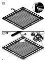
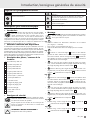
• Assembly
CAUTION! Risk of damage to the product! When as-
sembling, place a blanket or something similar under-
neath to prevent scratches.
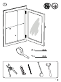
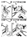
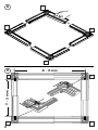
Fig. 1:
• First measure the inside dimensions of the window
(X = width, Y = height)
• Open the window to do this (see Fig. 1)
• Enter the dimensions in the fields provided
Fig. 2:
• a Press one corner connector 12 at right angles to the inside
on the left bottom corner of the outer window frame. Insert a
bending angle 10 from the inside of the window pointing down
with the long side into the gap of the narrow side of the corner
connector.
• 1b Pull the bending angle outside as far as possible, and insert
the bending aid integrated in the beading cutter 9 completely
over the long side piece of the bending angle
• 2b Bend the long side of the bending angle at a 90° angle up
into the recess of the corner connector. The component A
is formed
Fig. 3:
• a Press one corner connector 12 at right angles with the in-
side against the right bottom corner of the outer window frame.
Insert a bending angle 10 from the inside of the window point-
ing down with the long side into the gap of the wide side of the
corner connector.
• 1b Pull the bending angle outside as far as possible, and insert
the bending aid integrated in the beading cutter 9 completely
over the long side piece of the bending angle
• 2b Bend the long side of the bending angle at a 90° angle up
into the recess of the corner connector. The component B
is formed
Fig. 4:
• Repeat Fig. 2 with the bending angle
11
instead
10
The component C is formed
Fig. 5:
• Repeat Fig. 3 with the bending angle
11
instead
10
The component D is formed
Introduction/ General safety instructions
20
PAP
!
!
!
!
EN | 17

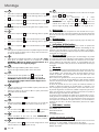
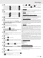
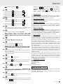
Assembly
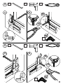
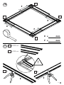
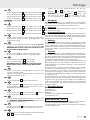
Fig. 6:
• Tap the component
A
with the narrow side in the profile
3
• Tap the component B with the wide side in the profile 5
• Tap the component
C
with the narrow side in the profile
3
• Tap the component D with the wide side in the profile 5
CAUTION!
The bending angle must be pushed into the profile and
not below it!
Fig. 7:
• Tap the component A with the wide side in the profile 6
• Tap the component
B
with the narrow side in the profile
4
• Tap the component C with the wide side in the profile 6
• Tap the component
D
with the narrow side in the profile
4
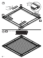
Fig. 8:
• Push the narrow profiles into the wide profiles such that subse-
quently, each of the short and the long bending angles point in
the same direction
Fig. 9:
• Slide the horizontal profiles to the width X-2 mm
• Slide the vertical profiles to the height Y-5 mm CAUTION! Meas-
ure X from the outer edge & Y from the inside of the
bending angle!
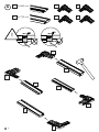
Fig. 10:
• Measure the length
E
of the narrow, vertical profiles
• Measure the length
F
of the narrow, horizontal profiles
Fig. 11:
• Shorten the clip profile 2x
1
to the length E
• Shorten the clip profile 2x
2
to the length F
CAUTION! Shorten the profiles such that each of the cut
edges subsequently lies in the direction of the corner
connector.
Fig. 12:
• Clip the shortened clip profiles
E
along the projection of the nar-
row, vertical profiles
• Clip the shortened clip profiles
F
along the projection of the nar-
row, horizontal profiles
Fig. 13:
• Lay out the fabric
13
straight on the frame
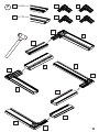
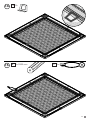
Fig. 14:
• Press in the handles
14
with the short side down opposite on the
sides of the vertical profiles into the inner grooves above the fabric
Fig. 15:
• Press in the beading
8
with the beading cutter
9
around into
the inside grooves over the fabric and handles
Fig. 16:
• Cut off the protruding fabric with a cutter knife.
CAUTION! RISK
OF INJURY!
Be careful when using the cutter knife.
Fig. 17:
• Push the brush
7
via the corner connectors into the outer brush
channel, and shorten each of the projections
Fig. 18:
• First push the insect guard window with the bending angles
A
&
C
up below the blind frame
• Now push the insect guard window with the bend-
ing angles
B
&
D
down over the blind frame
CAUTION!
The long bending angles
10
must point
up & the short ones
11
must point down. Make sure
that the bending angles are hooked in at a 90° angle
• Cleaning
Use only a damp cloth with mild detergent for cleaning. You can
remove dust from the fibreglass fabric with a vacuum cleaner (brush
attachment) or hand broom.
• Storage
Store the product dry and clean in a temperature-controlled room
when not in use.
• Disposal instruction
Don’t forget about environmental protection. There is a public take-
back system for the disposal of packaging materials and old appli-
ances. You can get information about collection points and current
regulations from your city or municipal administration.
• Liability
In the case of non-observance of the instructions and information
given in this manual, in the case of improper use or use outside the
intended purpose, the manufacturer rejects the warranty for damage
to the product. Liability for consequential damage to elements of any
kind or persons is excluded.
• Warranty
The product has been carefully produced according to strict quality
guidelines and conscientiously tested before delivery. In the event of
defects in this product, you have legal rights against the seller of the
product. These statutory rights are not limited by our warranty set out
below.
This product comes with a 3 year warranty from the date of purchase.
The warranty period begins on the date of purchase. Please keep the
original receipt in a safe place. This document is required as proof
of purchase.
If a material or manufacturing defect occurs within three years from
the date of purchase of this product, we will replace the product,
free of charge for you, with a product of our choice. In this case,
the warranty period starts afresh (valid only in Poland and Portugal).
This warranty is void if the product is damaged, improperly used or
maintained.
The warranty covers material or manufacturing defects. This warranty
does not cover product parts that are subject to normal wear and tear
(e.g. weathering) and can therefore be considered wear parts or for
damage to the fabric that has been torn by heavy use (stretching or
sharp objects).
• Manufacturer/Service
bash-tec GmbH
Hoorwaldstr. 42
DE-57299 Burbach
GERMANY
IAN 383938_2107
For all inquiries, please have the receipt and item number (e.g. IAN
12345) available as proof of purchase.
Note: The pictures in this manual are exemplary and may differ from
the product.
18 | EN

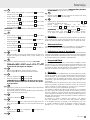
Inhaltsverzeichnis
Montage
Montage als Bildanleitung........................................................................................................................ 05
Montage in Textform................................................................................................................................ 20
Legende der verwendeten Piktogramme..................................................................................... 20
Einleitung
Bestimmungsgemäße Verwendung........................................................................................................... 20
Sicherheitshinweise.................................................................................................................................. 20
Lieferumfang/Zubehör
Teilebeschreibung/Lieferumfang............................................................................................................... 20
Reinigung..................................................................................................................................................... 21
Lagerung...................................................................................................................................................... 21
Entsorgungshinweis................................................................................................................................ 21
Haftung......................................................................................................................................................... 21
Garantie........................................................................................................................................................ 21
Hersteller/Service.................................................................................................................................... 21
DE | 19

20 | DE
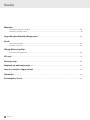
Legende der verwendeten Piktogramme
Einklappseite ausklappen Warn- und Sicherheitshinweise beachten!
Anweisungen lesen! Fiberglasgewebe sowie alle Kunststoffteile nicht
offenem Feuer oder einer anderen Hitzequelle
aussetzen.
Sturzgefahr! Nicht gegen den Rahmen lehnen. Produkte und Verpackungen sollen umweltscho-
nend entsorgt werden.
Recycling-Code zur Entsorgung von Pappe.
Insektenschutz für Fenster teleskopierbar
• Einleitung
Wir beglückwünschen Sie zum Kauf Ihres neuen Produkts.
Sie haben sich damit für ein hochwertiges Produkt ent-
schieden. Machen Sie sich vor der ersten Inbetriebnahme
mit dem Produkt vertraut. Lesen Sie hierzu aufmerksam
die nachfolgende Bedienungsanleitung und die Sicherheitshinweise.
Benutzen Sie das Produkt nur wie beschrieben und für die angegebe-
nen Einsatzbereiche. Bewahren Sie diese Anleitung an einem sicheren
Ort auf. Händigen Sie alle Unterlagen bei Weitergabe des Produktes
an Dritte mit aus.
• Bestimmungsgemäße Verwendung
Das Insektenschutzprodukt darf nur für den bestimmungsgemäßen,
nicht gewerblichen Gebrauch (Montage an den vorhandenen Tür-
rahmen) verwendet werden. Bei missbräuchlicher Nutzung kann es
zu Gefährdungen kommen. Zusätzliche Belastungen dieses Pro-
duktes durch angehängte Gegenstände oder Bedienung über die
mechanischen Begrenzungen hinaus können zur Beschädigung des
Produktes führen und sind daher nicht zulässig. Für hieraus resultie-
rende Schäden haftet der Hersteller nicht.
• Teilebeschreibung/Lieferumfang
2x Clipprofil 620 mm
2x Clipprofil 520 mm
2x Kleines Profil 680 mm
2x Kleines Profil 580 mm
2x Großes Profil 720 mm
2x Großes Profil 620 mm
1x Bürste 4,8x4, 5160 mm
1x Keder 5200 mm
1x Kedermesser
2x Biegewinkel groß
2x Biegewinkel klein
4x Eckverbinder
1x Gewebe 120 x 140 cm
1
2
3
4
5
6
7
8
9
10
11
12
13
14 2x Haltegriffe
• Sicherheitshinweise
Vor der Montage die Anleitung bitte sorgfältig durch-
lesen! Anleitung aufbewahren und bei Weitergabe des
Produktes mit aushändigen!
Fiberglasgewebe sowie alle Kunststoffteile nicht offe-
nem Feuer oder einer anderen Hitzequelle aussetzen.
VORSICHT! VERLETZUNGSGEFAHR!
Gehen Sie vorsichtig mit dem Cuttermesser um.
• Montage
ACHTUNG! Gefahr von Produktschäden! Bei Montage
eine Decke oder Ähnliches unterlegen, um Kratzer zu
verhindern.
Abb. 1:
• Messen Sie zunächst die Innenmaße des Fensters
(X = Breite, Y = Höhe)
• Fenster dazu öffnen (siehe Abb. 1)
• Tragen Sie die Maße in die vorgesehenen Felder ein
Abb. 2:
• a Drücken Sie einen Eckverbinder 12 im rechten Winkel mit
der Innenseite an die linke untere Ecke des äußeren Fensterrah-
mens. Führen Sie einen Biegewinkel 10 von der Innenseite des
Fensters nach unten zeigend mit der langen Seite in die Lücke
der schmalen Seite des Eckverbinders ein.
• 1b Biegewinkel soweit wie möglich nach aussen ziehen, im Ke-
dermesser 9 integrierte Biegehilfe komplett über den langen
Schenkel des Biegewinkels stecken
• 2b Biegen Sie die lange Seite des Biegewinkels im 90° Winkel
nach oben in die vorgesehene Aussparung des Eckverbinders.
Es entsteht Komponente A
Abb. 3:
• a Drücken Sie einen Eckverbinder 12 im rechten Winkel mit
der Innenseite an die rechte untere Ecke des äußeren Fensterrah-
mens. Führen Sie einen Biegewinkel 10 von der Innenseite des
Fensters nach unten zeigend mit der langen Seite in die Lücke
der breiten Seite des Eckverbinders ein.
• 1b Biegewinkel soweit wie möglich nach aussen ziehen, im Ke-
dermesser 9 integrierte Biegehilfe komplett über den langen
Schenkel des Biegewinkels stecken
• 2b Biegen Sie die lange Seite des Biegewinkels im 90° Winkel
nach oben in die vorgesehene Aussparung des Eckverbinders.
Es entsteht Komponente B
Abb. 4:
• Wiederholen Sie Abb. 2 mit dem Biegewinkel
11
statt
10
Es entsteht Komponente C
Abb. 5:
• Wiederholen Sie Abb. 3 mit dem Biegewinkel
11
statt
10
Es entsteht Komponente D
Einleitung/ Allgemeine Sicherheitshinweise
!
!

Montage
Abb. 6:
• Klopfen Sie Komponente
A
mit der schmalen Seite in Profil
3
• Klopfen Sie Komponente B mit der breiten Seite in Profil 5
• Klopfen Sie Komponente
C
mit der schmalen Seite in Profil
3
• Klopfen Sie Komponente D mit der breiten Seite in Profil 5
ACHTUNG!
Der Biegewinkel muss in das Profil geschoben werden,
nicht darunter!
Abb. 7:
• Klopfen Sie Komponente A mit der breiten Seite in Profil 6
• Klopfen Sie Komponente
B
mit der schmalen Seite in Profil
4
• Klopfen Sie Komponente C mit der breiten Seite in Profil 6
• Klopfen Sie Komponente
D
mit der schmalen Seite in Profil
4
Abb. 8:
• Schieben Sie die schmalen Profile in die breiten Profile, sodass
hinterher jeweils die kurzen und die langen Biegewinkel in die
gleiche Richtung zeigen
Abb. 9:
• Schieben Sie die waagerechten Profile auf die Breite X-2 mm
• Schieben Sie die senkrechten Profile auf die Höhe Y-5 mm
ACHTUNG! Messen Sie X von der Aussenkannte & Y von
der Innenseite der Biegewinkel!
Abb. 10:
• Messen Sie die Länge
E
der schmalen, senkrechten Profile
• Messen Sie die Länge
F
der schmalen, waagerechten Profile
Abb. 11:
• Kürzen Sie 2x das Clipprofil
1
auf die Länge E
• Kürzen Sie 2x das Clipprofil
2
auf die Länge F
ACHTUNG! Kürzen Sie die Profile so, das die Schnitt-
kannte später jeweils in Richtung des Eckverbinders
liegt!
Abb. 12:
• Clipsen Sie die gekürzten Clipprofile
E
auf den Überstand der
schmalen, senkrechten Profile
• Clipsen Sie die gekürzten Clipprofile
F
auf den Überstand der
schmalen, waagerechten Profile
Abb. 13:
• Legen Sie das Gewebe
13
gerade auf dem Ramen aus
Abb. 14:
• Drücken Sie die Griffe
14
mit der kurzen Seite nach unten gegen-
überliegend auf den Seiten der senkrechten Profile in die innen-
liegende Rillung über dem Gewebe ein
Abb. 15:
• Drücken Sie den Keder
8
mit dem Kedermesser
9
rundum in
die innenliegende Rillung über Gewebe und Griffen ein
Abb. 16:
• Schneiden Sie das überstehende Gewebe mit einem Cuttermesser
ab.
VORSICHT! VERLETZUNGSGEFAHR!
Gehen Sie vor-
sichtig mit dem Cuttermesser um.
Abb. 17:
• Schieben Sie die Bürste
7
über die Eckverbinder in den außen-
liegenden Bürstenkanal ein, kürzen Sie jeweils den Überstand
Abb. 18:
• Schieben Sie zuerst das Insektenschutzfenster mit den Biegewinkeln
A
&
C
nach oben unter den Blendrahmen
• Schieben Sie nun das Insektenschutzfenster mit den Bie-
gewinkeln
B
&
D
nach unten über den Blendrahmen
ACHTUNG!
Die langen Biegewinkel
10
müssen nach
oben zeigen & die kurzen
11
nach unten. Stellen Sie sicher,
dass die Biegewinkel im 90° Winkel eingehangen werden.
• Reinigung
Verwenden Sie zur Reinigung nur ein feuchtes Tuch mit mildem Reini-
gungsmittel. Das Fiberglasgewebe können Sie mit einem Staubsau-
ger (Bürstenaufsatz) oder Handbesen von Staub befreien.
• Lagerung
Lagern Sie das Produkt bei Nichtgebrauch trocken und sauber in
einem temperierten Raum.
• Entsorgungshinweis
Denken Sie an den Umweltschutz. Zur Entsorgung von Verpackungs-
materialien und Altgeräten gibt es ein öffentliches Rücknahmesystem.
Auskünfte über Sammelstellen und aktuelle Bestimmungen erhalten
Sie bei Ihrer Stadt- oder Gemeindeverwaltung.
• Haftung
Bei Nichtbeachtung der in dieser Anleitung angegebenen Hinweise
und Informationen, bei nicht bestimmungsgemäßem Gebrauch oder
Einsatz außerhalb des vorgesehenen Verwendungszwecks lehnt der
Hersteller die Gewährleistung für Schaden am Produkt ab. Die Haf-
tung für Folgeschäden an Elementen aller Art oder Personen ist aus-
geschlossen.
• Garantie
Das Produkt wurde nach strengen Qualitätsrichtlinien sorgfältig pro-
duziert und vor Anlieferung gewissenhaft geprüft. Im Falle von Män-
geln dieses Produkts stehen Ihnen gegen den Verkäufer des Produkts
gesetzliche Rechte zu. Diese gesetzlichen Rechte werden durch unsere
im Folgenden dargestellte Garantie nicht eingeschränkt.
Sie erhalten auf dieses Produkt 3 Jahre Garantie ab Kaufdatum. Die
Garantiefrist beginnt mit dem Kaufdatum. Bitte bewahren Sie den
Original-Kassenbon gut auf. Diese Unterlage wird als Nachweis für
den Kauf benötigt.
Tritt innerhalb von drei Jahren ab dem Kaufdatum dieses Produkts
ein Material- oder Fabrikationsfehler auf, wird das Produkt von uns -
nach unserer Wahl - für Sie kostenlos ersetzt. In diesem Fall beginnt
die Garantiezeit erneut (gilt nur in Polen und Portugal). Diese Garan-
tie verfällt, wenn das Produkt beschädigt, nicht sachgemäß benutzt
oder gewartet wurde.
Die Garantieleistung gilt für Material- oder Fabrikationsfehler. Diese
Garantie erstreckt sich nicht auf Produktteile, die normaler Abnutzung
ausgesetzt sind (z. B. Verwitterung) und daher als Verschleißteile an-
gesehen werden können oder für Beschädigungen am Gewebe, das
durch starke Beanspruchung (Dehnung oder scharfe Gegenstände)
eingerissen wurde.
• Hersteller/Service
bash-tec GmbH
Hoorwaldstr. 42
DE-57299 Burbach
GERMANY
kostenlose Service-Hotline: +49-8000009202
IAN 383938_2107
Bitte halten Sie für alle Anfragen den Kassenbon und die Artikelnum-
mer (z. B. IAN 12345) als Nachweis für den Kauf bereit.
Hinweis: Die Bilder in dieser Anleitung sind exemplarisch und können
vom Produkt abweichen.
DE | 21
La page charge ...
La page charge ...
La page charge ...
La page charge ...
La page charge ...
La page charge ...
La page charge ...
La page charge ...
La page charge ...
La page charge ...
La page charge ...
La page charge ...
La page charge ...
La page charge ...
La page charge ...
La page charge ...
La page charge ...
La page charge ...
La page charge ...
La page charge ...
La page charge ...
La page charge ...
La page charge ...
La page charge ...
La page charge ...
La page charge ...
-
 1
1
-
 2
2
-
 3
3
-
 4
4
-
 5
5
-
 6
6
-
 7
7
-
 8
8
-
 9
9
-
 10
10
-
 11
11
-
 12
12
-
 13
13
-
 14
14
-
 15
15
-
 16
16
-
 17
17
-
 18
18
-
 19
19
-
 20
20
-
 21
21
-
 22
22
-
 23
23
-
 24
24
-
 25
25
-
 26
26
-
 27
27
-
 28
28
-
 29
29
-
 30
30
-
 31
31
-
 32
32
-
 33
33
-
 34
34
-
 35
35
-
 36
36
-
 37
37
-
 38
38
-
 39
39
-
 40
40
-
 41
41
-
 42
42
-
 43
43
-
 44
44
-
 45
45
-
 46
46


LIVARNO 383938 Le manuel du propriétaire
- Taper
- Le manuel du propriétaire
dans d''autres langues
- español: LIVARNO 383938 El manual del propietario
- Deutsch: LIVARNO 383938 Bedienungsanleitung
- Nederlands: LIVARNO 383938 de handleiding
- slovenčina: LIVARNO 383938 Návod na obsluhu
- dansk: LIVARNO 383938 Brugervejledning
- polski: LIVARNO 383938 Instrukcja obsługi
Documents connexes
Autres documents
-
Hitachi VB 13Y Le manuel du propriétaire
-
Rothenberger Electric bender ROBEND 4000 set Manuel utilisateur
-
Celexon Cadre mural haut contraste CLR Home Cinema UST 120", 265 x 149 cm Le manuel du propriétaire
-
DURKOPP ADLER 961-23 Manuel utilisateur
-
Sima STAR 16 Manuel utilisateur
-
 Kromschroder ES Mode d'emploi
-
Kettler ERGOCOACH LS Training And Operating Instructions
-
Powermatic PM1500 Operating Instructions Manual
-
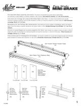 Malco Pan Style Mini-Brake Mode d'emploi

