
Your ventilation system should be installed in conformance with the appropriate provincial requirements or, in the absence of
such requirements, with the current edition of the National Building Code, and / or ASHRAE’s “Good Engineering Practices”.
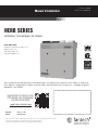
HERO SERIES
Fresh Air Appliance (HRV)
Installation and Operation Manual
Item #: 428486
Rev Date: 2020-01-23
PARTS IN THE BOX
Heat Recovery Ventilator, 1 pc
Hanging Bracket, 1 pc
Drain Hose Kit, 1 pc
Operation and Installation Manual, 1 pc
Fantech reserves the right to modify, at any time and without notice, any or all of its products’ features, designs,
components and specifications to maintain their technological leadership position.
Please visit our website www.fantech.net for more detailed technical information.
United States 800.747.1762
Canada 800.565.3548
registration.fantech.app
REGISTER THIS PRODUCT TO
BE REMINDED OF SUGGESTED
PRODUCT CARE SCHEDULE

2
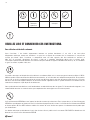
Note Warning/
Important
note
Information Technical
information
Practical tip
PLEASE READ AND SAVE THESE INSTRUCTIONS
For residential use only
Before installation careful consideration must be given to how this system will operate if connected to any other piece of mechanical
equipment, i.e., a forced air furnace or air handler operating at a higher static pressure. After installation, the compatibility of the two pieces of
equipment must be conrmed by measuring the airow of the Heat Recovery Ventilator using the balancing procedure found in this manual.
It is always important to assess how the operation of any HRV may interact with vented combustion equipment (i.e., Gas Furnaces, Oil
Furnaces, Wood Stoves, etc.)
Products are designed and manufactured to provide reliable performance, but they are not guaranteed to be 100% free of defects.
Even reliable products will experience occasional failures, and this possibility should be recognized by the user. If these products are
used in a life support ventilation system where failure could result in loss or injury, the user should provide adequate back-up ventilation,
supplementary natural ventilation or failure alarm system, or acknowledge willingness to accept the risk of such loss or injury.
Your ventilation system should be installed in accordance with the local building code that is in effect, in absence of such requirements, it
is recommenced to check with local authorities having jurisdiction in your area prior to installing this product.
The MERV8 supply lter provided with the unit is intended for areas that it is required. In most cases the MERV8 supply lter is not
required and it becomes optional at the home owner’s discretion. Installing the MERV8 supply lter or other MERV lter options will affect
the maximum airow of the unit, please refer to product documentation for more information.
Technical data was obtained from published results of test relating to CSA C439 Standards. This data was optained without the use of
the MERV8 supply lter.

3
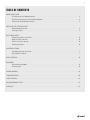
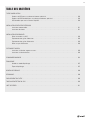
TABLE OF CONTENTS
INSTALLATION TYPES
HRV ducting for fully Dedicated System .................................................... 4
HRV/Furnace ducting for Partially Dedicated System.............................................4
HRV/furnace for Simplified Installation ...................................................... 4
INSTALLING THE OUTDOOR VENTS
Recommended Installation .............................................................. 5
Installing the vents ................................................................... 5
DUCT INSTALLATION
Connecting the Ducts to the HRV ......................................................... 6
Supply Air Grilles Location .............................................................. 6
Exhaust Air Grille’s Location ............................................................. 6
Connecting the Drain ...................................................................6
MOUNTING OPTIONS
Wall Mouting Bracket Installation ......................................................... 7
Chain Mount Installation................................................................ 7
WALL CONTROLS ............................................................................8
BALANCING
Entering Balancing Mode ............................................................... 9
Balancing steps ..................................................................... 9
WIRING DIAGRAM ......................................................................... 10
TROUBLESHOOTING .........................................................................13
FILTER LOCATION ...........................................................................14
HRV MAINTENANCE CHART ...................................................................14
PARTS LIST ...............................................................................15

4
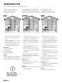
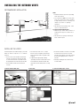
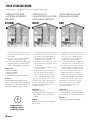
INSTALLATION TYPES
Example only – duct configuration may differ depending on the model.
1. Stale air is drawn from areas requiring
local exhaust (bathroom, kitchen, laundry
room).
2. Fresh air is distributed to habitable rooms
(bedrooms, living room)
3. The HRV’s airflow must be balanced after
installation using the procedure found in
the section “AIRFLOW BALANCING.”
Suggested for:
• Hydronic baseboard
• In oor heating
• Electric baseboard
• Mini split heat pump
Benets:
Provides the best fresh air distribution in
the house; lowest operation cost since the
furnace/air handler unit is not needed.
1. The furnace blower is set to run
continuously or interconnected with HRV
for proper fresh air distribution. See
furnace electrical connection on page 12.
2. Stale air is drawn from areas requiring
local exhaust (bathroom, kitchen, laundry
room).
3. Fresh air is supplied to the return air
plenum of the furnace.
4. Due to the difference in pressure, HRV's
airflow must be balanced on site using the
procedure found in the section “AIRFLOW
BALANCING.”
* In the case of a multi-zone system, please
contact Fantech customer service prior to
installing any installation type requiring the use
of the furnace interlock
Suggested for:
• Central furnace
• When ducting fresh air to living area is
not possible or practical
Benets:
Conditions the fresh air prior to distributing
it throughout the house
1. The furnace blower is set to run
continuously or interconnected with HRV
for proper fresh air distribution. See
furnace electrical connection on page 12.
2. A minimum separation of 1m (39’’) is
recommended between the two direct
connections.
3. The HRV’s exhaust air connection should be
upstream of the HRV’s supply air
connection to prevent exhausting any fresh
air.
4. Due to the difference in pressure, HRV's
airflow must be balanced on site using the
procedure found in the section “AIRFLOW
BALANCING.”
* In the case of a multi-zone system, please
contact Fantech customer service prior to
installing any installation type requiring the use
of the furnace interlock"
Suggested for:
• When bathroom and kitchen already have
local exhaust system
• May be suitable for retrofitting
Benets:
Least expensive installation type
HRV DUCTING FOR FULLY
DEDICATED SYSTEM
HRV/FURNACE DUCTING FOR
PARTIALLY DEDICATED SYSTEM
HRV/FURNACE FOR
SIMPLIFIED INSTALLATION
BEST BETTER GOOD
Make sure the HRV is
capable of meeting the
required airow rate.

5
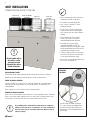
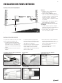
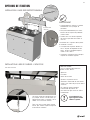
INSTALLING THE OUTDOOR VENTS
RECOMMENDED INSTALLATION
INSTALLING THE VENTS
18"
(460mm)
36"
(1m)
3'
(900mm)
min.
36"
(1m)
Intake
• Should be located upstream of prevailing
winds from exhaust
• At a minimum of 900 mm (3') away from
dryer vents and furnace exhaust (medium
or high efficiency furnaces), driveways, oil
fill pipes, gas meters, or garbage
containers.
• Do not locate in the garage, attic, crawl
space, or underneath deck.
Locating the Exhaust Weatherhood
• Not near a gas meter, electric meter or a
walkway where fog or ice could create a
hazard
• Do not locate in a garage, workshop or
other unheated space
A well designed and installed ducting system will
allow the HRV to operate at its maximum
efficiency.
• The inner liner of the flexible insulated duct
must be secured to the sleeve of the hood
(as close to the outside as possible) and to
the appropriate duct connection on the HRV.
• The insulation should remain full and not
crushed.
1. Cut hole between wall studs
3. Secure vent with proper screws
4. Seal using outdoor rated caulking 5. Attach insulated duct from inside and tape
2. Insert vent
• The outer liner, which acts as a vapor
barrier, must be completely sealed to the
outer wall and the HRV using tape and/or
caulking.
• A good bead of high quality caulking
(preferably acoustical sealant) will seal the
inner flexible duct to both the HRV duct
connection and the hood prior to securing
them.
• To minimize airflow restriction, the flexible
insulated duct that connects the two
outside weatherhoods to the HRV should
be stretched tightly and be as short as
possible.
• Twisting or folding the duct will severely
restrict airflow.

6
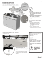
DUCT INSTALLATION
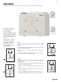
CONNECTING THE DUCTS TO THE HRV
STALE AIR
FROM HOME
EXHAUST TO
OUTDOOR HOOD
FRESH AIR
TO HOME
FRESH OUTDOOR
AIR INTAKE
• Ducts should be kept short and have as
few bends or elbows as possible.
• 45º elbows are preferable to 90º.
• Use “Y“ ducts instead of “T” ducts
whenever possible.
• All duct joints must be fastened with
screws or duct sealant and wrapped
with aluminum foil duct tape to prevent
leakage.
• Galvanized ducting from the HRV
to the living areas in the house is
recommended whenever possible.
• To reduce noise a short length
(approximately 300mm, 12’’) of
nonmetallic exible insulated duct should
be connected between the HRV and the
supply/exhaust ductwork system.
• The main supply and return line to/from
the HRV must have the same diameter
as the duct connection or larger.
• Branch lines to the individual rooms may
be as small as 100mm (4’’).
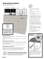
INSTALLING DUCT TO HRV
Flexible Duct: Slide exible ducting onto duct connection and afx with cable tie.
Solid Ducting: slide duct over duct connection, screw in place and seal.
SUPPLY AIR GRILLES LOCATION
Without a forced air furnace: fresh air should be supplied to all habitable rooms
from high wall or ceiling locations. Grilles that diffuse the air comfortably are
recommended.
With a forced air furnace: Connect to the furnace ductwork.
EXHAUST AIR GRILLE’S LOCATION
Draw stale air from the points where the worst air quality problems occur: bathroom,
kitchen, and laundry room. Additional return air ducts from strategic locations may
be installed. The furnace return duct may also be used to exhaust from.
As per building codes and installation requirements for combustion
appliances: Air return ducts, or openings for air return, should not be
placed in enclosed spaces containing combustion appliances that are
subject to spillage.
Install the drain hose making a
"P" trap, secure the condensate
line drain to HRV by sliding into
connection. Fill the condensate line
with water.
INSTALLING
THE DRAIN
Do not handle unit by
the collars / collar
openings to avoid
damaging the collars
& foam insulation.

7
MOUNTING OPTIONS
LOCATION
• Must be located in a conditioned space
where it will be possible to conveniently
service the unit.
• Typically located close to the outside wall
where the hoods will be mounted.
• A utility room when basement is not
possible.
Attic installation must meet the following
conditions:
• Attic temperature must be above
freezing conditions at all times and
for best performance should be
12°C (54 °F).
• The attic is easily accessible for
equipment maintenance and inspection.
WALL MOUTING BRACKET INSTALLATION
CHAIN MOUNT INSTALLATION - OPTIONAL
* Hanging kit not included.
When wall mount bracket is not
convenient. Use a chain kit (which includes
hanging chains, 10-24 screws, spring, and
hooks)
Install a spring on each chain as shown
to support the unit's weight and absorb
vibrations.
Safety screws
(included)
16” (406mm)
DO NOT
Connecting appliances to the HRV is not
recommended. These include:
• Clothes dryer
• Range top
• Stovetop fan
• Central vacuum system
• Bathroom exhaust fans unless they are
specically designed for this purpose
• These appliances may cause lint, dust or
grease to collect in the HRV, damaging
the unit.
Connecting any of these
types of appliances to
the HRV will void your
warranty.

8
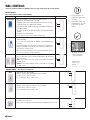
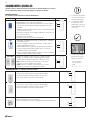
WALL CONTROLS
AUXILIARY CONTROL – These controls can be paired
RTS2*
• 20- minute timer with LED light
• Boosts system to high speed with the touch of a button
• Up to 5 can be used in one system
• Use in bathroom, kitchen, laundry room
RTS5 • 20/40/60 minute timer with LED light
• Boosts system to high speed with the touch of a button
• Up to 5 can be used in one system
• Use in bathroom, kitchen, laundry room
MDEH1 • Rotary dial Dehumidistat
• Multiple units can be used
• We recommend setting the relative humidity above 80% during the summer
* Please see instruction manuals for individual controls for proper wiring and set up of control systems.
CENTRAL CONTROLS
These control options can only be used individually.
CONTROLS FEATURES CONNECT TO
ECO-Touch® • Our most complete, yet easy-to-use control system
• Sleek design with backlight touchscreen LCD
• ECO mode selects the best operating mode and speed for the season,
minimizing energy use associated with ventilation
• Set preferred indoor relative humidity range and ventilation mode for day
and night conditions
• No battery to replace, all programmed settings are retained during power
outages
• Maintenance reminder indicator
• Error code messages reduce troubleshooting time
EDF7
• MODE button provides 3 modes of operations: Ventilation , Recircula-
tion and Standby
• User selected fan speed: Reduced, Medium, Normal and 20 minutes
per hour
• AUTO setting allows the homeowner to deactivate the dehumidistat
• When the humidity exceeds the desired setpoint, the ventilation sys-
tem operates at normal speed
• Once the desired humidity level is achieved, your ventilation system
resumes to its previous mode of operation.
EDF1 / EDF1R • Press button once for continuous Reduced speed
• Press button twice and the unit will cycle 20 minutes ON/ 40 minutes
OFF and repeat
• EDF1 – Press button a third time and the system will run continuously
on HIGH speed
• EDF1R –Press button a third time and the system will run recirculation
on HIGH speed.
1. Ensure that unit is not
plugged when connecting
the control
2. Recirculation mode is only
available with the “R” sufx
at the end of the model
number.
The wiring connectors
can be removed for
easier connection.
*Maintain polarity
between control
and HRV
(+ → + ; - → -)
W
W
W
W
W
W
+T
-T
D
D
+T
-T

9
BALANCING
Balancing must be completed using the Fantech ECO-Touch
®
Programmable Touch Screen Wall Control
ENTERING BALANCING
MODE
In the options menu during
the initial 5 second countdown
sequence, long press on "ECO"
area for 5 seconds to enter
basic balancing mode.
The supply and exhaust fans are
adjusted on high speed only and
the offsets are proportionally
applied to the medium and low
speed automatically.
AUTO MANUAL
OPTIONS
AUTO MANUAL
OPTIONS
NEXT
Supply
manometer
High
High
Low
Low
Exhaust
manometer
STAGE 1
(ADJUST LEVEL OF EXHAUST FAN IN HIGH SPEED):
• In this step, balance exhaust fan and measure airow on the
exhaust air side
• Pressing on "up" or "down" will adjust the fan speed in increments
of 1%.
• Once the desired exhaust airow is reached, press on "next" and
move on to the next stage.
STAGE 2
(BALANCE SUPPLY FAN ONLY IN HIGH SPEED):
• In this step, balance supply fan and measure airow on the supply
air side
• Pressing on "up" or "down" will adjust the fan speed in increments
of 1%.
• Once happy with the outcome, press on "next" to complete
balancing
• The supply and exhaust offset values will be proportionally applied
to low and medium speed as well.
AUTO MANUAL
OPTIONS
NEXT
0 %
ADJUST
AUTO MANUAL
OPTIONS
NEXT
0 %
BALANCE

10
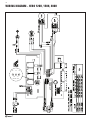
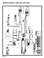
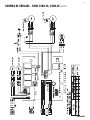
WIRING DIAGRAM - HERO 120H, 150H, 200H
LOW SPEEDS
90V75V
J4J5J6

11
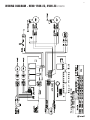
WIRING DIAGRAM - HERO 150H-EC, 250H-EC (CONT'D)

12
W
R
G
C
Y
W
R G
Y
Standard Furnace Interlock Wiring
THERMOSTAT
TERMINALS
FURNACE
24-VOLT
TERMINAL BLOCK
FOUR
WIRE
TWO WIRE
heating only
TWO
WIRE
COOLING SYSTEM
W
R
G
C
Y
W
R G
Y
Alternate Furnace Interlock Wiring
THERMOSTAT
TERMINALS
FURNACE
24-VOLT
TERMINAL BLOCK
FOUR
WIRE
TWO WIRE
heating only
TWO
WIRE
COOLING SYSTEM
WIRE JOINT
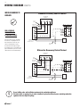
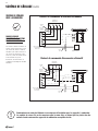
WIRING DIAGRAM (CONT'D)
WIRING DIAGRAM TO
FURNACE
FOR A FURNACE
CONNECTION TO
A COOLING SYSTEM:
On some newer furnaces and older
thermostats, energizing the R and
G terminal at the furnace has the
effect of energizing the Y at the
thermostat and thereby turning on
the cooling system. If you identify this
type of thermostat, you must use the
“Alternate Furnace Interlock Wiring.”
Standard Accessory Control Contact
Alternative Accessory Control Contact
As per building codes and installation requirements for combustion appliances:
Air return ducts, or openings for air return, should not be placed in enclosed spaces containing combustion
appliances that are subject to spillage.

13
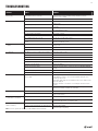
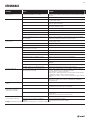
TROUBLESHOOTING
Problem Causes Solutions
Air is too dry Dehumidistat control is set too low Increase the desired level of humidity. Change ventilation mode from
continuous mode to standby.
HRV out of balance Have contractor balance HRV airows
Air is too humid Dehumidistat control is set too high Reduce the desired level of humidity. Combine this with the use of continuous
exchange mode.
Sudden change in temperature Wait until outside temperature stabilizes (winter). Heating will also improve
the situation.
Storing too much wood for heating Store a majority of your wood outside. Even dried, a cord of wood contains
more than 20 gallons of water.
Dryer vent exhaust is inside home Make sure the dryer vent is exhausting outside.
Poor air circulation near windows Open curtains or blinds.
HRV out of balance Have contractor balance HRV airows
Well sealed basement door is closed Open the door or install a grill on the door.
Failed damper system may be stuck in recirculation
mode
Check defrost damper. If damper is always blocking incoming fresh air, have
contractor verify damper system.
Persistent condensation
on window
Improper adjustment of dehumidistat control Reduce the desired level of humidity. Combine this step with use of continuous
exchange mode.
HRV out of balance Have contractor balance HRV
Poor air circulation near windows Open curtains or blinds.
Poor Air Flows 1/4" (6 mm) mesh on the outside hoods is plugged Clean exterior hoods or vents
Filters plugged Remove and clean lter
Core obstructed Remove and clean core
Indoor grilles closed or blocked Check and open grilles
Inadequate power supply at site Have electrician check supply voltage
Ductwork is restricting airow Check duct installation
Improper speed control setting Increase the speed of the HRV (i.e. change unit control from REDUCED to NORMAL
speed)
HRV airow improperly balanced Have contractor balance HRV airows
Ducting has fallen down or been disconnected from HRV Have contractor reconnect ducting
Supply air feels cold Poor location of supply grilles, the airow may irritate
the occupant
Locate the grilles high on the walls or under the baseboards, install ceiling
mounted diffuser or grilles so as not to directly spill the supply air on the
occupant (eg. Over a sofa)
Turn down the HRV supply speed. A small duct heater (1 kw) could be used to
temper the supply air
Placement of furniture or closed doors is restricting the movement of air in
the home
Outdoor temperature extremely cold If supply air is ducted into furnace return, the furnace fan may need to run
continuously to distribute ventilation air comfortably
HRV and/or Ducts frosting up HRV air ows are improperly balanced Have HVAC contractor balance the HRV airows
Malfunction of the HRV defrost system Note: minimal frost build-up is expected on the core before unit initiates
defrost cycle functions
Condensation or Ice Build Up in
Insulated Duct to the Outside
Incomplete vapor barrier around insulated duct Tape and seal all joints
A hole or tear in outer duct covering Tape any holes or tears made in the outer duct covering
Ensure that the vapor barrier is completely sealed.
LED is ashing Everything is in good operations
LED is not ashing No Power is being transmitted to the Control Board Make sure unit is plugged.
Transformer may need replacing.
Note: It is best to get the unit checked by a certied HVAC Contractor/Technician.

14
Limited Warranty
• The Heat recovery core has a
Limited Lifetime Warranty.
• The warranty is limited to 5 years on
parts and 7 years on fans from the
date of purchase, including parts
replaced during this time period. If
there is no proof of purchase
available, the date associated with
the serial number will be used for
the beginning of the warranty period.
• The fans found in all Fantech HRVs
require no lubrication, and are
factory balanced to prevent vibration
and promote silent operation.
• The limited warranty covers
normal use. It does not apply to
any defects, malfunctions or
failures as a result of improper
installation, abuse, mishandling,
misapplication, fortuitous
occurrence or any other
circumstances outside Fantech’s
control.
• Inappropriate installation or
maintenance may result in the
cancellation of the warranty.
• Any unauthorized work will result in
the cancellation of the warranty.
* This warranty is the exclusive and only warranty
in effect relative to the ventilation system and all
other warranties either expressed or implied are
invalid.
HRV MAINTENANCE CHART
FILTER LOCATION
Maintenance Required Recommended Frequency Date Maintenance Performed
Check and Clean
Electrostatic Filters
Every 3 months or if
dirty
Check and replace
Merv 8 Filter
Every 3 months or if
dirty
Check Heat Recovery
Core
Every 6 months
Check Drain Pan and
Lines
Every 3 months
Vacuum the Inside of the
Unit
Annually
Clean and Un-block
Outside
Hoods
Annually
Clean and Inspect Duct
Work
Annually
General Servicing by a
Qualied Contractor
Annually
* Schedule may be altered to meet your own needs. More frequent servicing may be required depending on the
severity of your home's indoor and outdoor environments.
Contractor Telephone Number Date Serviced
Electrostatic
Filters
Merv 8 Filter

15
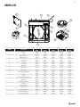
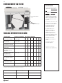
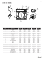
PARTS LIST
1
2
3
7
9
10
4
11
12
5
6
8
13
BOM # Description
HERO 120H
(99400)
HERO 150H
(99401)
HERO 200H
(99402)
HERO 150H-EC
(463253)
HERO 250H-EC
(463254)
1 MOTOR 428469 428515 428516 428517 428518
2 CELL 414708 414709 414710 414709 414710
3 MERV1 (pack of 2) 428519 428520 428521 428520 428521
4 MERV8 (pack of 2) 428525 428526 428527 428526 428527
5 CAPACITOR 410012 410012 410012 N/A N/A
6 PC board 428252 428252 428252 428252 428252
7 Door Switch 410867 410867 410867 410867 410867
8 Transformer 411963 411963 411963 411963 411963
9 Speed switch 410213 410213 410213 410213 410213
10 Metal Collar 428674 428675 428675 428675 428675
11 Plastic collar with Damper 414746 414747 414747 414747 414747
12 Door 428541 428542 428542 428542 428542
13 damper 428543 428543 428543 428543 428543
Fuse, 8 AMP, 250 VAC 3AB 3AG 414736 414736 414736 414736 414736
Temp probe 40286 40286 40286 40286 40286
Damper Door, Defrost 428544 428544 428544 428544 428544
Kit,chain 404261 404261 404261 404261 404261
Kit, Wall Bracket 428545 428546 428546 428546 428546
Wiring Diagram 428481 428481 428481 428482 428482
Installation Manual 428486 428486 428486 428486 428486
Filter MERV13 (pack of 2) NA 428548 428549 428548 428549
Filter HEPA (pack of 2) NA 428551 428552 428551 428552

16
NOTES

Votre système de ventilation doit être installé conformément aux exigences de la province où vous habitez ou, à défaut de
telles exigences, conformément à l’édition actuelle du Code national du bâtiment du Canada ou aux « méthodes d’ingénierie
appropriées » de l’ASHRAE.
HERO SERIES
Ventilateur récupérateur de chaleur
Manuel d'installation
No. d'article #: 428486
Date de révision: 2020-01-23
PIÈCES DANS LA BOÎTE
Ventilateur récupérateur de chaleur, 1 pc
Support muraux, 1 pc
Tuyau d’évacuation, 1 pc
Manuel d'installation, 1 pc
Fantech reserves the right to modify, at any time and without notice, any or all of its products’ features, designs,
components and specifications to maintain their technological leadership position.
Please visit our website www.fantech.net for more detailed technical information.
États Unis 800.747.1762
Canada 800.565.3548
registration.fantech.app
ENREGISTREZ CE PRODUIT POUR
ÊTRE RAPPELÉ DU PROGRAMME
D'ENTRETIEN SUGGÉRÉ

18
Remarque Avertissement/
Remarque
importante
Information Information
technique
Conseil pratique
VEUILLEZ LIRE ET CONSERVER CES INSTRUCTIONS.
Pour utilisation résidentielle seulement.
Avant l’installation, il faut étudier soigneusement comment ce système fonctionnera s’il est relié à une autre pièce
d’équipement mécanique, comme une chaudière à air pulsé ou un appareil de traitement de l’air fonctionnant à une pression
statique plus élevée. Après l’installation, la compatibilité entre ces deux appareils doit être conrmée en mesurant le
débit d’air du ventilateur récupérateur de chaleur à l’aide de la procédure d’équilibrage décrite dans le présent guide.
Il est toujours important d’évaluer comment l’utilisation d’un VRC peut inuencer les appareils de combustion ventilés (p. ex., les chaudières
au gaz et au mazout, les poêles à bois, etc.).
Les produits sont conçus et fabriqués dans le but de fournir un rendement able, mais ils ne sont pas garantis contre les défauts à 100%.
Même les produits ables connaîtront des défaillances occasionnelles, et l’utilisateur doit tenir compte de cette possibilité. Si ces produits
sont utilisés au sein d’un système de ventilation de survie où une défaillance pourrait entraîner des pertes ou des blessures, l’utilisateur
doit fournir une ventilation d’appoint adéquate, une ventilation naturelle supplémentaire ou un système d’alarme en cas de défaillance, ou
reconnaître et accepter le risque de pertes ou de blessures.
Votre système de ventilation doit être installé conformément au code du bâtiment local en vigueur. En l’absence de telles exigences, il est
recommandé de consulter les autorités locales ayant compétence dans votre région avant d’installer ce produit.
Le ltre d’alimentation MERV8 fourni avec l’appareil est destiné aux zones qui le nécessitent. Dans la plupart des cas, le ltre d’alimentation
MERV8 n’est pas obligatoire et il devient facultatif à la discrétion du propriétaire de la maison. L'installation du ltre d'alimentation MERV8
ou d'autres options de ltre MERV affectera le débit d'air maximal de l'unité. Veuillez vous reporter à la documentation du produit pour
plus d'informations.
Les données techniques ont été obtenues à partir des résultats d’essais publiés relatifs aux normes CSA C439. Ces données ont été
obtenues sans utiliser le ltre d'alimentation MERV8.

19
TABLE DES MATIÈRES
TYPES D’INSTALLATION
Conduits de VRC pour un système entièrement spécialisé ...................................... 20
Conduits de VRC/chaudière pour un système partiellement spécialisé .............................. 20
VRC/chaudière pour une installation simplifiée ............................................... 20
INSTALLATION DES ÉVENTS EXTÉRIEURS
Installation recommandée.............................................................. 21
Installation des évents ............................................................... 21
INSTALLATION DES CONDUITS
Relier les conduits au VRC ............................................................. 22
Emplacement des grilles d’admission...................................................... 22
Emplacement des grilles d’évacuation ..................................................... 22
Relier le tuyau d’évacuation............................................................. 22
OPTIONS DE FIXATION
Installation à l’aide des supports muraux ................................................... 23
Installation à l’aide de chaînes........................................................... 23
COMMANDES MURALES ..................................................................... 24
ÉQUILIBRAGE
Accéder au mode d’équilibrage .......................................................... 25
Étapes d’équilibrage.................................................................. 25
SCHÉMA DE CÂBLAGE ...................................................................... 26
DÉPANNAGE.............................................................................. 29
EMPLACEMENT DU FILTRE ................................................................... 30
TABLEAU D’ENTRETIEN DU VRC.................................................................30
LISTE DE PIÈCES............................................................................31

20
TYPES D’INSTALLATION
Exemple seulement: la configuration des conduits peut différer selon le modèle.
1. L’air vicié est évacué des pièces nécessitant
une évacuation locale (salle de bains, cuisine,
salle de lavage).
2. L’air frais est distribué aux pièces habitables
(chambres à coucher, salle de séjour).
3. Le débit d’air du VRC doit être équilibré après
l’installation à l’aide de la procédure décrite à
la section «ÉQUILIBRAGE DU DÉBIT D’AIR».
Suggéré pour:
• Plinthes hydroniques
• Planchers chauffants
• Plinthes électriques
• Thermopompes à deux blocs miniatures
Avantages:
Assure la meilleure distribution d’air frais
dans la maison et offre le coût d’utilisation le
plus faible, car un appareil de traitement de
l’air ou une chaudière ne sont pas requis.
1. La soufflante de chaudière est réglée pour un
fonctionnement continu ou jumelée au VRC
pour assurer une distribution adéquate de
l’air. Consultez le schéma de câblage pour
chaudière électrique à la page28.
2. L’air vicié est évacué des pièces nécessitant
une évacuation locale (salle de bains, cuisine,
salle de lavage).
3. L’air frais est acheminé au plénum de reprise
d’air de la chaudière.
4. En raison de la différence de pression, le
débit d’air du VRC doit être équilibré sur
place à l’aide de la procédure décrite à la
section «ÉQUILIBRAGE DU DÉBIT D’AIR».
* Pour un système à plusieurs zones, veuillez
communiquer avec le Centre d’assistance à la
clientèle de Fantech avant toute installation
nécessitant l’utilisation d’un dispositif de
verrouillage de chaudière.
Suggéré pour:
• Chaudières centrales
• Lorsque l’acheminement d’air frais vers
l’aire habitable n’est pas possible ou
pratique
Avantages:
Conditionne l’air frais avant la distribution
dans la maison
1. La soufflante de chaudière est réglée pour un
fonctionnement continu ou jumelée au VRC
pour assurer une distribution adéquate de
l’air. Consultez le schéma de câblage pour
chaudière électrique à la page28.
2. Une séparation minimale de 1m (39po) est
recommandée entre les deux raccords directs.
3. Le raccord d’air d’évacuation du VRC doit se
trouver en amont du raccord d’air fourni du
VRC afin d’empêcher l’évacuation d’air frais.
4. En raison de la différence de pression, le
débit d’air du VRC doit être équilibré sur
place à l’aide de la procédure décrite à la
section «ÉQUILIBRAGE DU DÉBIT D’AIR».
* Pour un système à plusieurs zones, veuillez
communiquer avec le Centre d’assistance à la
clientèle de Fantech avant toute installation
nécessitant l’utilisation d’un dispositif de
verrouillage de chaudière.
Suggéré pour:
• Lorsque la salle de bains et la cuisine
disposent déjà d’un système d’évacuation
• Peut convenir aux travaux de modernisation
Avantages:
Le type d’installation le plus abordable
CONDUITS DE VRC POUR
UN SYSTÈME ENTIÈREMENT
SPÉCIALISÉ
CONDUITS DE VRC/
CHAUDIÈRE POUR UN SYSTÈME
PARTIELLEMENT SPÉCIALISÉ
VRC/CHAUDIÈRE POUR UNE
INSTALLATION SIMPLIFIÉE
OPTIMAL MIEUX BON
Assurez-vous que
le VRC peut fournir
le débit d’air requis.
La page est en cours de chargement...
La page est en cours de chargement...
La page est en cours de chargement...
La page est en cours de chargement...
La page est en cours de chargement...
La page est en cours de chargement...
La page est en cours de chargement...
La page est en cours de chargement...
La page est en cours de chargement...
La page est en cours de chargement...
La page est en cours de chargement...
La page est en cours de chargement...
-
 1
1
-
 2
2
-
 3
3
-
 4
4
-
 5
5
-
 6
6
-
 7
7
-
 8
8
-
 9
9
-
 10
10
-
 11
11
-
 12
12
-
 13
13
-
 14
14
-
 15
15
-
 16
16
-
 17
17
-
 18
18
-
 19
19
-
 20
20
-
 21
21
-
 22
22
-
 23
23
-
 24
24
-
 25
25
-
 26
26
-
 27
27
-
 28
28
-
 29
29
-
 30
30
-
 31
31
-
 32
32


Fantech HERO Series Guide d'installation
- Taper
- Guide d'installation
- Ce manuel convient également à
dans d''autres langues
Documents connexes
-
Fantech VHR150R Guide d'installation
-
-
Fantech 415517 Manuel utilisateur
-
-
-
-
-
Fantech VHR 1405R Guide d'installation
-
-
Autres documents
-
Lifebreath RNC series Le manuel du propriétaire
-
NAPOLEON NHRV75S Manuel utilisateur
-
 Venmar K7 HRV Mode d'emploi
-
-
-
-
Honeywell ER150B Guide d'installation
-
 Venmar v"anEE 3000 HE Manuel utilisateur
-
 Venmar Kubix HRV Plus Mode d'emploi
-
 Snuza Hero Manuel utilisateur


