
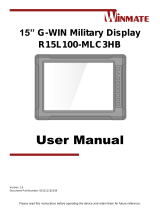
Full P67 Rugged Display
R15L100-67C3HB
G-Win Series
User Manual
Document Version 1.0
Document Part Number: 9152150I1007

2
15" G-Win Rugged Display User Manual
Contents
Preface .................................................................................................................................................... 3
About This User Manual ......................................................................................................................... 7
Chapter 1: Introduction .......................................................................................................................... 8
1.1 Introduction ............................................................................................................................. 9
1.3 Package Contents ................................................................................................................... 9
1.4 Description of Parts ............................................................................................................... 10
1.5 Physical Buttons and LED Indicators..................................................................................... 11
Chapter 2: Hardware Installation ......................................................................................................... 12
2.1 Cleaning the Monitor ............................................................................................................. 13
2.2 Wiring Requirements ............................................................................................................. 13
2.3 Connecting to Other Devices ................................................................................................ 14
2.4 Connector Description ........................................................................................................... 15
2.4.1 Power Input Connector ............................................................................................... 15
2.4.2 RS-232/ USB Connector for Touch ............................................................................. 16
2.4.3 VGA Connector ........................................................................................................... 17
2.4.4 DVI Connector ............................................................................................................ 18
2.4.5 Video Connector ......................................................................................................... 19
Chapter 3: Mounting ............................................................................................................................. 20
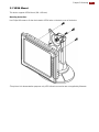
3.1 VESA Mount ......................................................................................................................... 21
3.2 Dash/ Yoke Mount ................................................................................................................. 22
Chapter 4: Operating the Device ......................................................................................................... 24
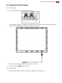
4.1 Turning On/ Off the Display ................................................................................................... 25
Appendix ............................................................................................................................................... 26
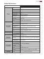
Product Specifications ................................................................................................................. 27

3
Preface
Preface
Copyright Notice
No part of this document may be reproduced, copied, translated, or transmitted in any form or by any
means, electronic or mechanical, for any purpose, without the prior written permission of the original
manufacturer.
Trademark Acknowledgement
Brand and product names are trademarks or registered trademarks of their respective owners.
Disclaimer
We reserve the right to make changes, without notice, to any product, including circuits and/or software
described or contained in this manual in order to improve design and/or performance. We assume no
responsibility or liability for the use of the described product(s) conveys no license or title under any
patent, copyright, or masks work rights to these products, and make no representations or warranties
that these products are free from patent, copyright, or mask work right infringement, unless otherwise
specified. Applications that are described in this manual are for illustration purposes only. We make no
representation or guarantee that such application will be suitable for the specified use without further
testing or modification.
Warranty
Our warranty guarantees that each of its products will be free from material and workmanship defects
for a period of one year from the invoice date. If the customer discovers a defect, we will, at his/her
option, repair or replace the defective product at no charge to the customer, provide it is returned during
the warranty period of one year, with transportation charges prepaid. The returned product must be
properly packaged in its original packaging to obtain warranty service. If the serial number and the
product shipping data differ by over 30 days, the in-warranty service will be made according to the
shipping date. In the serial numbers the third and fourth two digits give the year of manufacture, and the
fifth digit means the month (e. g., with A for October, B for November and C for December).
For example, the serial number 1W18Axxxxxxxx means October of year 2018.
Customer Service
We provide a service guide for any problem by the following steps: First, visit the website of our
distributor to find the update information about the product. Second, contact with your distributor, sales
representative, or our customer service center for technical support if you need additional assistance.
You may need the following information ready before you call:
Product serial number
Software (OS, version, application software, etc.)
Description of complete problem
The exact wording of any error messages
In addition, free technical support is available from our engineers every business day. We are always
ready to give advice on application requirements or specific information on the installation and
operation of any of our products.

4
15" G-Win Rugged Display User Manual
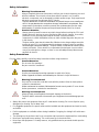
Advisory Conventions
Four types of advisories are used throughout the user manual to provide helpful information or to alert you
to the potential for hardware damage or personal injury. These are Notes, Important, Cautions, and
Warnings. The following is an example of each type of advisory. All cautions and warnings on the
equipment should be noted.
Note:
A note is used to emphasize helpful information
Important:
An important note indicates information that is important for you to know.
Caution/ Attention
A Caution alert indicates potential damage to hardware and explains how to avoid the
potential problem.
Une alerte d’attention indique un dommage possible à l’équipement et explique comment
éviter le problème potentiel.
Warning!/ Avertissement!
An Electrical Shock Warning indicates the potential harm from electrical hazards and how
to avoid the potential problem.
Un Avertissement de Choc Électrique indique le potentiel de chocs sur des emplacements
électriques et comment éviter ces problèmes.
Alternating Current ! / Mise à le terre !
The Protective Conductor Terminal (Earth Ground) symbol indicates the potential risk of
serious electrical shock due to improper grounding.
Le symbole de Mise à Terre indique le risqué potential de choc électrique grave à la
terre incorrecte.

5
Preface
Safety Information
Warning!/ Avertissement!
Always completely disconnect the power cord from your chassis whenever you work
with the hardware. Do not make connections while the power is on. Sensitive
electronic components can be damaged by sudden power surges. Only experienced
electronics personnel should open the PC chassis.
Toujours débrancher le cordon d’alimentation du chassis lorsque vous travaillez sur
celui-ci. Ne pas brancher de connections lorsque l’alimentation est présente. Des
composantes électroniques sensibles peuvent être endommagées par des sauts
d’alimentation. Seulement du personnel expérimenté devrait ouvrir ces chassis.
Caution/ Attention
Always ground yourself to remove any static charge before touching the CPU card.
Modern electronic devices are very sensitive to static electric charges. As a safety
precaution, use a grounding wrist strap at all times. Place all electronic
components in a static-dissipative surface or static-shielded bag when they are not
in the chassis.
Toujours verifier votre mise à la terre afin d’éliminer toute charge statique avant de
toucher la carte CPU. Les équipements électroniques moderns sont très sensibles
aux décharges d’électricité statique. Toujours utiliser un bracelet de mise à la terre
comme précaution. Placer toutes les composantes électroniques sur une surface
conçue pour dissiper les charge, ou dans un sac anti-statique lorsqu’elles ne sont
pas dans le chassis.
Safety Precautions
For your safety carefully read all the safety instructions before using the device.
Caution/Attention
Do not cover the openings!
Ne pas couvrir les ouvertures!
Caution/Attention
Use the recommended mounting apparatus to avoid risk of injury.
Utiliser l’appareil de fixation recommandé pour éliminer le risque de blessure.
Warning!/ Avertissement!
Only use the connection cords that come with the product. When in doubt, please
contact the manufacturer.
Utiliser seulement les cordons d’alimentation fournis avec le produit. Si vous doutez
de leur provenance, contactez le manufacturier.
Warning!/ Avertissement!
Always ground yourself against electrostatic damage to the device.
Toujours vérifier votre mise à la terre afin que l’équipement ne se décharge pas sur
vous.
Always disconnect this equipment from any AC outlet before cleaning. Do not use liquid or spray
detergents for cleaning. Use a damp cloth.
For pluggable equipment, the power outlet must be installed near the equipment and must be easily
accessible.
Put this equipment on a reliable surface during installation. Dropping it or letting it fall could cause
damage.
The openings on the enclosure are for air convection and to protect the equipment from overheating.
Never pour any liquid into an opening. This could cause fire or electrical shock.
Never open the equipment. For safety reasons, only qualified service personnel should open the
equipment.

6
15" G-Win Rugged Display User Manual
Important Information
Federal Communications Commission Radio Frequency Interface Statement
This device complies with part 15 FCC rules.
Operation is subject to the following two conditions:
This device may not cause harmful interference.
This device must accept any interference received including
interference that may cause undesired operation.
This equipment has been tested and found to comply with the limits for a class "B" digital device,
pursuant to part 15 of the FCC rules. These limits are designed to provide reasonable protection
against harmful interference when the equipment is operated in a commercial environment. This
equipment generates, uses, and can radiate radio frequency energy and, if not installed and used in
accordance with the instruction manual, may cause harmful interference to radio communications.
Operation of this equipment in a residential area is likely to cause harmful interference in which case
the user will be required to correct the interference at him own expense.
EC Declaration of Conformity
Electromagnetic Compatibility Directive (2014/30/EU)
EN55024: 2010 EN 55022: 2010 Class B
o IEC61000-4-2: 2009
o IEC61000-4-3: 2006+A1: 2007+A2: 2010
o IEC61000-4-4: 2012
o IEC61000-4-5: 2014
o IEC61000-4-6: 2013
o IEC61000-4-8: 2010
o IEC61000-4-11: 2004
EN55022: 2010/AC:2011
EN61000-3-2:2014
EN61000-3-3:2013
Low Voltage Directive (2014/35/EU)
EN 60950-1:2006/A11:2009/A1:2010/A12:2011/ A2:2013
This equipment is in conformity with the requirement of the following EU legislations and harmonized
standards. Product also complies with the Council directions.

7
About This User Manual
About This User Manual
This User Manual provides information about using the Winmate® 15-inch G-Win Rugged Display. This
User Manual applies to model number R15L100-67C3HB.
The documentation set for the 15-inch G-Win Rugged Display R15L100-67C3HB provides information for
specific user needs, and includes:
User Manual – contains detailed description on how to use the display, its components and
features.
Note:
Some pictures in this guide are samples and can differ from actual product.
Document Revision History
Version
Date
Note
1.0
13-Jul-2018
Initial document release

8
15" G-Win Rugged Display User Manual
Chapter 1: Introduction
This chapter gives you product overview, describes features and
hardware specification. You will find all accessories that come
with the Display in the packing list. Mechanical dimensions and
drawings included in this chapter.

9
Chapter 1: Introduction
1.1 Introduction
Congratulations on purchasing 15-inch G-Win Rugged Display R15L100-67C3HB. Winmate IP67 series
display is designed in a very robust and waterproof (IP67/NEMA 6) aluminum housing. Withstanding even
the highest demands of all-day field use, and protected against shock and vibration. The robust design fits
the demands for every harsh environment applications such as logistics, transportation/ fleet management,
heavy vehicles, utility and also outdoor usage.
Highlights
High Quality 15" XGA Panel, 1024x768 resolution
Full IP67-rated dust/ water protection
Bonding with anti-moisture treatment
Aluminum housing with anti-corrosion treatments
Shock and Vibration resistance according to MIL- STD-810G
Wide range 9~36V DC power input
5 Wire resistive touchscreen / anti-reflection protection glass(Optional)
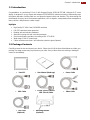
1.3 Package Contents
Carefully remove the box and unpack your device. Please check if all the items listed below are inside your
package. Package content may vary based on your order. If any of these items are missing or damaged
contact us immediately.
Panel PC
User Manual (Hardcopy)
Power Cable
VGA Cable
RS232 (Touch) Cable or
USB (Touch) Cable
Video Cable
DVI Cable
(Optional)
Mounting Bracket
(Optional)

10
15" G-Win Rugged Display User Manual
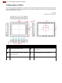
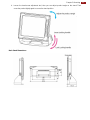
1.4 Description of Parts
This section describes appearance, connectors’ layout and mechanical dimensions of display. Notice that
this is a simplified drawing and some components are not marked in detail. Please contact our sales representative if
you need further product information.
Unit: mm
Dimensions: 398 x 308 x 58
№
Description
№
Description
❶
Power Connector (M21, 3 pin)
❹
RS-232 for Touch (M21, 10 pin) or USB for Touch
(M21, 10 pin)
❷
VGA Connector (M21, 10 pin) or optional
DVI (M21, 15 pin)
❺
DVI Connector (M21, 15 pin) (Optional)
❸
Video Connector (M21, 10 pin) (Optional)
❻
OSD Control Panel

11
Chapter 1: Introduction
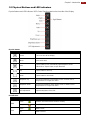
1.5 Physical Buttons and LED Indicators
Physical buttons and LED indicators (OSD Control Panel) located on the front side of the Display.
Physical Buttons
Icon
Button
Function
Power
Turn On or turn Off the Display.
Menu
Opens main menu.
Auto
Tap the button once to automatically adjust brightness mode.
In Main Menu: Tap the button to open Next item.
Up
Tap the button to move up.
Down
Tap the button to move down.
Brightness Up
Increase the brightness of the display screen, or allows user to
navigate items of a single OSD menu.
Brightness Down
Decrease the brightness of the display screen, or allows user to
navigate items of a single OSD menu.
LED Adjustment
Adjust the brightness of the LED.
LED Indicators
Indicator
Color
Definition
PWR
Green
Power is ON and the device functions normally.
Orange
Panel PC is suspended.
HDD
Green
HDD is active.
OFF
HDD is inactive.

12
15" G-Win Rugged Display User Manual
Chapter 2: Hardware Installation
This chapter provides hardware installation instructions, mounting
guide for all available mounting options. Pay attention to cautions and
warning to avoid any damages.

13
Chapter 2: Hardware Installation
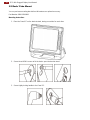
2.1 Cleaning the Monitor
Before cleaning:
Make sure the device is turned off.
Disconnect the power cable from any AC outlet.
When cleaning:
Never spray or pour any liquid directly on the screen or case.
Wipe the screen with a clean, soft, lint-free cloth. This removes dust and other particles.
The display area is highly prone to scratching. Do not use ketene type material (ex. Acetone), Ethyl
alcohol, toluene, ethyl acid or Methyl chloride to clear the panel. It may permanently damage the
panel and void the warranty.
If it is still not clean enough, apply a small amount of non-ammonia, non-alcohol based glass
cleaner onto a clean, soft, lint-free cloth, and wipe the screen.
Don not use water or oil directly on the display screen. If droplets are allowed to drop on the screen,
permanent staining or discoloration may occur.
2.2 Wiring Requirements
The following common safety precautions should be observed before installing any electronic device:
Strive to use separate, non-intersecting paths to route power and networking wires. If power wiring
and device wiring paths must cross make sure the wires are perpendicular at the intersection point.
Keep the wires separated according to interface. The rule of thumb is that wiring that shares similar
electrical characteristics may be bundled together.
Do not bundle input wiring with output wiring. Keep them separate.
When necessary, it is strongly advised that you label wiring to all devices in the system.
Do not run signal or communication wiring and power wiring in the same conduit. To avoid
interference, wires with different signal characteristics (i.e., different interfaces) should be routed
separately.
Be sure to disconnect the power cord before installing and/or wiring your device.
Verify the maximum possible current for each wire gauge, especially for the power cords. Observe
all electrical codes dictating the maximum current allowable for each wire gauge.
If the current goes above the maximum ratings, the wiring could overheat, causing serious damage
to your equipment.
Be careful when handling the unit. When the unit is plugged in, the internal components generate a
lot of heat which may leave the outer casing too hot to touch.

14
15" G-Win Rugged Display User Manual
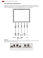
2.3 Connecting to Other Devices
This Display comes with various interfaces located on the bottom panel. All of these connectors have been
shipped with protective caps. To ensure the waterproof function can work properly, make sure that the
protective caps and have been securely tightened whenever the connectors are not used.
DVI Cable
(Optional)
RS-232/
USB
Cable for
Touch
Video
Cable
(Optional)
VGA
Power
Cable
Important
Please note that when reinstalling the protective cap, it must be fully tightened to ensure the unit is properly
sealed to meet the IP67 enclosure rating.

15
Chapter 2: Hardware Installation
2.4 Connector Description
The display features M21 type connectors with protective caps and has full IP67 rating.
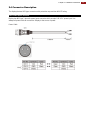
2.4.1 Power Input Connector
Display has M21 type 3 pin male power input connector which accepts 9-36 V DC power input. Use
waterproof power cable to connect the Display to the source of power.
Power Cable

16
15" G-Win Rugged Display User Manual
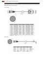
2.4.2 RS-232/ USB Connector for Touch
Display has M21 type 10 pin male RS-232 or USB connector for touch based on your order. Use waterproof
serial/ USB cable to connect the touch.
RS-232 Cable
USB Cable

17
Chapter 2: Hardware Installation
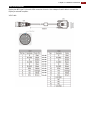
2.4.3 VGA Connector
Display has M21 type 10 pin male VGA connector for touch. Use waterproof serial cable to connect the
Display to external computer.
VGA Cable

18
15" G-Win Rugged Display User Manual
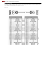
2.4.4 DVI Connector
The Display has M21 type15 pin video connector. Use waterproof DVI cable to connect the Display to the
source of video. Notice that DVI is an optional connector.
DVI Cable

19
Chapter 2: Hardware Installation
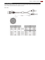
2.4.5 Video Connector
The Display has M21 type10 pin video connector. Use waterproof Video cable to connect the Display to the
source of video. Notice that Video is an optional connector.
Video Cable

20
15" G-Win Rugged Display User Manual
Chapter 3: Mounting
This chapter describes how to mount the device.
La page est en cours de chargement...
La page est en cours de chargement...
La page est en cours de chargement...
La page est en cours de chargement...
La page est en cours de chargement...
La page est en cours de chargement...
La page est en cours de chargement...
La page est en cours de chargement...
-
 1
1
-
 2
2
-
 3
3
-
 4
4
-
 5
5
-
 6
6
-
 7
7
-
 8
8
-
 9
9
-
 10
10
-
 11
11
-
 12
12
-
 13
13
-
 14
14
-
 15
15
-
 16
16
-
 17
17
-
 18
18
-
 19
19
-
 20
20
-
 21
21
-
 22
22
-
 23
23
-
 24
24
-
 25
25
-
 26
26
-
 27
27
-
 28
28


Winmate G-Win Series Manuel utilisateur
- Taper
- Manuel utilisateur
- Ce manuel convient également à
dans d''autres langues
- English: Winmate G-Win Series User manual
Documents connexes
-
 Winmate R15L100-VMC3HB Manuel utilisateur
-
 Winmate R15L100-MLC3HB Manuel utilisateur
-
 Winmate R15IB3S-67A3HB Guide de démarrage rapide
-
 Winmate G-WIN Manuel utilisateur
-
 Winmate R15L100-GCC3 Guide de démarrage rapide
-
 Winmate W22L100-SPA3 Guide de démarrage rapide
-
 Winmate W22L100-GCA3 Manuel utilisateur
-
 Winmate M101M8 Series Manuel utilisateur
-
 Winmate R15IH3S-67A3 Guide de démarrage rapide
-
 Winmate G-Win Series Guide de démarrage rapide


