
Page 1
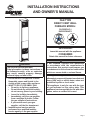
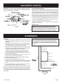
FAN TYPE
DIRECT
-
VENT WALL
FURNACE MODEL:
DVC55IPXLP-1
DVC55IPXNAT-1
WARNING
FIRE OR EXPLOSION HAZARD
If the information in these instructions is
not followed exactly, a re or explosion
may result causing property damage,
personal injury or loss of life.
— Do not store or use gasoline or other
ammable vapors and liquids in the
vicinity of this or any other appliance.
— WHAT TO DO IF YOU SMELL GAS
• Do not try to light any appliance.
• Do not touch any electrical switch;
do not use any phone in your building.
• Leave the building immediately.
• Immediately call your gas supplier
from a neighbor’s phone. Follow
the gas supplier’s instructions.
• If you cannot reach your gas
supplier, call the re department.
— Installation and service must be
performed by a qualied installer,
service agency or the gas supplier.
INSTALLER:
Leave this manual with the appliance.
CONSUMER:
Retain this manual for future reference.
WARNING
If not installed, operated and maintained
in accordance with the manufacturer's
instructions, this product could expose you
to substances in fuel or from fuel combustion
which can cause death or serious illness.
This appliance may be installed in an
aftermarket, permanently located, manufactured
home (USA only) or mobile home, where not
prohibited by state or local codes.
This appliance is only for use with the type
of gas indicated on the rating plate. This
appliance is not convertible for use with other
gases, unless a certied kit is used.
INSTALLATION INSTRUCTIONS
AND OWNER’S MANUAL

37403-5-0620Page 2
TABLE OF CONTENTS
Important Safety Information .......................................................................................................3
Safety Information for Users of Propane Gas ..............................................................................4
Requirements for Massachusetts ................................................................................................5
Introduction .............................................................................................................................. 6-7
Specications ............................................................................................................................... 7
Gas Supply .............................................................................................................................. 8-9
Clearances .................................................................................................................................. 9
Installation Instructions ........................................................................................................ 10-12
Lighting Instructions ..................................................................................................................13
Pilot Flame Characteristics .......................................................................................................14
Main Burner Flame Characteristics ..........................................................................................14
Wiring ......................................................................................................................................... 15
Service and Maintenance Suggestions ............................................................................... 16-17
Troubleshooting ................................................................................................................... 18-20
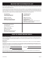
Master Parts Distributor List ......................................................................................................21
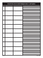
How To Order Repair Parts ........................................................................................................ 21
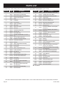
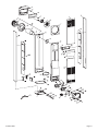
Parts List ...................................................................................................................................22
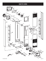
Parts View ..................................................................................................................................23
Warranty ....................................................................................................................................24
SECTION PAGE

37403-5-0620 Page 3
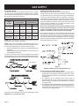
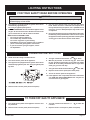
THIS IS A HEATING APPLIANCE
DO NOT OPERATE THIS APPLIANCE WITHOUT FRONT PANEL INSTALLED.
• Due to high temperatures the appliance should be
located out of trafc and away from furniture and
draperies.
• Children and adults should be alerted to the hazards
of high surface temperatures and should stay away
to avoid burns or clothing ignition.
• Young children should be carefully supervised when
they are in the same room as the appliance.
• Clothing or other ammable material should not be
placed on or near the appliance.
• Any safety screen or guard removed for servicing
an appliance must be replaced prior to operating
the appliance.
• Keep burner and control compartment clean.
• Vent cap hot while furnace is in operation.
• Installation and repair should be done by a QUALI-
FIED SERVICE PERSON. The appliance should be
inspected before use and at least annually by a
qualied service person. More frequent cleaning
may be required due to excessive lint from carpet-
ing, bedding materials, etc. It is imperative that
control compartments, burners and circulating air
passageways of the appliance be kept clean.
• DO NOT put anything around the furnace that will
obstruct the ow of combustion and ventilation air.
• DO keep the appliance area clear and free from
combustible material, gasoline and other ammable
vapors and liquids.
• DO examine venting system periodically and replace
damaged parts.
• DO make a periodic visual check of pilot and burn-
ers. Clean and replace damaged parts.
• CAUTION: Pilot hole cover must be kept tightly
closed during operation.
• DO NOT use this heater if any part has been under
water. Immediately call a qualied service techni-
cian to inspect the heater and to replace any part of
the control system and any gas control which has
been under water.
IMPORTANT SAFETY INFORMATION

37403-5-0620Page 4
SAFETY INFORMATION FOR USERS OF PROPANE GAS
Propane is a ammable gas which can cause res and explo-
sions. In its natural state, propane is odorless and colorless.
You may not know all the following safety precautions which
can protect both you and your family from an accident. Read
them carefully now, then review them point by point with the
members of your household. Someday when there may not
be a minute to lose, everyone's safety will depend on knowing
exactly what to do. If, after reading the following information,
you feel you still need more information, please contact your
gas supplier.
PROPANE GAS WARNING ODOR
If a gas leak happens, you should be able to smell the gas
because of the odorant put in the Propane Gas. That's your
signal to go into immediate action!
• Do not operate electric switches, light matches, use your phone.
Do not do anything that could ignite the gas.
• Get everyone out of the building, vehicle, trailer, or area. Do
that IMMEDIATELY.
• Close all gas tank or cylinder supply valves.
• Propane Gas is heavier than air and may settle in low areas
such as basements. When you have reason to suspect a gas
leak, keep out of basements and other low areas. Stay out until
reghters declare them to be safe.
• Use your neighbor's phone and call a trained Propane Gas
service person and the re department. Even though you may
not continue to smell gas, do not turn on the gas again. Do not
re-enter the building, vehicle, trailer, or area.
• Finally, let the service man and reghters check for escaped
gas. Have them air out the area before you return. Properly
trained Propane Gas service people should repair the leak,
then check and relight the gas appliance for you.
NO ODOR DETECTED - ODOR FADE
Some people cannot smell well. Some people cannot smell the
odor of the chemical put into the gas. You must nd out if you can
smell the odorant in propane. Smoking can decrease your ability to
smell. Being around an odor for a time can affect your sensitivity or
ability to detect that odor. Sometimes other odors in the area mask
the gas odor. People may not smell the gas odor or their minds are
on something else. Thinking about smelling a gas odor can make
it easier to smell.
The odorant in Propane Gas is colorless, and it can fade under some
circumstances. For example, if there is an underground leak, the
movement of the gas through soil can lter the odorant. Odorants
in Propane Gas also are subject to oxidation. This fading can occur
if there is rust inside the storage tank or in iron gas pipes.
The odorant in escaped gas can adsorb or absorb onto or into
walls, masonry and other materials and fabrics in a room. That will
take some of the odorant out of the gas, reducing its odor intensity.
Propane Gas may stratify in a closed area, and the odor intensity
could vary at different levels. Since it is heavier than air, there may
be more odor at lower levels. Always be sensitive to the slightest gas
odor. If you detect any odor, treat it as a serious leak. Immediately
go into action as instructed earlier.
SOME POINTS TO REMEMBER
• Learn to recognize the odor of Propane Gas. Your local Propane
Gas Dealer can give you a "Scratch and Sniff" pamphlet. Use
it to nd out what the propane odor smells like. If you suspect
that your Propane Gas has a weak or abnormal odor, call your
Propane Gas Dealer.
• If you are not qualied, do not light pilot lights, perform service,
or make adjustments to appliances on the Propane Gas system.
If you are qualied, consciously think about the odor of Propane
Gas prior to and while lighting pilot lights or performing service
or making adjustments.
• Sometimes a basement or a closed-up house has a musty
smell that can cover up the Propane Gas odor. Do not try to
light pilot lights, perform service, or make adjustments in an
area where the conditions are such that you may not detect
the odor if there has been a leak of Propane Gas.
• Odor fade, due to oxidation by rust or adsorption on walls of
new cylinders and tanks, is possible. Therefore, people should
be particularly alert and careful when new tanks or cylinders
are placed in service. Odor fade can occur in new tanks, or
reinstalled old tanks, if they are lled and allowed to set too
long before relling. Cylinders and tanks which have been out
of service for a time may develop internal rust which will cause
odor fade. If such conditions are suspected to exist, a periodic
sniff test of the gas is advisable. If you have any question about
the gas odor, call your Propane Gas Dealer. A periodic sniff
test of the Propane Gas is a good safety measure under any
condition.
• If, at any time, you do not smell the Propane Gas odorant and
you think you should, assume you have a leak. Then take the
same immediate action recommended above for the occasion
when you do detect the odorized Propane Gas.
• If you experience a complete "gas out," (the container is under
no vapor pressure), turn the tank valve off immediately. If the
container valve is left on, the container may draw in some air
through openings such as pilot light orices. If this occurs, some
new internal rusting could occur. If the valve is left open, then
treat the container as a new tank. Always be sure your con-
tainer is under vapor pressure by turning it off at the container
before it goes completely empty or having it relled before it is
completely empty.

37403-5-0620 Page 5
REQUIREMENTS FOR MASSACHUSETTS
For all side wall horizontally vented gas fueled equipment installed
in every dwelling, building or structure used in whole or in part for
residential purposes, including those owned or operated by the
Commonwealth and where the side wall exhaust vent termination
is less than seven (7) feet above nished grade in the area of the
venting, including but not limited to decks and porches, the following
requirements shall be satised:
1. INSTALLATION OF CARBON MONOXIDE DETECTORS. At
the time of installation of the side wall horizontal vented gas fu-
eled equipment, the installing plumber or gastter shall observe
that a hard wired carbon monoxide detector with an alarm and
battery back-up is installed on the oor level where the gas
equipment is to be installed. In addition, the installing plumber
or gastter shall observe that a battery operated or hard wired
carbon monoxide detector with an alarm is installed on each
additional level of the dwelling, building or structure served by
the side wall horizontal vented gas fueled equipment. It shall be
the responsibility of the property owner to secure the services
of qualied licensed professionals for the installation of hard
wired carbon monoxide detectors
a.
In the event that the side wall horizontally vented gas fueled
equipment is installed in a crawl space or an attic, the hard
wired carbon monoxide detector with alarm and battery
back-up may be installed on the next adjacent oor level.
b. In the event that the requirements of this subdivision can not
be met at the time of completion of installation, the owner
shall have a period of thirty (30) days to comply with the
above requirements; provided, however, that during said
thirty (30) day period, a battery operated carbon monoxide
detector with an alarm shall be installed.
2. APPROVED CARBON MONOXIDE DETECTORS. Each carbon
monoxide detector as required in accordance with the above
provisions shall comply with NFPA 720 and be ANSI/UL 2034
listed and IAS certied.
3. SIGNAGE. A metal or plastic identication plate shall be per-
manently mounted to the exterior of the building at a minimum
height of eight (8) feet above grade directly in line with the
exhaust vent terminal for the horizontally vented gas fueled
heating appliance or equipment. The sign shall read, in print size
no less than one-half (1/2) inch in size, “GAS VENT DIRECTLY
BELOW. KEEP CLEAR OF ALL OBSTRUCTIONS”.
4. INSPECTION. The state or local gas inspector of the side wall
horizontally vented gas fueled equipment shall not approve
the installation unless, upon inspection, the inspector observes
carbon monoxide detectors and signage installed in accordance
with the provisions of 248 CMR 5.08(2)(a) 1 through 4.
(b) EXEMPTIONS: The following equipment is exempt from
248 CMR 5.08(2)(a)1 through 4:
1. The equipment listed in Chapter 10 entitled “Equip-
ment Not Required To Be Vented” in the most current
edition of NFPA 54 as adopted by the Board; and
2. Product Approved side wall horizontally vented gas
fueled equipment installed in a room or structure
separate from the dwelling, building or structure used
in whole or in part for residential purposes.
(c) MANUFACTURER REQUIREMENTS - GAS EQUIPMENT
VENTING SYSTEM PROVIDED. When the manufacturer of
Product Approved side wall horizontally vented gas equip-
ment provides a venting system design or venting system
components with the equipment, the instructions provided
by the manufacturer for installation of the equipment and
the venting system shall include:
1. Detailed instructions for the installation of the venting
system design or the venting system components; and
2. A complete parts list for the venting system design or
venting system.
(e) A copy of all installation instructions for all Product Approved
side wall horizontally vented gas fueled equipment, all
venting instructions, all parts lists for venting instructions,
and/or all venting design instructions shall remain with the
appliance or equipment at the completion of the installation.

37403-5-0620Page 6
Always consult your local Building Department regarding regulations,
codes or ordinances which apply to the installation of a direct vent
wall furnace.
Instructions to Installer
1.
Installer must leave instruction manual with owner after installation.
2. Installer must have owner ll out and mail warranty card supplied
with furnace.
3. Installer should show owner how to start and operate furnace.
WARNING
Any change to this furnace or its control can be dangerous.
This is a heating appliance and any panel, door or guard
removed for servicing an appliance must be replaced prior
to operating the appliance.
To Conserve Gas: Turn off pilot when heater is not in use.
General Information
This furnace is design certied in accordance with American National
Standard/CSA Standard Z21.86 and CSA 2.32 by the Canadian
Standards Association, as a fan type direct vent wall furnace to be
installed according to these instructions.
Any alteration of the original design, installed other than as
shown in these instructions or use with a type of gas not
shown on the rating plate is the responsibility of the person
and company making the change.
Important
All correspondence should refer to complete Model Number, Serial
Number and type of gas.
NOTICE: During initial ring of this unit, its paint will bake out and
smoke will occur. To prevent triggering of smoke alarms, ventilate
the room in which the unit is installed.
Installation on Rugs and Tile
If this appliance is installed directly on carpeting, tile or other
combustible material other than wood ooring the appliance shall
be installed on a metal or wood panel extending the full width and
depth of the appliance.
The base referred to above does not mean the re-proof base as
used on wood stoves. The protection is for rugs that are extremely
thick and light colored tile.
Installation in Residential Garages
Gas utilization equipment in residential garages shall be installed
so that all burners and burner ignition devices are located not less
than 18" above the oor.
Such equipment shall be located, or protected, so it is not subject
to physical damage by a moving vehicle.
Qualied Installing Agency
Installation and replacement of gas piping, gas utilization equipment
or accessories and repair and servicing of equipment shall be
performed only by a qualied agency. The term "qualied agency"
means any individual, rm, corporation or company which either in
person or through a representative is engaged in and is responsible for
(a) the installation or replacement of gas piping or (b) the connection,
installation, repair or servicing of equipment, who is experienced in
such work, familiar with all precautions required and has complied
with all the requirements of the authority having jurisdiction.
Commonwealth of Massachusetts: The installation must be
made by a licensed plumber or gas tter in the Commonwealth
of Massachusetts.
The installation must conform with local codes or, in the absence of
local codes, with the National Fuel Gas Code ANSI Z223.1/NFPA
54* Natural Gas and Propane Installation Code, CSA B149.1.
*Available from the American National Standards Institute, Inc., 11
West 42nd St., New York, N.Y. 10036.
High Altitudes
For altitudes/elevations above 2,000 feet (610m), input ratings should
be reduced at the rate of 4 percent for each 1,000 feet (305m) above
sea level. Canadian High Altitudes for locations having an elevation
above mean sea level between 2,000 feet (610m) and 4,500 feet
(1370m), the manifold pressure is to be decreased from 3.5" w.c.
(.871kPa) to 2.8" w.c. (.697kPa) for Natural Gas and from 10.0" w.c.
(2.49kPa) to 8.0" w.c. (1.992kPa) for Propane Gas.
Well Head Gas Installations
Some natural gas utilities use “well head” gas. This may affect
the Btu output of the unit and promote sooting. Units shall not be
converted to use well head gas.
INTRODUCTION

37403-5-0620 Page 7
INTRODUCTION (CONT'D)
MODEL DVC-55IP
Input BTU/HR 55,000
Height 82 3/8"
Width 16"
Depth 11 1/2"
Gas Inlet 1/2" Pipe
CFM 400
ACCESSORIES
SOR-1 Register, Side Outlet
SOK-1 Side Outlet Kit, 10" Boot Assembly w/Register
VINYL SIDING VENT KITS
Part Numbers Description
DV-822 Vinyl Siding Vent Kit
VSK2 Vinyl Siding Vent Kit
SPECIFICATIONS
CONVERSION KITS
Part Numbers Description Used On
682160 Propane to Natural DVC55IPXLP-1
682269 Natural to Propane DVC55IPXNAT-1
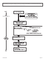
When an existing Category 1 heater is removed or replaced,
the original venting system may no longer be sized to
properly vent the attached appliances. Instructions shall
also indicate effects of an improperly sized venting system
(formation of condensate, leakage, spillage, etc.) and shall
specify the following test procedure:
WARNING
CARBON MONOXIDE POISONING HAZARD
Failure to follow the steps outlined below for each
appliance connected to the venting system being
placed into operation could result in carbon monoxide
poisoning or death.
The following steps shall be followed for each
appliance connected to the venting system being
placed into operation, while all other appliances
connected to the venting system are not in operation:
1. Seal any unused openings in the venting system.
2. Inspect the venting system for proper size and
horizontal pitch, as required in the National Fuel
Gas Code, ANSI Z223.1/NFPA 54 or the Natural
Gas and Propane Installation Code, CSA B149.1
and these instructions. Determine that there is no
blockage or restriction, leakage, corrosion and
other deciencies which could cause an unsafe
condition.
3. As far as practical, close all building doors and
windows and all doors between the space in which
the appliance(s) connected to the venting system
are located and other spaces of the building.
4. Close replace dampers.
5. Turn on clothes dryers and any appliance not
connected to the venting system. Turn on any
exhaust fans, such as range hoods and bathroom
exhausts, so they are operating at maximum
speed. Do operate a summer exhaust fan.
6. Follow the lighting instructions. Place the appliance
being inspected into operation. Adjust the
thermostat so appliance is operating continuously.
7. Test for spillage from draft hood equipped
appliances at the draft hood relief opening after 5
minutes of main burner operation. Use the ame
of a match or candle.
8. If improper venting is observed during any of the
above tests, the venting system must be corrected
in accordance with National Fuel Gas Code, ANSI
Z223.1/NFPA 54 and/or Natural Gas and Propane
Installation Code, CSA B149.1.
9. After is has been determined that each appliance
connected
to the venting system properly vents
when tested as outlined above, return doors,
windows, exhaust fans, replace dampers and
any other gas-red burning appliance to their
previous conditions of use.

37403-5-0620Page 8
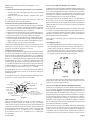
Locating Gas Supply
The gas line can enter the unit either through the oor or outside
wall. The gas line opening should be made at this time. Location
of the opening will be determined by the position of oor joists and
the valve and union used for servicing.
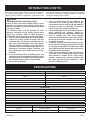
RECOMMENDED GAS PIPE DIAMETER
Pipe
Length
Schedule 40 Pipe
Inside Diameter
Tubing, Type L
Outside Diameter
Natural Propane Natural Propane
0-10 feet
0-3 meters
1/2”
12.7 mm
3/8”
9.5mm
1/2”
12.7 mm
3/8”
9.5 mm
10-40 feet
4-12 meters
1/2”
12.7 mm
1/2”
12.7mm
5/8”
15.9 mm
1/2”
12.7 mm
40-100 feet
13-30 meters
1/2”
12.7 mm
1/2”
12.7mm
3/4”
19 mm
1/2”
12.7 mm
100-150 feet
31-46 meters
3/4”
19 mm
1/2”
12.7 mm
7/8”
22.2 mm
3/4”
19 mm
NOTE: Never use plastic pipe. Check to conrm whether your local
codes allow copper tubing or galvanized.
NOTE: Since some municipalities have additional local codes, it
is always best to consult your local authority and installation code.
The use of the following gas connectors is recommended:
— ANS Z21.24 Appliance Connectors of Corrugated Metal Tubing
and Fittings
— ANS Z21.45 Assembled Flexible Appliance Connectors of Other
Than All-Metal Construction
The above connectors may be used if acceptable by the authority
having jurisdiction. The Commonwealth of Massachusetts requires
that a exible appliance connector cannot exceed three feet in length.
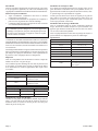
NPT NIPPLE
Figure 1
Consult the current National Fuel Gas Code, ANSI Z223.1 CAN/
CGA-B149 (.1 or .2) installation code.
GAS SUPPLY
Installing a New Main Gas Shut-Off
Each appliance should have its own manual gas shut-off.
A manual main gas shut-off should be located in the vicinity of the
unit. Where none exists, or where its size or location is not adequate,
contact your local authorized installer for installation or relocation.
Compounds used on threaded joints of gas piping shall be resistant
to the action of liqueed petroleum gases. The gas lines must be
checked for leaks by the installer. This should be done with a soap
solution watching for bubbles on all exposed connections, and if
unexposed, a pressure test should be made.
Never use an exposed ame to check for leaks. Appliance must
be disconnected from piping at inlet of control valve and pipe
capped or plugged for pressure test. Never pressure test with
appliance connected; control valve will sustain damage!
A gas valve and ground joint union should be installed in the gas
line upstream of the gas control to aid in servicing. It is required by
the National Fuel Gas Code that a drip line be installed near the gas
inlet. This should consist of a vertical length of pipe tee connected
into the gas line that is capped on the bottom in which condensation
and foreign particles may collect.
Figure 2
Method of Installing a Tee Fitting Sediment Trap
Pressure Testing of the Gas Supply System
1. To check the inlet pressure to the gas valve, a 1/8" (3mm) N.P.T.
plugged tapping, accessible for test gauge connection, must be
placed immediately upstream of the gas supply connection to
the appliance.
2. The appliance and its individual shut-off valve must be
disconnected from the gas supply piping system during any
pressure testing of that system at test pressures in excess of
1/2 psig (3.5 kPa).
3. The appliance must be isolated from the gas supply piping system
by closing its individual manual shut-off valve during any pressure
testing of the gas supply piping system at test pressures equal
to or less than 1/2 psig (3.5 kPa).

37403-5-0620 Page 9
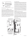
Clearances
1. In selecting a location for installation, it is necessary to provide
adequate accessibility clearances for servicing and proper
installation.
2. The DVC-55 minimum wall depth is 4-1/2 inches and maximum
wall depth is 13 inches. The use of tubes not supplied by the
manufacturer results in unsatisfactory performance.
3. The DVC-55 can be attached to the wall or recessed into the
wall up to 4 inches in depth but the minimum 4-1/2 inches vent/
air intake system wall depth must be maintained.
Example: If furnace is recessed into the wall at a depth of
4 inches, the minimum wall depth must be 8-1/2 inches.
4. The wall in which the furnace is recessed has (0) zero clearance
to the furnace sides and top.
5. When using side discharge registers, SOR-1 or SOK-1, the
furnace cannot be recessed into the wall.
6. Clearance to sidewall or combustible material is 4 inches.
7. Ceiling clearance is 4 inches.
8. Floor and rear wall clearance is (0) zero inches.
9. Clearance of 18 inches is required to sidewall or combustible
material when ush mounted SOR-1, side outlet register is
used.
10. The minimum distance from the center of the vent cap to the
nearest outside corner or obstruction is 24 inches.
The vent terminal of a direct vent appliance with an input over 50,000
BTU per hour shall be located at least 12 inches from any opening
through which ue gases could enter a building. The bottom of the
vent terminal and the air intake shall be located at least 12 inches
above grade.
WARNING: The nearest point of the vent cap should be a
minimum horizontal distant of six (6) feet from any pres-
sure regulator. In case of regulator malfunction, the six
(6) feet distance will reduce the chance of gas entering the
vent cap.
Figure 4
CLEARANCES
Attention! If one of the above procedures results in pressures in
excess of 1/2 psig (14" w.c.) (3.5 kPa) on the appliance gas valve,
it will result in a hazardous condition.
Figure 3
Checking Manifold Pressure
Both Propane and Natural Gas valves have a built-in pressure
regulator in the gas valve. Natural Gas models will have a manifold
pressure of approximately 3.5" w.c. at the valve outlet with the inlet
pressure to the valve from a minimum of 5.0" w.c. for the purpose of
input adjustment to a maximum of 7.0" w.c. Propane Gas models
will have a manifold pressure approximately 10.0" w.c. at the valve
outlet with the inlet pressure to the valve from a minimum of 11.0"
w.c. for the purpose of input adjustment to a maximum of 13.0" w.c.
A 1/8" N.P.T. plugged tapping, accessible for test gauge connection,
is located on the outlet side of the gas control.
The built-in regulator comes on at approximately 1/4th pressure
and full on in 10 seconds.
Safety Lockout
S8600H module provides 100 percent shutoff, or safety
lockout. If the pilot fails to light within 90 seconds, the
control system will shut down. The control system must be
reset by turning off power to the module for one minute.
GAS SUPPLY (CONT'D)

37403-5-0620Page 10
INSTALLATION INSTRUCTIONS
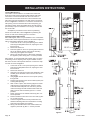
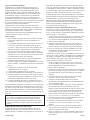
Locating Wall Opening
The furnace is to be located on an outside wall. Locate wall
studs so that wall opening will be located between wall studs.
The furnace is 16 inches in width and normal 16 inches on
center studs will not allow the furnace to be recessed into the
wall unless a stud is repositioned. The wall opening required as
shown in Figure 5 is a diameter of 7-1/2 inches. Locate and cut
wall opening. If there is insulation above the wall opening (air
inlet tube) a barrier should be installed above the wall opening
(air inlet tube) to prevent insulation from coming in contact with
the air inlet tube.
A template is provided in furnace carton for positioning
furnace on the wall. Also, refer to Figure 5 for positioning the
furnace on wall and for locating gas line connection.
Installing Optional Side Outlets
Side outlet register, SOR-1 may be installed on one or both sides
of the furnace at the required clearances of 18 inches to adjacent
wall or combustible material as shown in Figure 4.
1. Locate and cut the 5-1/2" square opening in the cabinet
side using the template from the kit, exposing the inner
liner knock-out.
2. Remove the knock-out.
3. Place the register on the 5-1/2" opening with the louvers
set for the desired direction and mark the mounting
holes using the register as a template.
4. Drill (2) 1/8" diameter holes in cabinet side and fasten
the register in place with (2) #10 x 1" screws provided.
Side outlet kit, 10" boot assembly with register, SOK-1 for warm
air discharge into an adjoining room may be installed on either
side of the furnace at the required clearance of 4 inches to adja-
cent wall as shown in Figure 7.
1. Locate and cut the 5-1/2" square opening in the cabinet
side using the template from the kit, exposing the inner
liner knock-out.
2. Remove the knock-out.
3. Using the inner and outer boots as hole templates, mark
and drill (8) 1/8" diameter holes in the inner liner and
cabinet side.
4. Using Figure 7 locate and cut a 6-3/4" square opening
through walls.
5. Prepare wall opening for the vent-air intake system (see
Locating Wall Opening).
6. With furnace in place, after checking alignment of side
outlet opening in wall and furnace, place the 9-3/8" x
9-3/8" side outlet wall plate over outer boot, pass the
outer boot through the wall and attach side outlet wall
plate to furnace side of wall with (2) #10 x 1" screws
provided.
7. Fasten outer boot to the cabinet side with (4) #8 x 1/4"
screws provided.
8. Position and attach inner boot to inner liner with (4) #8 x
1/4" screws provided.
9. Locate the register with its louvers positioned for the
desired air discharge direction and mark the mounting
holes using the register as a template.
10. Drill (2) 1/8" diameter holes in the wall and fasten the
register in place with (2) #10 x 1" screws provided.
Figure 5
Figure 6 Figure 7

37403-5-0620 Page 11
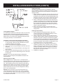
Figure 8
Locating Electric Supply
A 7/8" diameter knockout is provided at the bottom of the left and
right side panels. A three-prong (grounding) plug assembly is
located within the control compartment (bottom) of the furnace.
Please remove 7/8" knockout from appropriate side panel when
routing plug assembly to an electrical outlet.
Installation of Three-prong (Grounding) Plug Assembly
1. Disconnect nylon cap on 3' plug assembly from nylon plug
on wiring harness. Remove 3' plug assembly from control
compartment (bottom) of the furnace.
2. Remove 7/8" knockout from appropriate side panel.
3. Insert nylon cap on 3' plug assembly into the 7/8" hole in the
side panel.
4. Connect nylon cap on 3' plug assembly to nylon plug on the
wiring harness.
5. Place 7/8" strain relief bushing around the cord of the 3' plug
assembly. Insert 7/8" strain relief bushing into the 7/8" hole in
the side panel.
Attention! The 7/8" strain relief bushing is located within
the same yellow envelope as the Installation Instructions and
Owner's Manual.
Attaching Furnace to Wall
Refer to Figure 4 for the location of the 7-1/2" diameter wall
opening for the furnace. After the wall opening has been located
and cut, position ue outlet on furnace in center of wall open-
ing. When attaching furnace to the wall remove that portion of
baseboard and molding on the wall which is behind the furnace.
Attach furnace to wall, at the outer casing top, with (2) toggle
bolts provided and to oor, at the outer casing bottom, with (2)
#10 x 1-1/2" screws provided.
Attention! The screw holes on the outer casing bottom are
off-set above the oor approximately 3/8". Do not over-tighten
screws and distort the off-set on the outer casing bottom. Distor-
tion of the outer casing bottom will not allow the lower front panel
to be attached to the furnace.
INSTALLATION INSTRUCTIONS (CONT'D)
Cutting Vent Tubes
This is the most important part of the installation. With the
furnace installed on wall the 6" diameter air inlet tube and the 4"
diameter ue outlet tube are to be marked and cut using the fol-
lowing procedure.
1. Attach 6" diameter air inlet tube onto the collar of air drop as-
sembly. Be sure 6" diameter air inlet tube is placed as far as
possible onto the collar of the air drop assembly. Mark the 6"
diameter air inlet tube 1/2" beyond the outside wall. Remove
6" diameter air inlet tube from collar of air drop assembly.
2. Attach 4" diameter ue outlet tube onto ue outlet collar on
combustion chamber. Be sure 4" diameter ue outlet tube is
placed as far as possible onto the collar of ue outlet. Mark
the 4" diameter ue outlet tube 2-1/4" beyond the outside
wall. Remove 4" diameter ue outlet tube from collar of ue
outlet on combustion chamber.
3. Mark or wrap tape completely around the tubes at the
marked points to help in making a true cut. Do not crimp or
enlarge tubes.
Installing Vent Assembly
1. Place caulking (not provided) beneath the edge of the
outside mounting plate. Use additional caulking to correct
uneven wall surface, such as clapboard.
2. Attach 6" diameter air inlet tube onto the collar of air drop
assembly. Attach caulked, outside mounting plate into the 6"
diameter air inlet tube. Position the outside mounting plate
so that 6" diameter air inlet tube has a slight downward slope
to the outside. The downward slope is necessary to prevent
the entry of rainwater. Attach outside mounting plate to exte-
rior wall with (4) #10 x 1-1/2" screws provided.
3. Apply furnace cement to 4" diameter ue outlet collar on
combustion chamber and to 4" diameter collar on vent cap.
Attach 4" diameter ue outlet tube onto ue outlet collar on
combustion chamber. Attach vent cap into the 4" diameter
ue outlet tube. Attach vent cap to outside mounting plate
with (3) #10 x 1/2" screws provided.
4. Installation is completed.

37403-5-0620Page 12
INSTALLATION INSTRUCTIONS (CONT'D)
Reassembly And Resealing Vent-Air Intake System
When vent-air intake system is removed for servicing the furnace,
the following steps will assure proper reassembly and resealing
of the vent-air intake assembly.
1. Remove old caulking beneath the edge of the outside
mounting plate. Apply new caulking beneath the edge of the
outside mounting plate. Use additional caulking to correct
uneven wall surface, such as clapboard.
2. Remove old furnace cement from ue outlet collar on com-
bustion chamber and collar of vent cap. Remove old furnace
cement from both ends of 4" diameter ue outlet tube.
3. Attach 6" diameter air inlet tube onto the collar of air drop
assembly. Attach caulked, outside mounting plate into the 6"
diameter air inlet tube. Position the outside mounting plate
so that 6" diameter air inlet tube has a slight downward slope
to the outside. The downward slope is necessary to pre-
vent the entry of rainwater. Attach outside mounting plate
to exterior wall with (4) #10 x 1" screws provided.
4. Apply furnace cement to 4" diameter ue outlet collar on
combustion chamber and to 4" diameter collar on vent cap.
Attach 4" diameter ue outlet tube onto ue outlet collar on
combustion chamber. Attach vent cap into the 4" diameter
ue outlet tube. Attach vent cap to outside mounting plate
with (3) #10 x 1/2" screws provided.
5. Reassembly and resealing vent-air intake system is com-
pleted.
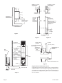
Installing a Vent Near a Window Ledge,
Other Type of Projection or on Siding (vinyl, aluminum, etc.)
Direct vent furnaces are designed to be installed on a uniform
outside wall. When the wind comes from any angle (up, down or
from either side), it must hit the vent cap equally over both the air
inlet and the ue outlet portions of the vent. Any wall projection,
such as a door or window casing, which disturbs the wind on one
side of the air inlet section will result in back pressure on the ue
section smothering the ame and eventual pilot outage.
When the vent cap is to be installed on siding or it appears that a
projection within 6" of any side of the air inlet section could shield
the air inlet section, the entire vent should be supported away
from the wall at least the distance of the projection. 2" x 4" fram-
ing whose outside dimensions match the overall dimensions of
the mounting plate is recommended. The 2" x 4" framing protects
siding from possible warpage or discoloration. All joints can then
be sealed and painted. The wall depth plus the additional depth
of the 2" x 4" framing should not exceed a total depth of 13" for
DVC-55. See Figure 9.
Vinyl siding vent kit, DV-822, is available from Empire Comfort
Systems, Inc. The depth is 3", which enables the vent cap to be
extended away from siding or projections. The wall depth plus the
additional 3" depth of the vinyl siding vent cap extension should
not exceed a total depth of 13" for DVC-55. See Figure 10.
Warning: When vinyl siding vent kit, DV-822 or 2" x 4"
framing is added to an existing installation (furnace is
installed) do not attempt to add sections of pipe to the ue
outlet tube or air inlet tube. An air tight seal is required for
both tubes. Refer to Parts List, page 21 to order tubes.
Figure 9 Figure 10

37403-5-0620 Page 13
FOR YOUR SAFETY READ BEFORE OPERATING
A. This appliance is equipped with an ignition device which
automatically lights the pilot.
Do not try to light the pilot by hand.
B. BEFORE OPERATING smell all around the appliance area
for gas. Be sure to smell next to the oor because some
gas is heavier than air and will settle on the oor.
WHAT TO DO IF YOU SMELL GAS
• Do not try to light any appliance.
• Do not touch any electrical switch;
Do not use any phone in your building.
• Immediately call your gas supplier from a neighbor's
phone. Follow the gas supplier's instructions.
• If you cannot reach your gas supplier, call the
re department.
C. Use only your hand to push in or turn the gas control
knob. Never use tools. If the knob will not push in or
turn by hand, don't try to repair it; call a qualied service
technician. Force or attempted repair may result in a re
or explosion.
D. Do not use this appliance if any part has been under water.
Immediately call a qualied service technician to inspect
the appliance and to replace any part of the control system
and any gas control which has been under water.
OPERATING INSTRUCTIONS
TO TURN OFF GAS TO APPLIANCE
1. Turn off all electric power to the appliance if service is to
be performed .
2. Remove control access panel (lower front panel).
3. Turn gas control knob clockwise
to "OFF." Do
not force.
4. Replace control access panel (lower front panel).
1. STOP! Read the safety information above.
2. Turn off all electric power to the appliance.
3. This appliance is equipped with an ignition device which
automatically lights the pilot. Do not try to light the pilot
by hand.
4. Remove control access panel (lower front panel).
5. Turn gas control knob clockwise
to "OFF."
6. Wait ten (10) minutes to clear out any gas. Then smell
for gas, including near the oor. If you smell gas, STOP!
Follow "B" in the safety information above. If you don't
smell gas, go to the next step.
7. Turn gas control knob counterclockwise
to "ON".
8. Replace control access panel (lower front panel).
9. Turn on all electric power to the appliance.
10. If the appliance will not operate, follow the instructions
"TO TURN OFF GAS TO APPLIANCE" and call your ser-
vice technician or gas supplier.
LIGHTING INSTRUCTIONS
WARNING
If you do not follow these instructions exactly, a re or explosion may result causing property damage,
personal injury or loss of life.

37403-5-0620Page 14
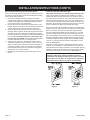
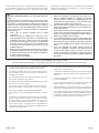
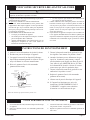
Figure 11
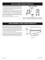
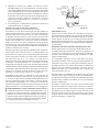
Electrode and pilot burner must be kept clean. Clean through
pilot access hole with a small brush (toothbrush) and water.
The pilot ame (Figure 11) going to the spark must be large enough
to completely cover the sparking area. With the proper ame, only
2 or 3 sparks will occur. More sparks indicate a small pilot ame
and no ignition with spark stopping after approximately 90 seconds
generally means not enough ame.
To adjust pilot ame remove the pilot cover screw on the control
valve (Figure 3, Page 9), and turn the adjustment screw clockwise
to reduce ame. Replace pilot cover screw to eliminate gas leakage.
The pilot ame will appear large. A blue nearly horizontal ame is
proper. The spark gap must be 1/8". A larger gap can result in the
spark occurring some other place. The pilot ame and the spark
gap are factory checked and tested.
After use, cleaning may be required for the proper ame.
The correct ame will be a short blue inner ame with a much
larger light blue outer ame. The main burner (Figure 12) shows
the approximate height of each part of the ame for each gas. The
burner does not have a primary air adjustment. The ame will be
correct if the factory-set pressure and orice opening are used. After
the furnace has been operating, the burner ports may be blocked
by foreign matter carried in by combustion air. Therefore, cleaning
of the burner may be needed for proper ame.
To clean burner port disconnect the gas supply to the valve, and
remove the eight screws fastening the burner door. After removing the
burner door from the combustion chamber, remove rear burner, pilot
burner and front burner. With front and rear burners removed from
furnace, force water into the ribbon ports and dry with air pressure.
Figure 12
PILOT FLAME CHARACTERISTICS
MAIN BURNER FLAME CHARACTERISTICS

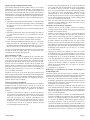
37403-5-0620 Page 15
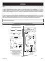
IF ANY OF THE ORIGINAL WIRE AS SUPPLIED
WITH THIS UNIT MUST BE REPLACED, IT MUST
BE REPLACED WITH 150°C THERMOPLASTIC
4/64 THICK OR ITS EQUIVALENT.
120V. 60Hz. LESS THAN 3 AMPS
S´IL YAUN FIL ORIGINAL FOURNI AVEC
L´APPAREIL QUI DIOT ÊTRE REMPLACÉ. IL DOIT
ÊTRE REMPLACÉ AVEC UN FIL
THERMOPLASTIQUE 150°C.
120V. 60Hz. MOINS DE 3 AMPS.
—————— ———————————————————————————————————————————————
WHITE (BLANC)
LOW VOLTAGE (BAS VOLTAGE)
120 VOLTS
120 VOLTS
SCHEMATIC WIRING DIAGRAM
——————————————————————————————
SCHÉMA ÉINSTALLATION LECTRIQUE
JUNCTION BOX
—— —— ——— —————————————— ——
BOÎTE DE JONCTION
LIMIT CONTROL
——— — ——————————————— —
CONTROL DE
TOLERANCE
AUTO FAN
——— —— ——————————— —
VENTILATE
AUTO
TRANSFORMER
——— —— —————————————————— —
TRANSFORMATEUR
SPT-3 CORDSET
——— —— ——————————————— —
CORDON SPT-3
BLACK (NOIR)
LADDER WIRING DIAGRAM
——————————————————————————
DIAGRAMME À L´ÉCHELLE
D´INSTALLATION ÉLECTRIQUE
YELLOW
——— —————————
JAUNE
WHITE
——— —————————
BLANC
BLACK
——— —————————
NOIR
RED
—
ROUGE
WHT
—
BLANC
TRANSFORMER
——— —— —————————————————— —
TRANSFORMATEUR
24 VOLTS
MOTOR
————— —————
MOTEUR
AUTO FAN
——— —— ——————————— —
VENTILATEUR
AUTO
MOTOR
————— —————
MOTEUR
BRN/Brun
WHT/Blanc
RED/Rouge
GRN/Vert
MV
MV/PV
PV
GRND
GAS VALVE
——— — ——————————————— —
VALVE DE GAZ
MODULE
LIMIT CONTROL
——— — ——————————————— —
CONTROL DE
TOLERANCE
GAS VALVE
——— — ——————————————— —
VALVE DE GAZ
BRN/Brun
MODULE
WHT/Blanc
RED/Rouge
GRN/Vert
MV
MV/PV
PV
MV
MV/PV
PV
GRND
24V
24V
R12352
ON/OFF DEVICE
——— — ——————————————— —
ON/OFF
PÉRIPHÉRIQUES
WIRE
NUT
————————————— —
FILS
TORSADÉS
WIRE NUT
—————————————---------------- —
FILS TORSADÉS
ON/OFF DEVICE
——— — ——————————————— —
ON/OFF
PÉRIPHÉRIQUES
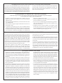
Wiring
The appliance, when installed, must be electrically grounded in accordance with local codes or, in the absence of local codes, with the
National Electrical Code, ANSI/NFPA 70 or Canadian Electrical Code, CSA C22.1, if an external electrical source is utilized. This appliance
is equipped with a three-prong [grounding] plug for your protection against shock hazard and should be plugged directly into
a properly grounded three-prong receptacle. Do not cut or remove the grounding prong from this plug. For an ungrounded
receptacle, an adapter, which has two prongs and a wire for grounding, can be purchased, plugged into the ungrounded receptacle and
its wire connected to the receptacle mounting screw. With this wire completing the ground, the appliance cord plug can be plugged into
the adapter and be electrically grounded. A 7/8" hole is provided in the junction box for use with a conduit connector if local codes require
this type of protection.
Installing the ON/OFF Device
To install an ON/OFF device (such as a wall switch, remote, toggle switch,or thermostat), remove the wire nut from the two wires from
the valve. Run additional wire from the valve wires to the ON/OFF device. Install the ON/OFF device in the same room as the furnace
following the installation instructions supplied with it. In the absence of instructions, install the ON/OFF device 4 to 5 feet above the oor
on an interior wall not affected by another heating source (i.e. stove or water heater) or the temperature of an adjoining room.
CAUTION: Label all wires prior to disconnection when servicing controls. Wiring errors can cause improper and dangerous operation.
Verify proper operation after servicing.
To Conserve Gas: Turn off pilot when heater is not in use.
Figure 13
WIRING

37403-5-0620Page 16
GENERAL: All furnaces have been re-tested to check for proper
operation. This includes, main burner ame, pilot ame, fan
operation, fan control, limit control and automatic valve operation.
If the furnace fails to function on initial installation, it is advisable to
re-check the following:
1. 115 volts to the junction box.
2. Inlet gas pressure.
3. The 24 volt system.
4. Type of gas being used and that shown on the rating label.
Servicing the Pilot and Main Burners, Pilot Orice, and Main
Burner Orices: Disconnect the gas supply at the inlet to the
control valve. Then remove the burner door to which the above
components are attached.
Servicing The Fan Motor: The upper front panel, the shroud
surrounding the fan blade and fan blade must be removed.
Replacing Fan and Oiling the Motor
The fan motor should be cleaned and oiled once each heating season.
To reach the motor, withdraw the metal shroud surrounding the fan
blade by removing the screws on each side. Oil holes are located
on the top at each end of the motor. Use a few drops of #10 motor
oil. To clean the motor, blow air through its ventilation openings
with a vacuum cleaner or low pressure air source.
If fan motor is replaced, the silicone rubber gaskets, see Page 20,
Index No. 4, Part No. M147, should also be replaced. The gaskets
must be stretched to t the motor bolts into the gasket holes and
then the motor and gaskets installed on the motor mounting bars.
S8600H INTERMITTENT IGNITION MODULE SPECIFICATIONS
Lockout timing is 90 seconds. Ignition timing is until pilot lights or
lockout occurs.
Module shuts down and cuts power to gas control on ame failure.
Gas control closes to provide 100 percent lockout on ame failure.
Manual reset required.
ELECTRICAL RATINGS:
Voltage and frequency: 20.5 to 28.5V (24V nom.) 60 Hz.
Current rating: 0.2 A.
Valve contact ratings (at 24 Vac):
Run Inrush
Pilot 1.0 A 10.0 A
Main 1.0 A 10.0 A
SPARK GENERATOR OUTPUT: 13kV peak at 25 pf load.
ANTICIPATOR SETTING: 0.2 A plus pilot valve rating plus main
valve rating.
COMPATIBILITY: Standard models compatible with all open-close
switch type 24 Vac capable of supplying rated voltage and current
to the module.
AMBIENT TEMPERATURE RATING: Minus 40 F to plus 175 F
(minus 40 C to plus 79 C).
RELATIVE HUMIDITY RATING: 5 to 90 percent RH at 95 F.
FLAME FAILURE RESPONSE TIME: 0.8 seconds at 1.0 uA ame
current.
FLAME CURRENT: 1 uA, min.
CHECKOUT
Check out the gas control system:
1. At initial installation of the appliance.
2. As part of regular maintenance procedures.
3. As the rst step in troubleshooting.
4. Any time work is done on the system.
STEP 1: Perform Visual Inspection.
A. With power off, make sure all wiring connections are clean and
tight.
B. Turn on power to appliance and ignition module.
C. Open manual shutoff valves in the gas line to the appliance.
D. Do gas leak test ahead of gas control if piping has been disturbed.
GAS LEAK TEST: Paint pipe joints with rich soap and water
solution. Bubbles indicate gas leak. Tighten joints to stop leak.
STEP 2: Review Normal Operating Sequence and Module
Specications.
STEP 3: Reset the Module.
A. Turn the control valve to off.
B. Wait one minute.
As you do Steps 4 and 5, watch for points where operation
deviates from normal. Refer to Troubleshooting Chart to correct
problem.
STEP 4: Check Safety Lockout Operation.
A. Turn gas supply off.
B. Watch for spark at pilot burner.
C. Time length of spark operation. Maximum spark time is 90
seconds.
D. Open manual gas cock and make sure no gas is owing to pilot
or main burner.
E. Wait one minute before continuing.
STEP 5: Check Normal Operation.
A. Turn contol valve on to call for heat.
B. Make sure pilot lights smoothly when gas reaches the pilot
burner.
C. Make sure main burner lights smoothly without ashback. Make
sure burner operates smoothly without oating or lifting.
D. If gas line has been disturbed, complete gas leak test.
GAS LEAK TEST: Paint gas control gasket edges and all pipe
connections downstream of gas control, including pilot tubing
connections, with rich soap and water solution. Bubbles indicate
gas leaks. Tighten joints and screws or replace component to
stop gas leak.
E. Turn control valve off. Make sure main burner and pilot ames
go out.
OPERATION
Module operation can be conveniently divided into two phases for
S8600H. The phases are trial for ignition and main burner operation.
SERVICE & MAINTENANCE SUGGESTIONS

37403-5-0620 Page 17
TRIAL FOR IGNITION
Pilot Ignition
Following call for heat (system start on S8600H), the module
energizes the rst main valve operator. The rst main valve opens,
which allows gas to ow to the pilot burner. At the same time, the
electronic spark generator in the module produces a 13,000 volt
spark pulse output (at 25 pf load). The voltage generates a spark
at the igniter-sensor that lights the pilot.
If the pilot does not light, or the pilot ame current is not at least 1.0
uA and steady, the module will not energize the second main valve
and the main burner will not light.
Safety Lockout
S8600H provides 100 percent shutoff, or safety lockout. A timer
starts timing the moment the trial for ignition starts. Ignition spark
continues only until the timed trial for ignition period ends. Then
the module goes into safety lockout. Lockout de-energizes the
rst main valve operator and closes the rst main valve in the gas
control, stopping pilot gas ow. The control system must be reset
by turning the valve off for one minute or by turning off power to the
module for one minute.
Main Burner Operation
When the pilot ame is established, a ame rectication circuit
is completed between the sensor and burner ground. The ame
sensing circuit in the module detects the ame current, shuts off
the spark generator and energizes the second main valve operator.
The second main valve opens and gas ows to the main burner,
where it is ignited by the pilot burner. The ame current also holds
the safety lockout timer in the reset (normal) operating condition.
When the call for heat ends, both main valve operators are de-
energized, and both main valves in the gas control close.
STAGE 1
TRIAL FOR IGNITION
IF FLAME CURRENT SENSED
*SPARK GENERATOR OFF
*SECOND VALVE OPERATOR (MAIN) OPENS
S8600H NORMAL OPERATING SEQUENCE
SERVICE & MAINTENANCE SUGGESTIONS (CONT'D)

37403-5-0620Page 18
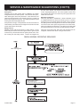
Important
1. The following service procedures are provided as a general
guide.
2. Meter readings between gas control and ignition module must
be taken within the trial for ignition period. Once the ignition
module locks out, the system must be reset by turning the valve
off for at least one minute before continuing.
3. If any component does not function properly, make sure it is
correctly installed and wired before replacing it.
4. The ignition module cannot be repaired. If it malfunctions, it
must be replaced.
5. Only trained, experienced service technicians should service
intermittent pilot systems.
Perform the CHECKOUT steps on page 15 as the rst step in
troubleshooting. Then check TROUBLESHOOTING GUIDE to
pinpoint the cause of the problem. If troubleshooting indicates an
ignition problem, see Ignition System Checks below to isolate and
correct the problem.
Following troubleshooting, perform the CHECKOUT procedure
(page 15) again to be sure system is operating normally.
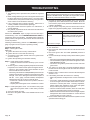
Ignition System Checks
Step 1: Check ignition cable.
Make sure:
A. Ignition cable does not touch any metal surfaces.
B. Ignition cable is no more than 36 inches long.
C. Connections to the ignition module and to the igniter-sensor
are clean and tight.
D. Ignition cable provides good electrical continuity.
Step 2: Check ignition system grounding.
Nuisance shutdowns are often caused by a poor or erratic
ground.
A. A common ground, usually supplied by the pilot burner bracket,
is required for the module and the pilot burner/igniter sensor.
• Check for good metal-to-metal contact between the pilot
burner bracket and the main burner.
• Check the ground lead from GND (BURNER) terminal on the
module to the pilot burner. Make sure connections are clean
and tight. If the wire is damaged or deteriorated, replace it
with No. 14-18 gauge, moisture-resistant, thermoplastic
insulated wire with 105 C (221 F) minimum rating.
• If ame rod or bracket are bent out of position, restore to
correct position.
• Replace pilot burner/igniter sensor if insulator is cracked.
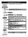
Step 3: Check spark ignition circuit. You will need a short jumper
wire made from ignition cable or other heavily insulated
wire.
A. Close the manual gas valve.
B. Disconnect the ignition cable at the SPARK terminal on the
module.
WARNING
When performing the following steps, do not touch stripped end of
jumper or SPARK terminal. The ignition circuit generates 13,000
volts at 25 pf load and electrical shock can result.
C. Energize the module and immediately touch one end of the
jumper rmly to the GND terminal on the module. Move the
free end of the jumper slowly toward the SPARK terminal until
a spark is established.
D. Pull the jumper slowly away from the terminal and note the
length of the gap when sparking stops. Check table below.
ARC LENGTH ACTION
No arc or arc less than
1/8 inch
Arc 1/8 inch or longer
Check external fuse, if provided.
Verify power at module input terminal.
Replace module if fuse and power
okay.
Voltage output is okay.
Step 4: Check pilot ame current.
A. Turn off furnace.
B. Disconnect main valve wire from the TH or MV terminal on the
gas control.
C. Disconnect ground wire from GND (BURNER) terminal at
module.
D. Connect a meter (dc microamp scale) in series with the ground
lead.
• Disconnect ground lead from GND terminal on ignition module.
• Connect the black (negative) meter lead to the ignition module
GND (BURNER) terminal.
• Connect the red (positive) meter lead to the free end of the
ground lead.
E. Turn valve on to call for heat. The spark will light the pilot but
the main burner will not light because the main valve actuator
is disconnected.
F. Read the meter. The ame sensor current must be steady and
at least 1.0 uA.
G. If the reading is less than the minimum or unsteady,
• Make sure pilot ame envelopes 3/8 to 1/2 inch of the ame
rod.
• If necessary, adjust pilot ame by turning the pilot adjustment
screw on the gas control clockwise to decrease or counter-
clockwise to increase pilot ame. Following adjustment,
always replace pilot adjustment cover screw and tighten
rmly to assure proper gas control operation.
• Check for cracked ceramic insulator, which can cause short
to ground, and replace igniter-sensor if necessary.
• Make sure electrical connections are clean and tight. Replace
damaged wire with moisture-resistant No. 18 wire rated for
continuous duty up to 105 C (221 F).
H. Remove meter and reconnect all wires. Return system to normal
operation before leaving job.
TROUBLESHOOTING

37403-5-0620 Page 19
TROUBLESHOOTING (CONT'D)

37403-5-0620Page 20
TROUBLESHOOTING (CONT'D)
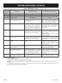
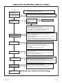
Green LED Status Codes
Green LED
Flash Code
(X + Y)
a
Indicates Next System Action Recommended Service Action
OFF No “Call for Heat” Not applicable None
Flash Fast Startup-Flame sense calibration Not applicable None
Heart Beat Normal operation Not applicable None
3
Recycle
- Flame failed during run
Initiate new trial for ignition. Flash code
will remain through the ignition trial until
ame is proved.
If system fails to light on next trial for
ignition, check gas supply, pilot burner,
ame sense wiring, contamination of
ame rod, burner ground connection.
4
Flame sensed out of sequence If situation self corrects within 10 sec-
onds, control returns to normal se-
quence. If ame out of sequence re-
mains longer than 10 seconds, control
goes to Flash code 6 + 4 (see below).
Check for pilot ame. Replace gas valve
if pilot ame present. If no pilot ame,
cycle “Call for Heat.” If error repeats, re-
place control.
7
Flame sense leakage to ground Control remains in wait mode. When the
fault corrects, control resumes normal
operation after a one minute delay.
Check ame sense lead wire for dam-
age or shorting. Check that ame rod is
in proper position.
Check ame rod ceramic for cracks,
damage or tracking.
8
Low secondary voltage supply -
below 15.5 Vac)
Control remains in wait mode. When the
fault corrects, control resumes normal
operation after a one minute delay.
Check transformer and AC line for prop-
er input voltage to the control. Check
with full system load on the transformer.
6 + 2
Failed trial for ignition resulting in
lockout
Remain in lockout until “Call for Heat” is
cycled.
Check gas supply, pilot burner, spark
and ame sense wiring, ame rod con-
taminated or out of position, burner
ground connection.
6 + 3
More than 5 ame failures during
run on the same “Call for Heat” re-
sulting in lockout
Remain in lockout until “Call for Heat” is
cycled.
Check gas supply, pilot burner, ame
sense wiring, contamination of ame
rod, burner ground connection.
6 + 4
Flame sensed out of sequence -
longer than 10 seconds
Control waits until ame is no longer
sensed and then goes to soft lockout.
Flash code continues. Control auto re-
sets from soft lockout after one hour.
Check for pilot ame. Replace gas valve
if pilot ame present. If no pilot ame,
cycle “Call for Heat.” If error repeats, re-
place control.
ON
Soft lockout due to error detected
during self check sequences
Control auto resets from soft lockout af-
ter one hour.
Reset by cycling “Call for Heat.” If error
repeats, replace the control.
a
Flash Code Descriptions:
- Flash Fast: Rapid blinking
- Heartbeat: Constant 1/2 second bright 1/2 second dim cycles
- A single ash code number signies that the LED ashes X times at 2Hz, remains off for two seconds, and then repeats the
sequence.
- X + Y ash codes signify that the LED ashes X times at 2Hz, remains off for two seconds, ashes Y times at 2Hz, remains off
for three seconds, and then repeats the sequence.
La page charge ...
La page charge ...
La page charge ...
La page charge ...
La page charge ...
La page charge ...
La page charge ...
La page charge ...
La page charge ...
La page charge ...
La page charge ...
La page charge ...
La page charge ...
La page charge ...
La page charge ...
La page charge ...
La page charge ...
La page charge ...
La page charge ...
La page charge ...
La page charge ...
La page charge ...
La page charge ...
La page charge ...
-
 1
1
-
 2
2
-
 3
3
-
 4
4
-
 5
5
-
 6
6
-
 7
7
-
 8
8
-
 9
9
-
 10
10
-
 11
11
-
 12
12
-
 13
13
-
 14
14
-
 15
15
-
 16
16
-
 17
17
-
 18
18
-
 19
19
-
 20
20
-
 21
21
-
 22
22
-
 23
23
-
 24
24
-
 25
25
-
 26
26
-
 27
27
-
 28
28
-
 29
29
-
 30
30
-
 31
31
-
 32
32
-
 33
33
-
 34
34
-
 35
35
-
 36
36
-
 37
37
-
 38
38
-
 39
39
-
 40
40
-
 41
41
-
 42
42
-
 43
43
-
 44
44


Empire Heating Systems DVC55 Le manuel du propriétaire
- Taper
- Le manuel du propriétaire
- Ce manuel convient également à
dans d''autres langues
Documents connexes
-
Empire Heating Systems DV-35-2SG Le manuel du propriétaire
-
Empire Heating Systems Direct-Vent Wall Counterflow Le manuel du propriétaire
-
-
Empire Heating Systems Direct-Vent Wall Furnace (DV210/215) Le manuel du propriétaire
-
-
-
-
Empire Heating Systems DV-40E-5 Le manuel du propriétaire
-
-
Autres documents
-
Empire DV-55-1SPP Installation Instructions And Owner's Manual
-
-
Empire Comfort Systems MV 145 Manuel utilisateur
-
-
Empire DVC-35-2IP Le manuel du propriétaire
-
-
American Hearth DV-822 Le manuel du propriétaire
-
Camco 25252 Guide d'installation
-
-
Behringer HA400 Microamp Le manuel du propriétaire