Yamaha CRX-E320 Le manuel du propriétaire
- Catégorie
- Lecteur CD
- Taper
- Le manuel du propriétaire

YAMAHA ELECTRONICS CORPORATION, USA
6660 ORANGETHORPE AVE., BUENA PARK, CALIF. 90620, U.S.A.
YAMAHA CANADA MUSIC LTD.
135 MILNER AVE., SCARBOROUGH, ONTARIO M1S 3R1, CANADA
YAMAHA ELECTRONIK EUROPA G.m.b.H.
SIEMENSSTR. 22-34, 25462 RELLINGEN BEI HAMBURG, GERMANY
YAMAHA ELECTRONIQUE FRANCE S.A.
RUE AMBROISE CROIZAT BP70 CROISSY-BEAUBOURG 77312 MARNE-LA-VALLEE CEDEX02, FRANCE
YAMAHA ELECTRONICS (UK) LTD.
YAMAHA HOUSE, 200 RICKMANSWORTH ROAD WATFORD, HERTS WD18 7GQ, ENGLAND
YAMAHA SCANDINAVIA A.B.
J A WETTERGRENS GATA 1, BOX 30053, 400 43 VÄSTRA FRÖLUNDA, SWEDEN
YAMAHA MUSIC AUSTRALIA PTY, LTD.
17-33 MARKET ST., SOUTH MELBOURNE, 3205 VIC., AUSTRALIA
©
2007 All rights reserved.
OWNER'S MANUAL
MODE D'EMPLOI
AMPLI-TUNER CD
CD RECEIVER
UCA
Printed in China CQX1A1201Z
CRX-E320_UCA_cv.fm Page 1 Thursday, June 21, 2007 3:51 PM

i En
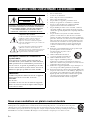
• Explanation of Graphical Symbols
The lightning flash with arrowhead symbol, within an
equilateral triangle, is intended to alert you to the
presence of uninsulated “dangerous voltage” within
the product’s enclosure that may be of sufficient
magnitude to constitute a risk of electric shock to
persons.
The exclamation point within an equilateral triangle
is intended to alert you to the presence of important
operating and maintenance (servicing) instructions in
the literature accompanying the appliance.
1 Read these instructions.
2 Keep these instructions.
3 Heed all warnings.
4 Follow all instructions.
5 Do not use this apparatus near water.
6 Clean only with dry cloth.
7 Do not block any ventilation openings. Install in accordance
with the manufacturer’s instructions.
8 Do not install near any heat sources such as radiators, heat
registers, stoves, or other apparatus (including amplifiers)
that produce heat.
9 Do not defeat the safety purpose of the polarized or
grounding-type plug. A polarized plug has two blades with
one wider than the other. A grounding type plug has two
blades and a third grounding prong. The wide blade or the
third prong are provided for your safety. If the provided plug
does not fit into your outlet, consult an electrician for
replacement of the obsolete outlet.
10 Protect the power cord from being walked on or pinched
particularly at plugs, convenience receptacles, and the point
where they exit from the apparatus.
11 Only use attachments/accessories specified by the
manufacturer.
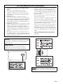
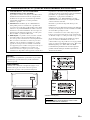
12 Use only with the cart, stand, tripod,
bracket, or table specified by the
manufacturer, or sold with the apparatus.
When a cart is used, use caution when
moving the cart/apparatus combination
to avoid injury from tip-over.
13 Unplug this apparatus during lightning storms or when
unused for long periods of time.
14 Refer all servicing to qualified service personnel. Servicing
is required when the apparatus has been damaged in any
way, such as power-supply cord or plug is damaged, liquid
has been spilled or objects have fallen into the apparatus, the
apparatus has been exposed to rain or moisture, does not
operate normally, or has been dropped.
IMPORTANT SAFETY INSTRUCTIONS
Note to CATV system installer:
This reminder is provided to call the CATV system
installer’s attention to Article 820-40 of the NEC that
provides guidelines for proper grounding and, in
particular, specifies that the cable ground shall be
connected to the grounding system of the building, as
close to the point of cable entry as practical.
IMPORTANT
Please record the serial number of this unit in the space
below.
MODEL:
Serial No.:
The serial number is located on the rear of the unit.
Retain this Owner’s Manual in a safe place for future
reference.
CAUTION
RISK OF ELECTRIC SHOCK
DO NOT OPEN
CAUTION: TO REDUCE THE RISK OF
ELECTRIC SHOCK, DO NOT REMOVE
COVER (OR BACK). NO USER-SERVICEABLE
PARTS INSIDE. REFER SERVICING TO
QUALIFIED SERVICE PERSONNEL.
We Want You Listening For A Lifetime
Yamaha and the Electronic Industries Association’s Consumer Electronics Group want you to get the most out of your
equipment by playing it at a safe level. One that lets the sound come through loud and clear without annoying blaring or
distortion – and, most importantly, without affecting your sensitive hearing. Since hearing damage from loud sounds is
often undetectable until it is too late, Yamaha and the Electronic Industries Association’s Consumer Electronics Group
recommend you to avoid prolonged exposure from excessive volume levels.

ii En
Compliance with FCC regulations does not guarantee that
interference will not occur in all installations. If this
product is found to be the source of interference, which
can be determined by turning the unit “OFF” and “ON”,
please try to eliminate the problem by using one of the
following measures:
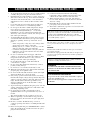
Relocate either this product or the device that is being
affected by the interference.
Utilize power outlets that are on different branch (circuit
breaker or fuse) circuits or install AC line filter/s.
In the case of radio or TV interference, relocate/reorient
the antenna. If the antenna lead-in is 300 ohm ribbon lead,
change the lead-in to coaxial type cable.
If these corrective measures do not produce satisfactory
results, please contact the local retailer authorized to
distribute this type of product. If you can not locate the
appropriate retailer, please contact Yamaha Electronics
Corp., U.S.A. 6660 Orangethorpe Ave, Buena Park, CA
90620.
The above statements apply ONLY to those products
distributed by Yamaha Corporation of America or its
subsidiaries.
1 IMPORTANT NOTICE: DO NOT MODIFY THIS
UNIT!
This product, when installed as indicated in the
instructions contained in this manual, meets FCC
requirements. Modifications not expressly approved by
Yamaha may void your authority, granted by the FCC, to
use the product.
2 IMPORTANT: When connecting this product to
accessories and/or another product use only high quality
shielded cables. Cable/s supplied with this product MUST
be used. Follow all installation instructions. Failure to
follow instructions could void your FCC authorization to
use this product in the USA.
3 NOTE: This product has been tested and found to comply
with the requirements listed in FCC Regulations, Part 15
for Class “B” digital devices. Compliance with these
requirements provides a reasonable level of assurance that
your use of this product in a residential environment will
not result in harmful interference with other electronic
devices.
This equipment generates/uses radio frequencies and, if
not installed and used according to the instructions found
in the users manual, may cause interference harmful to the
operation of other electronic devices.
FCC INFORMATION (for US customers)
CAUTION
Use of controls or adjustments or performance of procedures
other than those specified herein may result in hazardous
radiation exposure.
AVERTISSEMENT
L’utilisation de commandes et l’emploi de réglages ou de
méthodes autres que ceux décrits ci-dessous, peuvent
entraîner une exposition à un rayonnement dangereux.
CLASS 1 LASER PRODUCT
LASER KLASSE 1 PRODUKT
LUOKAN 1 LASERLAITE
KLASS 1 LASER APPARAT
PRODUIT LASER DE CLASSE 1
CAUTION INVISIBLE LASER RADIATION WHEN OPEN
AND INTERLOCKS DEFEATED. AVOID EXPOSURE TO
BEAM.

iii En
1 To assure the finest performance, please read this manual
carefully. Keep it in a safe place for future reference.
2 Install this unit in a well ventilated, cool, dry, clean place
with at least 10 cm on the top, 10 cm on the left and right,
and 10 cm at the back of this unit
— away from direct
sunlight, heat sources, vibration, dust, moisture, and/or
cold.
3 Locate this unit away from other electrical appliances,
motors, or transformers to avoid humming sounds.
4 Do not expose this unit to sudden temperature changes
from cold to hot, and do not locate this unit in an
environment with high humidity (i.e. a room with a
humidifier) to prevent condensation inside this unit,
which may cause an electrical shock, fire, damage to this
unit, and/or personal injury.
5 Avoid installing this unit where foreign object may fall
onto this unit and/or this unit may be exposed to liquid
dripping or splashing. On the top of this unit, do not
place:
– Other components, as they may cause damage and/or
discoloration on the surface of this unit.
– Burning objects (i.e. candles), as they may cause fire,
damage to this unit, and/or personal injury.
– Containers with liquid in them, as they may fall and
liquid may cause electrical shock to the user and/or
damage to this unit.
6 Do not cover this unit with a newspaper, tablecloth,
curtain, etc. in order not to obstruct heat radiation. If the
temperature inside this unit rises, it may cause fire,
damage to this unit, and/or personal injury.
7 Do not plug in this unit to a wall outlet until all
connections are complete.
8 Do not operate this unit upside-down. It may overheat,
possibly causing damage.
9 Do not use force on switches, knobs and/or cords.
10 When disconnecting the power cable from the wall outlet,
grasp the plug; do not pull the cable.
11 Do not clean this unit with chemical solvents; this might
damage the finish. Use a clean, dry cloth.
12 Only voltage specified on this unit must be used. Using
this unit with a higher voltage than specified is dangerous
and may cause fire, damage to this unit, and/or personal
injury. Yamaha will not be held responsible for any
damage resulting from use of this unit with a voltage
other than specified.
13 To prevent damage by lightning, keep the power cord and
outdoor antennas disconnected from a wall outlet or this
unit during a lightning storm.
14 Do not attempt to modify or fix this unit. Contact
qualified Yamaha service personnel when any service is
needed.
The cabinet should never be opened for any reasons.
15 When not planning to use this unit for long periods of
time (i.e. vacation), disconnect the AC power plug from
the wall outlet.
16 Be sure to read the “Troubleshooting” section on
common operating errors before concluding that this unit
is faulty.
17 Before moving this unit, press STANDBY/ON to set this
unit to the standby mode, and disconnect the AC power
plug from the wall outlet.
18 Condensation will form when the surrounding
temperature changes suddenly. Disconnect the power
cable from the outlet, then leave this unit alone.
19 When using this unit for a long time, this unit may
become warm. Turn the power off, then leave this unit
alone for cooling.
20 Install this unit near the AC outlet and where the AC
power plug can be reached easily.
21 The batteries shall not be exposed to excessive heat such
as sunshine, fire or the like.
LASER SAFETY
This unit employs a laser. Due to possible eye injury, only a qualified
service person should remove the cover or attempt to service this
device.
DANGER
This unit emits visible laser radiation when open. Avoid direct
eye exposure to beam.
When this unit is plugged into the wall outlet, do not place your
eyes close to the opening of the disc tray and other openings to
look into inside.
CAUTION: READ THIS BEFORE OPERATING YOUR UNIT.
This unit is not disconnected from the AC power source as
long as it is connected to the wall outlet, even if this unit itself
is turned off by STANDBY/ON. This state is called the
standby mode. In this state, this unit is designed to consume a
very small quantity of power.
The laser component in this product is capable of emitting
radiation exceeding the limit for Class 1.
WARNING
TO REDUCE THE RISK OF FIRE OR ELECTRIC
SHOCK, DO NOT EXPOSE THIS UNIT TO RAIN
OR MOISTURE.
FOR CANADIAN CUSTOMERS
To prevent electric shock, match wide blade of plug to
wide slot and fully insert.
This Class B digital apparatus complies with Canadian
ICES-003.

1 En
English
PREPARATIONINTRODUCTION
BASIC
OPERATION
ADVANCED
OPERATION
ADDITIONAL
INFORMATION
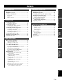
Features ................................................................... 2
Supplied accessories ............................................... 2
Controls and functions........................................... 3
Front panel ................................................................. 3
Display....................................................................... 4
Remote control........................................................... 5
Connecting speakers............................................... 9
Connecting a subwoofer .......................................... 10
Connecting antennas ............................................ 11
Connecting the AM loop antenna ............................ 11
Connecting the FM antenna..................................... 11
Connecting external components ........................ 12
Connecting a CD or MD recorder ........................... 12
Connecting a USB device........................................ 13
Connecting a portable audio device......................... 13
Connecting headphones........................................... 13
Connecting the power cable................................. 14
Turning on and off the power.............................. 14
Adjusting the clock ............................................... 15
Basic receiver operation....................................... 16
Selecting the input source........................................ 16
Adjusting the volume level...................................... 16
Basic playback operations
for discs and USB devices ................................ 17
Switching the playback information display ........... 19
Repeat playback (REPEAT) .................................... 21
Random playback (RANDOM)............................... 21
Programmed playback (PROGRAM)...................... 22
Index Search (Audio CD only)................................ 23
FM/AM tuning ...................................................... 24
Tuning radio stations automatically
(Auto tuning) ....................................................... 24
Tuning radio stations manually
(Manual tuning)................................................... 24
Presetting radio stations automatically
(Auto preset)........................................................ 25
Presetting radio stations manually
(Manual preset).................................................... 25
Selecting preset radio stations
(Preset tuning) ..................................................... 26
Editing the name of preset radio stations................. 26
Receiving Radio Data System stations
(U.K. and Europe models only)........................... 27
Setting the timer ....................................................29
Setting the sleep timer...........................................30
Changing the front panel display settings...........31
Playing back external sources..............................32
Portable audio device playback ............................... 32
Other component playback ...................................... 32
Recording audio sources
with external components.................................33
Adjusting sounds...................................................34
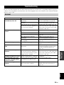
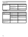
Troubleshooting.....................................................35
General..................................................................... 35
Remote control ........................................................ 36
Disc playback .......................................................... 36
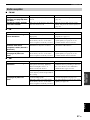
Radio reception........................................................ 37
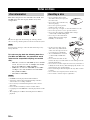
Notes on discs.........................................................38
Disc information ...................................................... 38
Handling a disc ........................................................ 38
Glossary..................................................................39
Specifications .........................................................39
Contents
INTRODUCTION
PREPARATION
BASIC OPERATION
ADVANCED OPERATION
ADDITIONAL INFORMATION

FEATURES
2 En
• Audio CDs, MP3 CDs, and WMA CDs playable
• USB supported
• Easy operation with MULTI JOG button
• Multi-function remote control
• DIGITAL OPTICAL OUT jack
■ About this manual
• In this manual, operations that can be performed with either this unit or its remote control are explained using the remote control.
• Remote control descriptions and illustrations in this manual are based on the U.K. and Europe models unless otherwise specified.
• y indicates a tip for your operation.
• Notes contain important information about safety and operating instructions.
• This manual is printed prior to production. Design and specifications are subject to change in part as a result of improvements, etc.
In case of differences between the manual and the product, the product has priority.
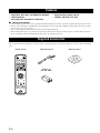
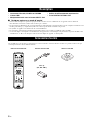
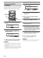
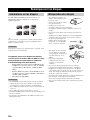
This product includes the following accessories. Before connecting speakers to this product, make sure you have all of the following
parts.
Features
Supplied accessories
STANDBY/ON
1 2 3 4
56
9
0
78
DIMMERINDEX
PTY SEEK
MODE START
RANDOM
ENTER
CD
BAND
PORTABLE
AUX
USB
PRESET VOLUME
OPEN/CLOSE
PROG
REPEAT
FREQ/TEXT
A B
TIME/INFO
DISPLAY
SLEEP
FOLDER
FILE
FILE
TUNER
MUTE
Indoor FM antenna AM loop antenna
Batteries (2)
(AA, R06, UM-3)
Remote control

3 En
English
INTRODUCTION
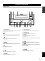
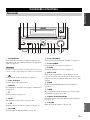
1 STANDBY/ON
Turns on this unit. Press this button again to set this unit to
the standby mode (see page 14).
In the standby mode, this unit consumes a small amount of power
in order to receive infrared signals from the remote control.
2
Opens and closes the disc tray (see page 17).
3 Disc tray
Holds a disc to be played.
4 Display
Displays playback information or settings (see page 4).
5 s
Stops playback (see page 17).
6 INPUT
Selects an input source (see page 16).
7 h/e
Starts and pauses playback (see page 17).
8 USB port
Connects your USB device (see page 13).
9 PORTABLE jack
Connects your portable audio device (see page 13).
0 PHONES jack
Connects your headphones (see page 13).
A SOUND
Switches the sound settings (see page 34).
B MULTI JOG
Adjusts various settings and the frequency when tuning
radio station. You can also skip tracks when CD or USB is
selected as the input source.
C MODE
Supports MULTI JOG and enables various operations.
D TIMER
Sets this unit to the timer play mode or sleep mode (see
pages 29 and 30).
E Remote control sensor
Receives signals from the remote control (see page 8).
F VOLUME
Adjusts volume level (see page 16).
Controls and functions
Front panel
STANDBY/ON
PHONESPORTABLE
USB SOUND MODE
VOLUME
INPUT
PUSH-ENTER
MULTI JOG
TIMER
4
1
23 675
890A CD FEB
Note

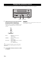
4 En
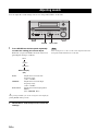
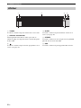
Controls and functions
1 TUNED
Lights up when this unit is tuned in to a station.
2 Multi-information display
Displays various information such as a title, track number,
and elapsed playing time for disc/USB playback.
3
Lights up when the timer play function is activated (see
page 29).
4 SLEEP
Lights up when the sleep timer function is activated (see
page 30).
5 STEREO
Lights up when receiving a strong FM radio signal in the
FM stereo mode.
6 USB
Lights up while a USB device is inserted.
Display
USB
SLEEP
TUNED
STEREO
65
1342

5 En
Controls and functions
English
INTRODUCTION
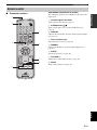
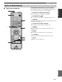
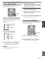
■ Common functions
Operations common to all modes
The following operations are available for this unit in any
input mode.
1 Infrared signal transmitter
Sends signals to this unit (see page 8).
2 STANDBY/ON ( )
Turns on this unit or sets it to the standby mode (see
page 14).
3 DISPLAY
Switches the information shown in the front panel display
(see page 31).
4 Input selection keys
Select the input source (see page 16).
5 DIMMER
Changes the brightness of the front panel display (see
page 31).
6 SLEEP
Sets the sleep timer (see page 30).
7 VOLUME +/–
Adjusts the overall volume level (see page 16).
8 MUTE
Turns off the volume (see page 16).
Remote control
STANDBY/ON
1 2 3 4
56
9
0
78
DIMMERINDEX
PTY SEEK
MODE START
RANDOM
ENTER
CD
BAND
PORTABLE
AUX
USB
PRESET
VOLUME
OPEN/CLOSE
PROG
REPEAT
FREQ/TEXT
A B
TIME/INFO
FOLDER
FILE FILE
TUNER
MUTE
DISPLAY
SLEEP
1
4
7
6
2
3
5
8

6 En
Controls and functions
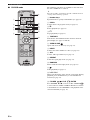
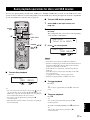
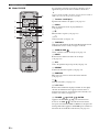
■ CD/USB mode
The following operations are available for this unit when
the CD or USB mode is selected.
y
Press CD or USB to set this unit to the CD or USB mode before
carrying out the following operations.
1 Number keys
Input numerals to specify track numbers (see page 18).
2 PROG
Sets this unit to the program mode (see page 22).
3 e
Pauses playback (see page 17).
4 s
Stops playback (see page 17).
5 TIME/INFO
Switches the disc/USB information shown in the front
panel display (see pages 19 and 20).
6 OPEN/CLOSE
Opens and closes the disc tray (see page 17).
7 INDEX
Searches the index numbers in a disc (see page 23).
8 A-B
Sets the A-B repeat function (see page 21).
9 REPEAT
Selects the repeat play mode (see page 21).
0 RANDOM
Turns on/off the random play mode (see page 21).
A h
Starts playback (see page 17).
B b / a
Skips to the beginning of the current or next track. During
playback, press and hold the key to search backward/
forward (see page 18).
C FOLDER , FILE , ENTER
Press FOLDER to select a folder and FILE
to select a file for an MP3 or WMA folder/file recorded on
a disc/USB device. Press ENTER to start playback of the
selected folder/file (see page 18).
STANDBY/ON
1 2 3 4
5 6
90
7 8
PTY SEEK
MODE START
RANDOM
ENTER
CD
BAND
PORTABLE
AUX
USB
PRESET VOLUME
OPEN/CLOSE
PROG
REPEAT
FREQ/TEXT
A B
TIME/INFO
SLEEP
FOLDER
FILE
FILE
TUNER
MUTE
DISPLAY
INDEX DIMMER
8
7
9
0
C
2
3
4
5
1
A
B
6
/
/
/
/

7 En
Controls and functions
English
INTRODUCTION
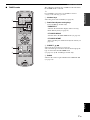
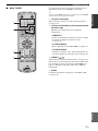
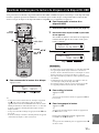
■ TUNER mode
The following operations are available for this unit when
the TUNER mode is selected.
y
Press TUNER to set this unit to the TUNER mode before
carrying out the following operations.
1 Number keys
Select the preset station number (see page 26).
2 Radio Data System tuning keys
(U.K. and Europe models only)
FREQ/TEXT
Switches the information display when receiving
Radio Data System (see page 28).
PTY SEEK MODE
Sets this unit to the PTY SEEK mode (see page 27).
PTY SEEK START
Starts searching for a Radio Data System station (see
page 28).
3 PRESET
Selects the preset stations (see page 26).
Also selects the preset stations once the desired program
type is selected in the PTY SEEK mode
(see page 27). (U.K. and Europe models only)
4 BAND
Switches the radio reception band between FM and AM
(see page 16).
STANDBY/ON
1 2 3 4
5 6
90
7 8
DIMMERINDEX
PTY SEEK
MODE START
RANDOM
ENTER
CD
BAND
PORTABLE
AUX
USB
PRESET VOLUME
OPEN/CLOSE
PROG
REPEAT
FREQ/TEXT
A B
TIME/INFO
SLEEP
FOLDER
FILE
FILE
TUNER
MUTE
DISPLAY
1
2
3
4
/

8 En
Controls and functions
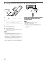
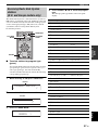
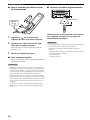
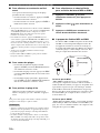
■ Installing batteries in the remote control
1 Press on the battery cover and open the
cover.
2 Insert the two supplied batteries (AA, R06,
UM-3) into the battery compartment.
Insert the batteries according to the polarity markings
(+ and –).
3 Close the battery cover.
■ To replace batteries
Change both batteries when the operation range of
the remote control decreases.
• Do not use an old battery together with a new one.
• Do not use different types of batteries (for example, alkaline
and manganese) together. Each type of battery has its own
characteristics even if they are similar in shape.
• If the batteries run out, immediately remove them from the
remote control to prevent an explosion or acid leak.
• If a battery starts leaking, dispose of it immediately. Be careful
not to let the leaking battery acid touch your skin or clothing.
• Before inserting new batteries, wipe the compartment clean.
• Dispose of batteries according to your regional regulations.
■ Using the remote control
Use the remote control within 6 m (20 feet) of this
unit and point it toward the remote control
sensor (see page 3).
• Do not spill liquid on the remote control.
• Do not drop the remote control.
• Do not leave the remote control in the following places:
– hot or humid places such as bathroom or near a heater
– extremely cold places
– dusty places
Notes
Press
Notes
30˚ 30˚
Within 6 m
(20 feet)

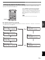
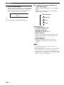
CONNECTING SPEAKERS
9 En
English
PREPARATION
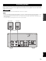
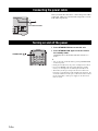
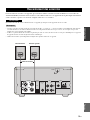
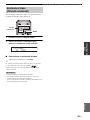
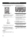
Follow the procedure below to connect your speakers to this unit. The connection example below uses the Yamaha NX-
E700 (consisting of two speakers) and its supplied cables. For information on your speakers, refer to the owner’s manual
supplied with your speakers.
Do not connect the power cable of this unit until all cable connections are completed.
• Be sure to connect the left channel (L), right channel (R), “+” (red) and “–” (black) properly. If the connections are faulty, no sound is
heard from the speakers. If the polarity of the speaker connections is incorrect, the sound can be unnatural and lacks bass.
• Do not let the bare speaker wires touch each other or do not let them touch any metal part of this unit. This could damage this unit
and/or your speakers.
• Use speakers with the specified impedance shown on the rear panel of this unit.
Connecting speakers
CAUTION
Notes
L
L
MAINS
DIGITAL
OPTICAL
TUNER
GND
AM
ANT
FM ANT
75Ω UNBAL.
OUT
SUB WOOFER
OUT
AUX
OUT
IN
R
R
SPEAKERS
Left speakerRight speaker
Speaker cables

Connecting speakers
10 En
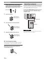
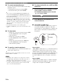
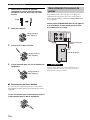
1 Remove approximately 10 mm (3/8 in) of
insulation from the end of each speaker
cable and then twist the exposed wires of the
cable together to prevent short circuits.
2 Unscrew the knob.
3 Insert the bare wire into the terminal.
4 Tighten the knob to secure the wire.
■ Connecting banana plugs
If you remove the caps from the terminals, you can also
use banana plugs to connect your speakers to this unit.
Tighten the each terminal knob, and insert the
banana plug connector into the end of the
corresponding terminal.
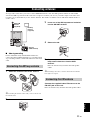
Connecting a subwoofer is optional. The low frequency
signals of the front left and right channels are downmixed
at the SUBWOOFER OUT jack of this unit.
Connect the SUBWOOFER OUT jack on this unit
to the INPUT jack on your subwoofer using a
subwoofer cable.
Do not connect the power cables of this unit and the subwoofer
until all cable connections are completed.
10 mm (3/8 in)
Red: positive (+)
Black: negative (–)
Red: positive (+)
Black: negative (–)
Red: positive (+)
Black: negative (–)
Connecting a subwoofer
CAUTION
L
DIGITAL
OPTICAL
OUT
SUB WOOFER
OUT
R
SPEAKERS
INPUT
INPUT
Subwoofer
Subwoofer cable

CONNECTING ANTENNAS
11 En
English
PREPARATION
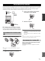
To enjoy radio on this unit, you need to connect FM/AM antennas to this unit. This product includes an indoor FM
antenna and AM loop antenna. If the radio wave reception is weak in your area or you want to improve the radio wave
reception, we recommend that you use outdoor antennas. For details, consult the nearest authorized Yamaha dealer or
service center.
■ About grounding
For the maximum safety and minimum interference,
connect the antenna GND terminal to a good earth ground.
A good earth ground is a metal stake driven into the moist
earth.
1 Attach the antenna stand to the antenna.
y
When attaching the antenna on the wall, you do not need to use
the antenna stand.
2 Press and hold the tab.
3 Insert one of the AM loop antenna lead wires
into the AM ANT terminal.
4 Release the tab.
5 Repeat steps 2 to 4 to insert the other AM
loop antenna lead wires into the GND
terminal.
Place the antenna away from this unit and speaker
cables.
y
While listening to the radio, rotate the antenna head to find the
best angle for reception.
Connect the supplied indoor FM antenna to the
FM ANT jack on this unit.
Place the antenna away from this unit and speaker cables.
Connecting antennas
Connecting the AM loop antenna
L
MAINS
TUNER
GND
AM
ANT
FM ANT
75Ω UNBAL.
U
T
R
Indoor FM
antenna
(supplied)
AM loop
antenna
(supplied)
Ground
(GND terminal)
Connecting the FM antenna

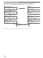
CONNECTING EXTERNAL COMPONENTS
12 En
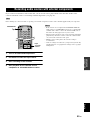
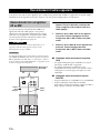
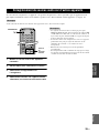
You can connect external components such as a CD or MD recorder to this unit. For information on your component,
refer to the owner’s manual supplied with the component.
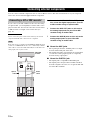
If you connect your CD or MD recorder to this unit using
an optical cable, you can digitally record the audio source
played on this unit. You can also select the connected CD
or MD recorder as an input source for this unit (see
page 32).
Do not connect the power cables of this unit and your external
component until all cable connections are completed.
Radio stations are not output from the DIGITAL OPTICAL OUT
jack. To record FM/AM broadcasts, use a commercially available
audio cable to connect the AUX OUT L/R jack on this unit to the
analog input jack on your recorder.
• Connect the DIGITAL OPTICAL OUT jack on
this unit to the digital input jack on your CD
or MD recorder using an optical cable.
• Connect the AUX OUT jacks on this unit to
the analog input jacks on your CD or MD
recorder using an audio cable.
• Connect the AUX IN jacks on this unit to the
analog output jacks on your CD or MD
recorder using an audio cable.
■ About the AUX jacks
• The signal input from the AUX IN jack is not output
from the AUX OUT jack on this unit.
• The digital and analog signal circuits are independent
of each other. Analog input signals are output only
from the analog output jacks.
■ About the DIGITAL jack
• The digital jack is compatible with PCM signal.
• The digital jack is designed based on EIA standards.
To make a digital connection, use an optical cable that
meets the EIA standards.
Connecting external components
Connecting a CD or MD recorder
CAUTION
Note
L
MAINS
DIGITAL
OPTICAL
F
M
7
5
OUT
SUB WOOFER
OUT
AUX
OUT
IN
R
L
R
ANALOG
DIGITAL
OPTICAL
IN OUT IN
CD or MD
recorder
Optical
cable
Audio
cables

Connecting external components
13 En
English
PREPARATION
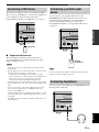
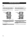
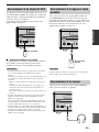
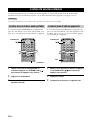
This unit has a USB port and can access MP3 or WMA
files saved on your USB device. Connect your USB device
to the USB port on the front panel of this unit.
For playback information of a USB device, see page 17.
■ Supported USB devices
This unit supports USB mass storage class devices
(e.g., flash memories or portable audio players) using
FAT16 or FAT32 format.
• Some devices may not work properly even if they meet the
requirements.
• If your USB device is not played back after you connected it to
this unit, follow any of the procedures below.
– Set this unit to the standby mode, and turn it on again.
– Disconnect the device while this unit is in the standby mode.
Then connect the device again and turn on this unit.
– Connect an AC adapter if supplied with the device.
• If the USB device is not played back even after you performed
the procedure(s) above, the device may not be playable on this
unit.
• Do not connect devices other than USB mass storage class
devices (such as USB chargers or USB hubs), PCs, card
readers, external HDD, etc.
• Yamaha will not be held responsible for any damage to or data
loss on the USB device occurring while the device is connected
to this unit.
• Playability of and power supply to all kind of USB devices are
not guaranteed.
You can connect your portable audio device to the
PORTABLE jack on the front panel of this unit. Use a
commercial audio cable with a 3.5 mm mini plug to
connect your portable audio device to this unit.
For playback information of your portable audio device,
see page 32.
Be sure to turn down the volume of this unit and your portable
audio device before making connection.
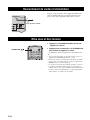
You can connect your headphones to the PHONES jack on
the front panel of this unit.
Connecting a USB device
Notes
STANDBY/ON
PHONESPORTABLE
SOUNDUSB
USB device
Connecting a portable audio
device
Note
Connecting headphones
STANDBY/ON
PHONES
SOUNDUSB
PORTABLE
Portable
audio device
STANDBY/ON
SOUNDUSB
PORTABLE PHONES

CONNECTING THE POWER CABLE
14 En
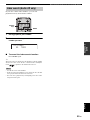
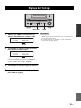
After you made all connections, connect the power cables
of this unit, subwoofer, and external component to an AC
wall outlet respectively.
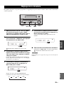
• Press STANDBY/ON to turn on this unit.
• Press STANDBY/ON again to set this unit to
the standby mode.
All display turns off and this unit turns into the eco
mode.
y
• You can also turn on/off this unit by pressing STANDBY/ON
on the front panel.
• During the standby mode, the power consumption is reduced.
• If you press MODE on the front panel during the standby
mode, you can display the clock during the standby mode.
• The memory back-up circuit prevents the stored data from
being lost even if this unit is in the standby mode. However, the
stored data will be lost if the power cable is disconnected from
the AC wall outlet or if the power supply is cut off for more
than one week.
Connecting the power cable
MAINS
TUNER
GND
AM
ANT
FM ANT
75Ω UNBAL.
OUT
AUX
L
R
To an AC wall outlet
Turning on and off the power
STANDBY/ON
1 2 3 4
56
9
0
78
DIMMERINDEX
PTY SEEK
OPEN/CLOSE
PROG
REPEAT
FREQ/TEXT
A B
STANDBY/ON ( )

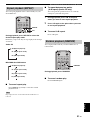
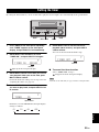
ADJUSTING THE CLOCK
15 En
English
PREPARATION
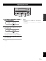
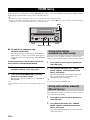
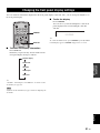
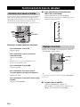
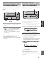
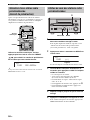
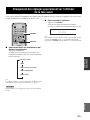
1 Press TIMER on the front panel, and push
MULTI JOG immediately.
2 Rotate MULTI JOG to adjust the hour, and
push MULTI JOG.
Time appears in 12-hour notation (AM/PM)
depending on the model. For example, “PM04:00”.
3 Rotate MULTI JOG to adjust the minute, and
push MULTI JOG.
4 Push MULTI JOG again to confirm the
setting.
• If the time is not set successfully, “00:00” blinks in the front
panel display.
• The time setting is canceled if the power cable is unplugged for
over 4 minutes.
Adjusting the clock
MULTI JOG
STANDBY/ON
PHONESPORTABLE
USB SOUND MODE
VOLUME
INPUT
PUSH-ENTER
MULTI JOG
TIMER
MULTI JOG TIMER
00:00TIME
Flashes
16:00TIME
Flashes
Notes

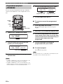
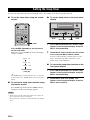
Basic receiver operation
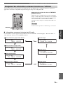
16 En
You can enjoy playing back various input sources on this
unit. After connecting speakers, antennas, or other
component, follow the procedures below to select the
input source you want to play. For information on
connection methods, see pages 12 and 13.
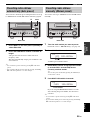
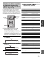
Perform one of the following operations.
To switch to CD input
Press CD.
To switch to tuner input (FM/AM radio)
Press TUNER.
y
Each time you press BAND, the input source switches
between FM and AM.
To switch to USB input
Press USB.
To switch to external source input
(external component connected to this unit)
Press AUX.
To switch to portable audio input
Press PORTABLE.
■ To select an input source using INPUT
on the front panel
Press INPUT repeatedly.
Each time you press INPUT, the input source changes
as follows.
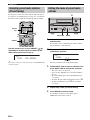
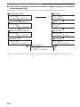
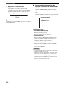
Press VOLUME + to increase the volume level and
VOLUME – to decrease.
y
You can also adjust the volume level by rotating VOLUME
on the front panel.
■ Muting the sound (MUTE)
Press MUTE to turn off the sound.
To restore the sound, press MUTE again or press
VOLUME +/–.
Basic receiver operation
Selecting the input source
PRESET
VOLUME
MUTE
TUNER
CD
BAND
PORTABLE
AUX
USB
AUX
USB
CD
TUNER
PORTABLE
BAND
Adjusting the volume level
CD
FM
AM
USB
AUX
PORTABLE
CD
BAND
PORTABLE
AUX
USB
PRESET VOLUME
TUNER
MUTE
MUTE
VOLUME +/–
La page est en cours de chargement...
La page est en cours de chargement...
La page est en cours de chargement...
La page est en cours de chargement...
La page est en cours de chargement...
La page est en cours de chargement...
La page est en cours de chargement...
La page est en cours de chargement...
La page est en cours de chargement...
La page est en cours de chargement...
La page est en cours de chargement...
La page est en cours de chargement...
La page est en cours de chargement...
La page est en cours de chargement...
La page est en cours de chargement...
La page est en cours de chargement...
La page est en cours de chargement...
La page est en cours de chargement...
La page est en cours de chargement...
La page est en cours de chargement...
La page est en cours de chargement...
La page est en cours de chargement...
La page est en cours de chargement...
La page est en cours de chargement...
La page est en cours de chargement...
La page est en cours de chargement...
La page est en cours de chargement...
La page est en cours de chargement...
La page est en cours de chargement...
La page est en cours de chargement...
La page est en cours de chargement...
La page est en cours de chargement...
La page est en cours de chargement...
La page est en cours de chargement...
La page est en cours de chargement...
La page est en cours de chargement...
La page est en cours de chargement...
La page est en cours de chargement...
La page est en cours de chargement...
La page est en cours de chargement...
La page est en cours de chargement...
La page est en cours de chargement...
La page est en cours de chargement...
La page est en cours de chargement...
La page est en cours de chargement...
La page est en cours de chargement...
La page est en cours de chargement...
La page est en cours de chargement...
La page est en cours de chargement...
La page est en cours de chargement...
La page est en cours de chargement...
La page est en cours de chargement...
La page est en cours de chargement...
La page est en cours de chargement...
La page est en cours de chargement...
La page est en cours de chargement...
La page est en cours de chargement...
La page est en cours de chargement...
La page est en cours de chargement...
La page est en cours de chargement...
La page est en cours de chargement...
La page est en cours de chargement...
La page est en cours de chargement...
La page est en cours de chargement...
La page est en cours de chargement...
La page est en cours de chargement...
-
 1
1
-
 2
2
-
 3
3
-
 4
4
-
 5
5
-
 6
6
-
 7
7
-
 8
8
-
 9
9
-
 10
10
-
 11
11
-
 12
12
-
 13
13
-
 14
14
-
 15
15
-
 16
16
-
 17
17
-
 18
18
-
 19
19
-
 20
20
-
 21
21
-
 22
22
-
 23
23
-
 24
24
-
 25
25
-
 26
26
-
 27
27
-
 28
28
-
 29
29
-
 30
30
-
 31
31
-
 32
32
-
 33
33
-
 34
34
-
 35
35
-
 36
36
-
 37
37
-
 38
38
-
 39
39
-
 40
40
-
 41
41
-
 42
42
-
 43
43
-
 44
44
-
 45
45
-
 46
46
-
 47
47
-
 48
48
-
 49
49
-
 50
50
-
 51
51
-
 52
52
-
 53
53
-
 54
54
-
 55
55
-
 56
56
-
 57
57
-
 58
58
-
 59
59
-
 60
60
-
 61
61
-
 62
62
-
 63
63
-
 64
64
-
 65
65
-
 66
66
-
 67
67
-
 68
68
-
 69
69
-
 70
70
-
 71
71
-
 72
72
-
 73
73
-
 74
74
-
 75
75
-
 76
76
-
 77
77
-
 78
78
-
 79
79
-
 80
80
-
 81
81
-
 82
82
-
 83
83
-
 84
84
-
 85
85
-
 86
86


Yamaha CRX-E320 Le manuel du propriétaire
- Catégorie
- Lecteur CD
- Taper
- Le manuel du propriétaire
dans d''autres langues
- English: Yamaha CRX-E320 Owner's manual
Documents connexes
-
Yamaha CDX-397MK Le manuel du propriétaire
-
Yamaha MCR-B020 Le manuel du propriétaire
-
-
-
Yamaha CRX-E320 Le manuel du propriétaire
-
-
Yamaha RX-V563 Le manuel du propriétaire
-
-
Yamaha pianocraft e730 Le manuel du propriétaire
-
Yamaha RX-E410 Le manuel du propriétaire

