Valor DVA5BV Le manuel du propriétaire
- Catégorie
- Cheminées
- Taper
- Le manuel du propriétaire

The DVA5BV kit is intended to allow listed direct vent
appliances to be installed on existing 5” B-vent systems
by inserting a 3” aluminum flex liner within the B-vent
and utilizing the space between the flex and B-vent for
incoming combustion air.
The DVA5BV is approved for use with Valor natural gas
heater models 530, 534, 650, 1000, 1100 and 1150 only.
The dimensions of the appliance and the clearances
to combustibles are listed in the installation manuals
packaged with the appliance. Make special note of
hearth requirements when using the 1000, 1100 or
1150 heater models.
It is the installer’s responsibility to:
• Verify the integrity of the existing vent and the
vent configuration to ensure the vent is adequately
supported and the existing 1-inch minimum
clearances are maintained before and after the
conversion to direct vent is completed.
• Ensure the feasibility of installing the 3-inch liner
within the existing vent without damage to the
existing system before irreversibly damaging/
removing any part of the existing system. Miles
Industries Ltd. will assume no responsibility under
such instances.
(An inspection camera is recommended to help verify/
ensure the integrity of the vent and feasibility of the
installation.)
The use of the DVA5BV does not affect any other aspect
of the appliance installation other than the venting
and restrictor settings. Refer to the next pages and the
installation instructions packed with the appliance.
The listed direct vent models may only be installed onto
B-vent systems using approved adapters packaged with
this kit and following these instructions. Ensure the
3-inch aluminum flex liners are completely enclosed
within the existing B-vent. Existing B-vent may be
extended to adapter location where required using
B-vent from the same manufacturer.
Do not use single wall pipe to install liners into.
Kit Contents
Upper Adapter
Flared
inner
pipe
Lower Adapter
Conversion label
This appliance has been adapted
to work on a “Special Venting System”
utilizing a
DVA5BV kit to adapt an
existing 5“ B-vent to a direct vent system
by installing a 3” ex liner within the B-vent.
The appliance specications and clearances are unchanged.
Refer to
DVA5BV Instruction Manual for details.
4005490-03
© Copyright Miles Industries Ltd., 2019
Note: This kit must be installed or serviced
by a qualified installer, service agency
or gas supplier. These instructions are
to be used in conjunction with the main
installation instructions for the above
listed models.
DVA5BV—Direct Vent Adapter to 5” B-Vent
Use ONLY with Valor Natural Gas Fireplace Models 530, 534, 650,
1000, 1100 and 1150 (NOT compatible with 530INI insert model)
INSTALLATION INSTRUCTIONS
DVA5BV
WARNING
If these instructions are not followed
exactlly, a fire or explosion may result
causing property damage, personal
injury or loss of life.
Please leave this manual with the homeowner.

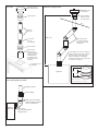
Standard 6-5/8 x 4
vertical termination
Upper Adapter
Existing
5” B-vent
3” dia. alum.
ȵH[OLQHU
(not supplied)
Lower Adapter
New 6-5/8 x 4
Duravent pipe
length as required
or adapter can be
installed directly
on appliance and
B-vent extended as
necessary
Listed Direct Vent
Appliance
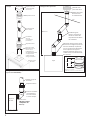
Overview Allowable Confi gurations
Alternate Rear Outlet Confi guration
(530 model appliances ONLY)
New Direct Vent
Termination
Upper adapter
directly on top
of existing vent
Existing 5” B-vent -
DQ\RVHWVVKRXOG
be 45° to allow liner
installation
Roof
/RZHUDGDSWHUFDQPRXQWGLUHFWO\WR
DSSOLDQFHWRSRXWOHWRQO\RUKLJKHU
XSZLWK['XUDYHQWSLSH
between adapter and appliance.
Install lower adapter on vertical pipe
or max. 45° off vertical.
Appliance
Max. 40’-0”
6-1/4”
2-1/2”
3-3/4”
Lower Adapter
(Upper Adapter is similar)
Existing 5” B-vent
Lower adapter
New 6-5/8 x 4 Duravent
pipe and elbow installed
at rear of appliance
530 ONLY
Rear outlet
(DO NOT install lower
adapter here!)
Appliance
side view
2

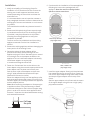
Installation
1. Verify the suitability of the existing B-vent for
installation of a 3” aluminum flex liner. Ensure the
existing vent is well supported and there are no
screws penetrating the vent which could tear the
aluminum liner.
It is recommended to use an inspection camera or
drop a weighted line down the vent to determine the
total length of the vent and whether or not there are
any offsets.
This should be done before any destructive work is
done.
2. Remove and discard existing B-vent cap and rough-
in new aluminum flex liner into the existing B-vent.
If possible, it may be preferred to do this before
removing the existing appliance to verify that
installation is possible.
The liner can then be pulled back and the existing
appliance removed once the liner installation is
verified.
3. Remove the existing appliance without damaging the
lower portion of the existing B-vent.
4. Determine where the lower adapter will be
positioned and either extend venting from the
appliance using a 6-5/8 x 4” Duravent pipe or extend
the existing B-vent to the adapter located on the
appliance. Do not install lower adapter horizontally.
Install lower adapter on vertical pipe
or maximum 45 degrees off vertical.
5. Fasten the 3” aluminum liner to the collar on the
lower adapter using sheet metal screws and slide the
lower adapter over the lower end of the B-vent.
Seal the outer collar of the adapter to the B-vent
using 2” wide self-adhesive aluminum foil tape
(Nashua 322-2 brand or similar).
Mount the adapter directly over the appliance collar
and secure with sheet metal screws or use 6-5/8 x 4”
Duravent pipe(s) as necessary between the appliance
and the adapter position.
Note: When mounting the adapter or Duravent pipe
to appliance collars it may be necessary to flatten
the twistlock dimples on the inside of the pipe using
pliers in order to fit over the outer appliance collar.
Ensure a 1” clearance is maintained between venting
and combustible material.
6. Continue with the installation of the new appliance
following the instructions packaged with the
appliance. Note the restrictor settings below
specific to these conversions.
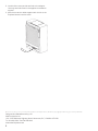
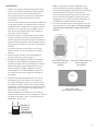
7. Install the upper adapter. Gently pull the aluminum
liner upwards and trim any excess liner. Fasten the
liner to the upper adapter using sheet metal screws
and drop the upper adapter over the top of the
B-vent.
Seal the upper adapter to the B-vent and the seams
of the upper adapter using silicone or high quality
polyurethane sealant.
530, except w/coals
(any length vent)
1000, 1100 & 1150
(any length vent)
530 w/coals, 534 & 650
(any length vent)
Foil tape
the joint
No restrictor
No restrictor
No restrictor
3

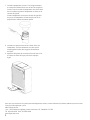
8. Install a direct vent vertical terminal to the adapter.
Use only terminals listed in the appliance installation
manual.
9. Affix the conversion label supplied with this kit to the
fireplace bottom near the valve.
This appliance has been adapted
to work on a “Special Venting System”
utilizing a
DVA5BV
kit to adapt an
existing 5“ B-vent to a direct vent system
by installing a 3” ex liner within the B-vent.
The appliance specications and clearances are unchanged.
Refer to
DVA5BV
Instruction Manual for details.
This appliance has been adapted
to work on a “Special Venting System”
utilizing a
DVA5BV
kit to adapt an
existing 5“ B-vent to a direct vent syste
by installing a 3” ex liner withinth
The appliance specications
Refer to
DVA5BV
Inst
Th
Designed and Manufactured by / for
Miles Industries Ltd.
190 – 2255 Dollarton Highway, North Vancouver, B.C., CANADA V7H 3B1
Tel. 604-984-3496 Fax 604-984-0246
www.valorfireplaces.com
Because our policy is one of constant development and improvement, details may vary slightly from those given in this publication.
4

Le kit d’adaptateurs DVA5BV est conçu afin de
permettre le raccordement d’un foyer à évent direct
listé à un système d’évacuation de type B de 5 pouces.
Ce raccordement se fait en insérant un conduit flex en
aluminium de 3 pouces de diamètre dans le conduit
de type B utilisant l’espace entre les deux conduits pour
l’air de combustion entrant.
Le DVA5BV est homologué pour utilisation avec les
foyers Valor au gaz naturel 530, 534, 650, 1000, 1100 et
1150 seulement.
Les dimensions de l’appareil et les dégagements aux
combustibles sont indiqués dans les guides d’installation
du foyer. Prenez note des exigences quant à la dalle de
protection lorsque vous installez les foyers 1000, 1100
ou 1150.
L’installateur est responsable de :
• Vérifier l’intégrité du système d’évacuation existant et
de sa configuration avant et après la conversion afin
de s’assurer que le conduit d’évacuation est supporté
convenablement et que le dégagement minimum de
1 pouce est maintenu.
• S’assurer de la faisabilité de l’installation d’un con-
duit flex de 3 pouces de diamètre dans le conduit
d’évacuation existant avant de l’endommager de
façon irréversible ou d’enlever des pièces du système
existant. Miles Industries Ltd. n’assumera aucune
responsabilité dans ces circonstances.
(Une caméra d’inspection est recommandée afin
de vérifier et de s’assurer de l’intégrité du conduit
d’évacuation et de la faisabilité de l’installation.)
L’utilisation du DVA5BV n’affecte pas les autres aspects
de l’installation de l’appareil autre que l’évacuation et
le réglage des restricteurs d’air. Consultez les pages
suivantes et le guide d’installation fourni avec le foyer.
Les foyers à évent direct listés peuvent être installés
dans un système d’évent de type B seulement avec les
adaptateurs de ce kit et selon les directives fournies
avec ce kit. Assurez-vous que le conduit flex d’aluminium
de 3 pouces de diamètre est complètement inséré dans
le conduit existant de type B. Le conduit existant de
type B peut être allongé pour rejoindre les adaptateurs
si nécessaire en utilisant un autre conduit de type B du
même fabricant.
Ne pas installer le conduit flex dans un conduit à paroi
simple.
Contenu du kit
Adaptateur du haut
Paroi intérieure
évasée
Adaptateur
du bas
Étiquette de
conversion
This appliance has been adapted
to work on a “Special Venting System”
utilizing a
DVA5BV kit to adapt an
existing 5“ B-vent to a direct vent system
by installing a 3” ex liner within the B-vent.
The appliance specications and clearances are unchanged.
Refer to
DVA5BV Instruction Manual for details.
© Copyright Miles Industries Ltd., 2019
5
Adaptateur d’évent direct à évent conventionnel 5” (B-Vent)
Utilisez SEULEMENT avec les modèles de foyers Valor au gaz naturel suivants : 530,
534, 650, 1000, 1100 et 1150 (Incompatible avec modèle encastrable 530INI)
GUIDE D’INSTALLATION
DVA5BV
Note : Ce kit doit être installé et entretenu
par un installateur qualifié, une agence
de service certifiée ou un fournisseur de
gaz. Ces instructions doivent être utilisées
conjointement avec les instructions
d’installation des foyers Valor listés.
AVERTISSEMENT
Si les instructions de ce guide ne
sont pas suivies à la lettre, un feu ou
une explosion pourraient résulter et
causer des dommages matériels, des
blessures ou la mort.
Veuillez laisser cette notice au
propriétaire du foyer.

Capuchon de sortie
verticale standard
de 6-5/8 x 4
Adaptateur du haut
Conduit de type B
de 5” existant
Conduit ex
de 3” dia.
en alumimium
(non fourni)
Adaptateur du bas
Nouveau conduit
DuraVent 6-5/8 x 4
selon le cas ou
l’adaptateur peu
être installé directement
sur l’appareil et le
conduit de type B
allongé si nécessaire
Foyer à évent
direct listé
Concept Confi gurations permises
Confi guration alternative pour évent à l’arrière
(foyers 530 SEULEMENT)
Nouvelle sortie
pour évent direct
Adaptateur du haut
directement sur
le conduit existant
Conduit de type B
existant - tout décalage
devrait être de 45° afin
de permettre l’installation
du conduit flex
Toit
Adaptateur du bas peut être monté
directement sur l’appareil (évent sur
le dessus seulement) ou plus haut
avec un conduit 6-5/8 x 4 DuraVent
entre l’adaptateur et l’appareil.
Installez l’adaptateur du bas sur un
conduit vertical ou au maximum 45°
de la verticale.
Foyer
Max. 40’-0”
6-1/4”
2-1/2”
3-3/4”
Adaptateur du bas
(Adaptateur du haut est similaire)
Conduit de type B
5” existant
Adaptateur du bas
Nouveau conduit et
coude DuraVent
6-5/8 x 4 installés
à l’arrière du foyer
530 SEULEMENT
Évent arrière
(NE PAS installer
l’adaptateur du
bas ici!)
Foyer vu
de côté
6

Installation
1. Vérifiez si le système d’évacuation de type B peut
recevoir un conduit flex d’aluminium de 3 pouces.
Assurez-vous que le système d’évacuation est
bien supporté et qu’il n’y ait pas de vis pénétrant
le conduit qui pourraient déchirer le conduit
d’aluminium.
Il est recommandé d’utiliser une caméra d’inspection
ou de laisser tomber un fil plombé dans le conduit
d’évacuation pour déterminer la longueur totale du
conduit et si il y a présence de décalages ou non.
Ceci devrait être effectué avant que le travail de
conversion ne soit entrepris.
2. Enlevez et jetez ou recyclez le capuchon de sortie
de type B existant puis insérez sommairement le
conduit flex dans le conduit de type B. Si possible, il
serait préférable de le faire avant d’enlever le foyer
existant pour vous assurer que cette installation est
possible.
Le conduit flex peut ensuite être tiré et le foyer
existant enlevé une fois l’installation du conduit
vérifiée.
3. Enlevez le foyer existant sans endommager la
portion du bas du conduit de type B.
4. Déterminez où l’adaptateur du bas sera placé et
allongez le conduit à partir de l’appareil avec un
conduit DuraVent 6-5/8 x 4” ou allongez le conduit
existant de type B jusqu’à l’adaptateur situé sur
l’appareil. Ne pas installer l’adaptateur du bas
horizontalement. Installez l’adapteur du bas sur
un conduit vertical ou à 45 degrés maximum de
la verticale.
5. Fixez le conduit flex d’aluminium de 3” à la buse
de l’adapteur du bas à l’aide de vis à métaux et
raccorder l’adaptateur du bas en couvrant le bout
du conduit de type B. Scellez la buse extérieure de
l’adaptateur au conduit de type B à l’aide d’un ruban
d’aluminium auto-collant de 2” de large (marque
Nashua 322-2 ou similaire).
Montez l’adaptateur directement sur la buse de
l’appareil et fixez-le avec des vis à métaux ou utilisez
un conduit DuraVent 6-5/8 x 4” entre l’appareil et
l’adaptateur selon le cas.
Note : Lorsque vous montez l’adaptateur ou le
conduit DuraVent aux buses de l’appareil, il peut
être nécessaire d’applatir les alvéoles du mécanisme
d’enclenchement à l’intérieur du conduit en
utilisant des pinces afin de pouvoir l’installer sur la
buse extérieure de l’appareil. Assurez-vous qu’un
dégagement de 1” entre le conduit d’évacuation et
les matériaux combustibles soit maintenu.
6. Continuez l’installation du nouvel appareil selon les
directives fournies avec l’appareil. Notez le réglage
des restricteurs spécifique à cette conversion ci-
dessous.
530, sauf avec charbons
(toutes longueurs de
conduits)
1000, 1100 et 1150
(toutes longueurs de conduits)
530 avec charbons, 534 & 650
(toutes longueurs
de conduits)
Scellez le
joint avec
du ruban
d’aluminium
Pas de restricteur
Pas de
restricteur
Pas de
restricteur
7

7. Installez l’adaptateur du haut. Tirez soigneusement
le conduit flex d’aluminium vers le haut et coupez-en
l’excès. Fixez le conduit à l’adaptateur du haut à l’aide
de vis à métaux et placez l’adaptateur du haut sur le
conduit de type B.
Scellez l’adaptateur du haut au conduit de type B et
les joints de l’adaptateur à l’aide de silicone ou de
polyuthérane scellant de haute qualité.
8. Installez un capuchon de sortie à évent direct sur
l’adaptateur. Utilisez seulement une des sorties
homologuées listées dans le guide d’installation
du foyer.
9. Apposez l’étiquette de conversion fournie avec ce kit
à la paroi du fond du foyer près de la soupape
à gaz.
This appliance has been adapted
to work on a “Special Venting System”
utilizing a
DVA5BV
kit to adapt an
existing 5“ B-vent to a direct vent system
by installing a 3” ex liner within the B-vent.
The appliance specications and clearances are unchanged.
Refer to
DVA5BV
Instruction Manual for details.
This appliance has been adapted
to work on a “Special Venting System”
utilizing a
DVA5BV
kit to adapt an
existing 5“ B-vent to a direct vent syste
by installing a 3” ex liner withinth
The appliance specications
Refer to
DVA5BV
Inst
Th
SCELLANT
Conçue et fabriquée par / pour
Miles Industries Ltd.
190 – 2255 Dollarton Highway, North Vancouver, BC, CANADA V7H 3B1
Tél. 604-984-3496 Téléc. 604-984-0246
www.foyervalor.com
Parce que nous favorisons une politique de développement continu, certains détails de la présente publication peuvent varier.
8
-
 1
1
-
 2
2
-
 3
3
-
 4
4
-
 5
5
-
 6
6
-
 7
7
-
 8
8


Valor DVA5BV Le manuel du propriétaire
- Catégorie
- Cheminées
- Taper
- Le manuel du propriétaire
dans d''autres langues
- English: Valor DVA5BV Owner's manual
Documents connexes
Autres documents
-
Fireplace Xtrordinair 864 See Through GS2 Guide d'installation
-
NAPOLEON Bayfield GDS25N-1 Le manuel du propriétaire
-
Continental Fireplaces CDVS600-1NSB Le manuel du propriétaire
-
-
-
NAPOLEON GDS50-1PSB Manuel utilisateur
-
-