Yamaha n12 Le manuel du propriétaire
- Catégorie
- Matériel musical
- Taper
- Le manuel du propriétaire
Ce manuel convient également à

ES
FR
DE
EN
Owner's Manual
Bedienungsanleitung
Mode d'emploi
Manual de instrucciones
EnglishDeutschFrançaisEspañol

The above warning is located on the rear of the unit.
Explanation of Graphical Symbols
The lightning flash with arrowhead symbol
within an equilateral triangle is intended to alert
the user to the presence of uninsulated
“dangerous voltage” within the product’s
enclosure that may be of sufficient magnitude to
constitute a risk of electric shock to persons.
The exclamation point within an equilateral
triangle is intended to alert the user to the
presence of important operating and
maintenance (servicing) instructions in the
literature accompanying the product.
IMPORTANT SAFETY INSTRUCTIONS
1 Read these instructions.
2Keep these instructions.
3 Heed all warnings.
4 Follow all instructions.
5 Do not use this apparatus near water.
6 Clean only with dry cloth.
7 Do not block any ventilation openings. Install in
accordance with the manufacturer’s instructions.
8 Do not install near any heat sources such as radiators,
heat registers, stoves, or other apparatus (including
amplifiers) that produce heat.
9 Do not defeat the safety purpose of the polarized or
grounding-type plug. A polarized plug has two blades
with one wider than the other. A grounding type plug
has two blades and a third grounding prong. The wide
blade or the third prong are provided for your safety. If
the provided plug does not fit into your outlet, consult
an electrician for replacement of the obsolete outlet.
10 Protect the power cord from being walked on or pinched
particularly at plugs, convenience receptacles, and the
point where they exit from the apparatus.
11 Only use attachments/accessories specified by the
manufacturer.
12 Use only with the cart, stand,
tripod, bracket, or table specified
by the manufacturer, or sold with
the apparatus. When a cart is
used, use caution when moving
the cart/apparatus combination
to avoid injury from tip-over.
13 Unplug this apparatus during
lightning storms or when unused for long periods of
time.
14 Refer all servicing to qualified service personnel.
Servicing is required when the apparatus has been
damaged in any way, such as power-supply cord or plug
is damaged, liquid has been spilled or objects have
fallen into the apparatus, the apparatus has been
exposed to rain or moisture, does not operate normally,
or has been dropped.
(98-6500)
CAUTION: TO REDUCE THE RISK OF
ELECTRIC SHOCK, DO NOT REMOVE
COVER (OR BACK). NO USER-SERVICEABLE
PARTS INSIDE. REFER SERVICING TO
QUALIFIED SERVICE PERSONNEL.
CAUTION
RISK OF ELECTRIC SHOCK
DO NOT OPEN
WARNING
TO REDUCE THE RISK OF FIRE OR ELECTRIC SHOCK, DO NOT EXPOSE THIS APPARATUS TO RAIN OR MOISTURE.

1. IMPORTANT NOTICE: DO NOT MODIFY THIS UNIT!
This product, when installed as indicated in the instructions con-
tained in this manual, meets FCC requirements. Modifications not
expressly approved by Yamaha may void your authority, granted by
the FCC, to use the product.
2. IMPORTANT:
When connecting this product to accessories and/
or another product use only high quality shielded cables. Cable/s
supplied with this product MUST be used. Follow all installation
instructions. Failure to follow instructions could void your FCC
authorization to use this product in the USA.
3. NOTE:
This product has been tested and found to comply with the
requirements listed in FCC Regulations, Part 15 for Class “B” digital
devices. Compliance with these requirements provides a reason-
able level of assurance that your use of this product in a residential
environment will not result in harmful interference with other elec-
tronic devices. This equipment generates/uses radio frequencies
and, if not installed and used according to the instructions found in
the users manual, may cause interference harmful to the operation
of other electronic devices. Compliance with FCC regulations does
* This applies only to products distributed by YAMAHA CORPORATION OF AMERICA. (class B)
not guarantee that interference will not occur in all installations. If
this product is found to be the source of interference, which can be
determined by turning the unit “OFF” and “ON”, please try to elimi-
nate the problem by using one of the following measures:
Relocate either this product or the device that is being affected by
the interference.
Utilize power outlets that are on different branch (circuit breaker or
fuse) circuits or install AC line filter/s.
In the case of radio or TV interference, relocate/reorient the
antenna. If the antenna lead-in is 300 ohm ribbon lead, change the
lead-in to co-axial type cable.
If these corrective measures do not produce satisfactory results,
please contact the local retailer authorized to distribute this type of
product. If you can not locate the appropriate retailer, please con-
tact Yamaha Corporation of America, Electronic Service Division,
6600 Orangethorpe Ave, Buena Park, CA90620
The above statements apply ONLY to those products distributed by
Yamaha Corporation of America or its subsidiaries.
FCC INFORMATION (U.S.A.)
The serial number of this product may be found on the rear of
the unit. You should note this serial number in the space pro-
vided below and retain this manual as a permanent record of
your purchase to aid identification in the event of theft.
Model No.
Serial No.
(rear)
* This applies only to products distributed by
YAMAHA CORPORATION OF AMERICA.
COMPLIANCE INFORMATION STATEMENT
(DECLARATION OF CONFORMITY PROCEDURE)
Responsible Party : Yamaha Corporation of America
Address : 6600 Orangethorpe Ave., Buena Park, Calif. 90620
Telephone : 714-522-9011
Type of Equipment : Digital Mixing Studio
Model Name : n8/n12
This device complies with Part 15 of the FCC Rules.
Operation is subject to the following conditions:
1) this device may not cause harmful interference, and
2) this device must accept any interference received including interference
that may cause undesired operation.
See user manual instructions if interference to radio reception is suspected.
(FCC DoC)
OBSERVERA!
Apparaten kopplas inte ur växelströmskällan (nätet) så länge
som den ar ansluten till vägguttaget, även om själva apparaten
har stängts av.
ADVARSEL:
Netspæendingen til dette apparat er IKKE
afbrudt, sålæenge netledningen siddr i en stikkontakt, som er t
endt — også selvom der or slukket på apparatets afbryder.
VAROITUS:
Laitteen toisiopiiriin kytketty käyttökytkin ei irroita
koko laitetta verkosta.
(standby)
IMPORTANT
Please record the serial number of this unit in the space below.
Model:
Serial No.:
The serial number is located on the bottom or rear of the unit.
Retain this Owner's Manual in a safe place for future
reference.
(Ser. No)* This applies only to products distributed by
YAMAHA CORPORATION OF AMERICA
IMPORTANT NOTICE FOR THE UNITED KINGDOM
Connecting the Plug and Cord
IMPORTANT. The wires in this mains lead are coloured in accordance
with the following code:
BLUE : NEUTRAL
BROWN : LIVE
As the colours of the wires in the mains lead of this apparatus may not
correspond with the coloured makings identifying the terminals in your
plug proceed as follows:
The wire which is coloured BLUE must be connected to the terminal
which is marked with the letter N or coloured BLACK.
The wire which is coloured BROWN must be connected to the termi-
nal which is marked with the letter L or coloured RED.
Making sure that neither core is connected to the earth terminal of the
three pin plug.
• This applies only to products distributed by Yamaha-Kemble Music (U.K.) Ltd. (2 wires)

Owner’s Manual
4
English
Welcome .......................................... 5
Features ........................................... 5
Included items (please check) ....... 5
Turning On and Off the Power to the
Mixer ................................................ 8
Before Turning On the Power to the Mixer .............. 8
Turning the Power On and Off ................................ 8
Recording Basics ............................ 9
Techie Words? Don’t Be Afraid. .............................. 9
Signals — Level and Decibel ............................ 9
Balanced or Unbalanced? ................................ 9
How balanced lines work .................................. 9
How unbalanced lines work ............................ 10
Connector Variations ....................................... 10
Phone connectors ........................................... 10
RCA pin connectors ........................................ 10
Inside Your Mixer .................................................. 11
Basic Structure ................................................ 11
Monitor mix for musicians, external effects ..... 12
Front and Rear Panels ................... 13
Channel Control section ........................................ 13
Master Control section .......................................... 16
Meter section ......................................................... 17
Control Room section ............................................ 18
DAW Remote Control section ............................... 19
Rear I/O section .................................................... 20
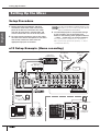
Setting Up the Mixer ..................... 22
Setup Procedure ................................................... 22
n12 Setup Example (Home recording) .................. 22
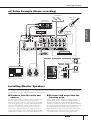
n8 Setup Example (Home recording) .................... 23
Installing Monitor Speakers ................................... 23
A Hands-On Guide to the n8/n12 ... 24
Let’s Hear It! .......................................................... 24
Connecting sound sources and monitor devices
24
Adjusting the gain ........................................... 24
Setting up the monitoring environment ........... 25
Adjusting the volume level .............................. 26
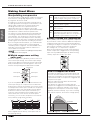
Making Great Mixes .............................................. 28
Manipulating compression .............................. 28
Mastery of EQ .................................................. 29
Panning and balancing ................................... 30
Mixing into stereo ............................................ 30
Applying reverb ............................................... 31
Soloing a channel ............................................ 32
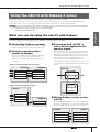
Using the n8/n12 with
Cubase 4 series ............................ 33
What you can do using the n8/n12 with Cubase ... 33
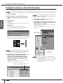
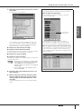
Computer setup for the Link function .................... 34
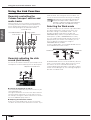
Using the Link Function ......................................... 36
Remotely controlling the Cubase transport section
and audio tracks ............................................. 36
Remotely adjusting the click sound (metronome)
36
Selecting the Work mode ................................ 36
Let’s start our recording session! .......................... 39
Mixing signals on the n8/n12, then recording . 39
Recording n8/n12 input channel signals directly to
Cubase ............................................................ 41
Mixing recorded tracks .......................................... 43
Mixing audio tracks ......................................... 43
Mixing down .................................................... 45
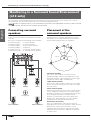
Monitoring in a Surround Sound
Environment (n12 only) .................. 46
Connecting surround speakers ............................. 46
Placement of the surround speakers .................... 46
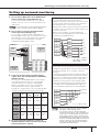
Setting up surround monitoring ............................. 47
Replacing the Sweet Spot Data .... 48
Using the n8/n12 with Software Other
Than Cubase .................................. 49
Using the n8/n12 with a DAW other than Cubase . 49
Audio Driver Setup .......................................... 49
MIDI Driver Setup ............................................ 49
Using the n8/n12 along with a multimedia application
51
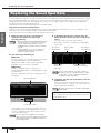
Troubleshooting ............................. 53
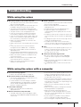
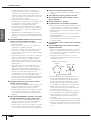
While using the mixer ............................................ 53
While using the mixer with a computer ................. 53
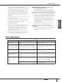
Error Messages ..................................................... 55
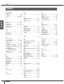
Index .............................................. 56
Appendix ........................................ 57
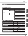
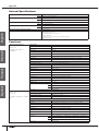
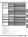
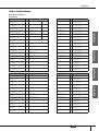
Specifications ........................................................ 57
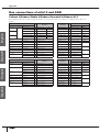
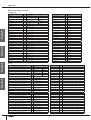
Bus connections of n8/n12 and DAW ................... 60
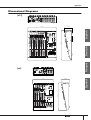
Dimensional Diagrams .......................................... 63
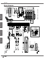
Block Diagram ....................................................... 64
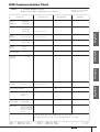
MIDI Implementation Chart ................................... 65
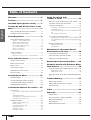
Table of Contents

Welcome
Owner’s Manual
5
English
Thank you for purchasing the Yamaha n8/n12 Digital Mixing Studio. The n8/n12 is a comprehensive music production system
that packages a digital mixer featuring easy yet full-fledged recording/mixdown operations with the cutting-edge DAW software
Cubase AI 4. Connecting a computer to the mixer’s IEEE 1394 port enables you to configure an ideal recording environment.
Please read this Owner’s Manual before you start using the n8/n12 so that you can take full advantage of the mixer’s superlative
features and enjoy trouble-free operation for years to come. Also, keep this book in a safe place for future reference.
Ease of operation
Analog-like mixing interface ensures intuitive operation.
High-quality sound
Based on an examination of existing head amp circuits, a new head amp circuit has been developed to provide higher
quality and superior musical characteristics.
Mixer functions
The mixer can handle up to 16 channel inputs (n12) or 12 channel inputs (n8), mixing them to stereo outputs. Each
monaural input jack features an XLR jack with a phantom power supply, which enables you to connect a wide range of
instruments and devices, from condenser microphones to synthesizers and other line-level instruments. Input channel 8
(n12) and Input channel 4 (n8) support Hi-Z input for direct connection of an electric guitar or bass.
Computer connection via a single IEEE 1394 cable
Connect a computer with an IEEE 1394 port to the n8/n12 using an IEEE 1394 cable to transfer audio and MIDI signals
between the mixer and Steinberg Cubase or other DAW.
* In order to monitor in a surround environment, you will need a surround-capable application such as Cubase 4. The included
Cubase AI 4 does not support surround.
Link with Cubase
Install Cubase AI 4 on the computer, and the n8/n12 will link to Cubase and operate together seamlessly. For example, you
can record the n8/n12 input signals to Cubase as is, or mix Cubase audio tracks on the n8/n12. You can also turn on and
off the monitor for the VST effects or control the transport section and tracks remotely from the n8/n12. In addition, Purchase
the separately-available Cubase 4 and use it with the n8/n12 to enjoy advanced functionality such as surround.
Control Room monitoring function
The n8/n12 features a monitoring function dedicated to the Control Room (Control Room Monitor function). You can
connect one (n8) or three (n12) monitoring speakers to the mixer. If a computer is connected to the n12, you can
monitor the sound from Cubase or another DAW in a surround sound environment.
Newly developed compressor
The n8/n12 includes a newly developed compressor that adopts Sweet Spot Morphing technology. The mixer provides
various compressor presets that represent the distillation of extensive professional engineering experience, letting you
quickly and easily bring your sound to a professional standard.
Three-band EQ on each channel
Each input channel features a full 3-band (high/mid/low) equalizer, providing easy sound shaping to suit your preferences.
Digital reverb at your service
A built-in digital reverb can be assigned to all input channels. If a computer is connected to the mixer, you can also apply
digital reverberation to output from Cubase or another DAW, as well as to microphone and other instrumental sounds.
Power adaptor (n12= PA-30, n8=PA-20)*
* May not be included depending on your particular
area. Please check with your Yamaha dealer.
Owner’s Manual
IEEE 1394 cable
TOOLS for n Version2/Cubase AI 4 installation guide
TOOLS for n Version2 CD-ROM
Cubase AI 4 DVD-ROM
Welcome
Features
Included items (please check)
Please read the software license agreement before
you unseal the included discs. The software license
agreement is given at the end of the TOOLS for n
Version2/Cubase AI 4 installation guide.
NOTE

PRECAUTIONS
Owner’s Manual
6
English
PRECAUTIONS
PLEASE READ CAREFULLY BEFORE PROCEEDING
* Please keep this manual in a safe place for future reference.
WARNING
Always follow the basic precautions listed below to avoid the possibility of serious injury or even death from electrical
shock, short-circuiting, damages, fire or other hazards. These precautions include, but are not limited to, the following:
• Only use the voltage specified as correct for the device. The required voltage is
printed on the name plate of the device.
• Use only the included AC power adaptor (*PA-30 for the n12, PA-20 for the n8
or an equivalent recommended by Yamaha).
• Do not place the power cord near heat sources such as heaters or radiators,
and do not excessively bend or otherwise damage the cord, place heavy objects
on it, or place it in a position where anyone could walk on, trip over, or roll
anything over it.
• Do not open the device or attempt to disassemble the internal parts or modify
them in any way. The device contains no user-serviceable parts. If it should
appear to be malfunctioning, discontinue use immediately and have it
inspected by qualified Yamaha service personnel.
• Do not expose the device to rain, use it near water or in damp or wet
conditions, or place containers on it containing liquids which might spill into
any openings.
If any liquid such as water seeps into the device, turn off the power immediately
and unplug the power cord from the AC outlet. Then have the device inspected
by qualified Yamaha service personnel.
• Never insert or remove an electric plug with wet hands.
• If the power cord or plug becomes frayed or damaged, or if there is a sudden
loss of sound during use of the device, or if any unusual smells or smoke
should appear to be caused by it, immediately turn off the power switch,
disconnect the electric plug from the outlet, and have the device inspected by
qualified Yamaha service personnel.
• If this device or the AC power adaptor should be dropped or damaged,
immediately turn off the power switch, disconnect the electric plug from the
outlet, and have the device inspected by qualified Yamaha service personnel.
CAUTION
Always follow the basic precautions listed below to avoid the possibility of physical injury to you or others, or damage
to the device or other property. These precautions include, but are not limited to, the following:
• Remove the electric plug from the outlet when the device is not to be used for
extended periods of time, or during electrical storms.
• When removing the electric plug from the device or an outlet, always hold the
plug itself and not the cord. Pulling by the cord can damage it.
•To avoid generating unwanted noise, make sure there is adequate distance
between the AC power adaptor and the device.
• Do not cover or wrap the AC power adaptor with a cloth or blanket.
• Before moving the device, remove all connected cables.
• When setting up the device, make sure that the AC outlet you are using is easily
accessible. If some trouble or malfunction occurs, immediately turn off the
power switch and disconnect the plug from the outlet. Even when the power
switch is turned off, electricity is still flowing to the product at the minimum
level. When you are not using the product for a long time, make sure to unplug
the power cord from the wall AC outlet.
•Avoid setting all equalizer controls and faders to their maximum. Depending on
the condition of the connected devices, doing so may cause feedback and may
damage the speakers.
• Do not expose the device to excessive dust or vibrations, or extreme cold or
heat (such as in direct sunlight, near a heater, or in a car during the day) to
prevent the possibility of panel disfiguration or damage to the internal
components.
• Do not place the device in an unstable position where it might accidentally fall
over.
• Do not block the vents. This device has ventilation holes at the top/bottom to
prevent the internal temperature from becoming too high. In particular, do not
place the device on its side or upside down. Inadequate ventilation can result in
overheating, possibly causing damage to the device(s), or even fire.
• Do not use the device in the vicinity of a TV, radio, stereo equipment, mobile
phone, or other electric devices. Doing so may result in noise, both in the
device itself and in the TV or radio next to it.
• Before connecting the device to other devices, turn off the power for all devices.
Before turning the power on or off for all devices, set all volume levels to
minimum.
Power supply/Power cord
Do not open
Water warning
If you notice any abnormality
Power supply/Power cord
Location
Connections

PRECAUTIONS
Owner’s Manual
7
English
• Remove the power plug from the AC outlet when cleaning the device.
• When turning on the AC power in your audio system, always turn on the power
amplifier LAST, to avoid speaker damage. When turning the power off, the
power amplifier should be turned off FIRST for the same reason.
• Do not insert your fingers or hands in any gaps or openings on the device
(vents, ports, etc.).
•Avoid inserting or dropping foreign objects (paper, plastic, metal, etc.) into any
gaps or openings on the device (vents, ports, etc.) If this happens, turn off the
power immediately and unplug the power cord from the AC outlet. Then have
the device inspected by qualified Yamaha service personnel.
• Do not apply oil, grease, or contact cleaner to the faders. Doing so may cause
problems with electrical contact or fader motion.
• Do not use the device or headphones for a long period of time at a high or
uncomfortable volume level, since this can cause permanent hearing loss. If
you experience any hearing loss or ringing in the ears, consult a physician.
• Do not rest your weight on the device or place heavy objects on it, and avoid
use excessive force on the buttons, switches or connectors.
Always turn the power off when the device is not in use.
Even when the power switch is in the “STANDBY” position, electricity is still flowing to the device at the minimum level. When you are not using the device for a long time,
make sure you unplug the power cord from the wall AC outlet.
The performance of components with moving contacts, such as switches, volume controls, and connectors, deteriorates over time. Consult qualified Yamaha service
personnel about replacing defective components.
The illustrations and LCD screens as shown in this owner’s manual are for instructional purposes only, and may appear somewhat different from those on your instrument.
This product incorporates and bundles computer programs and contents in which Yamaha owns copyrights or with respect to which it has license to use others' copyrights.
Such copyrighted materials include, without limitation, all computer software, music data, etc. Any unauthorized use of such programs and contents outside of personal use
is not permitted under relevant laws. Any violation of copyright has legal consequences. DON'T MAKE, DISTRIBUTE OR USE ILLEGAL COPIES.
Copying of the commercially available musical data including but not limited to MIDI data and/or audio data is strictly prohibited except for your personal use.
• Windows is the registered trademarks of Microsoft(R) Corporation.
• Apple, Mac and Macintosh are trademarks of Apple Inc., registered in the U.S. and other countries.
• FireWire and the FireWire symbol are trademarks of Apple, Inc., registered in the U.S. and other countries. The FireWire logo is a trademark of Apple, Inc.
• Steinberg and Cubase are the registered trademarks of Steinberg Media Technologies GmbH.
• The company names and product names in this Owner’s Manual are the trademarks or registered trademarks of their respective companies.
Maintenance
Handling caution
XLR-type connectors are wired as follows (IEC60268 standard): pin 1: ground, pin 2: hot (+), and pin 3: cold (-).
Insert TRS phone jacks are wired as follows: sleeve: ground, tip: send, and ring: return.
Yamaha cannot be held responsible for damage caused by improper use or modifications to the device, or data that is lost or destroyed.

Turning On and Off the Power to the Mixer
Owner’s Manual
8
English
Before Turning On the
Power to the Mixer
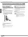
1.
Make sure that the mixer’s power switch is in the
STANDBY position.
2.
Connect the power adaptor to the AC INPUT
connector (
1
) on the rear panel of the mixer,
then turn the fastening ring clockwise (
2
) to
secure the connection.
3.
Connect the power adaptor to a standard
household power outlet securely.
Turning the Power On and
Off
1.
To turn the power on, press the mixer’s power
switch to the ON position.
2.
To turn the power off, press the power switch to
the STANDBY position.
Tur ning On and Off the Power to the Mixer
Warning
Use only the included power adaptor (*PA-30 for the n12, PA-
20 for the n8 or an equivalent recommended by Yamaha). Use
of a different adaptor may result in equipment damage,
overheating, or fire. In such cases, the product warranty will be
void immediately even within the effective warranty period.
Caution
• Be sure to unplug the adaptor from the outlet when you are
not using the mixer, or when lightning storms are expected in
your area.
• Make sure that there is adequate distance between the
power adaptor and the mixer. Otherwise, noise may be
generated.
2
1
Caution
Note that a small amount of current continues to flow while the
switch is in the STANDBY position. If you do not plan to use the
mixer for an extended period of time, please be sure to unplug
the adaptor from the wall outlet.
To prevent sudden loud sounds from being
produced from your speakers, power-on your
equipment starting at the audio source (instrument,
mic, CD player, etc.) and working downstream.
Example:
Instruments, mics, CD players, and other
peripheral devices
→
n8/n12
→
Powered speakers
(power amps)
When turning the power off, reverse the above
sequence.
NOTE

Recording Basics
Owner’s Manual
9
English
Techie Words? Don’t Be Afraid.
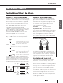
Signals — Level and Decibel
Assume the softest sound a human being can hear is at
a level of “1,” and the loudest sound a human being can
endure hearing is at a level of “1,000,000.” The
difference expressed in these numbers is huge, and
you have to use too many digits to express the level.
This is very inconvenient. So, we use a term or unit
called “decibel (dB),” defining the normal level
difference between the softest and loudest sounds
detectable by human hearing to be 120 dB.
A decibel is a relative value based on a reference level
of 0 dB. Audio devices usually treat audio as electrical
signals. There are various types of decibel
measurements: dBu, dBV, dBm, etc., but the most
popular one is dBu, which is based on 0.775V as the
reference level (0 dBu). The output level of a
microphone is very low –– about several millivolts (–60
dBu — –30 dBu). On the other hand, the maximum
output of a mixer can be 12 V (+24 dBu).
To create clear sounds, a signal should be input to a
mixer at an appropriate level. When you connect audio
devices to your mixer, be sure to match the nominal
input of an instrument to the output level of the mixer,
then adjust the input level with the mixer’s gain control.
Balanced or Unbalanced?
In most cases, shielded cables are used to transfer
signals between audio devices. Shielded cables are
divided into two types: balanced and unbalanced.
Balanced lines are very good at rejecting noise, and
they are the best choice for long cable runs or for
transferring very weak signals. Unbalanced cables are
usually used for line-level signals.
Microphone:
Use balanced lines.
Short line-level runs:
Unbalanced lines are fine.
Long line-level runs:
Use balanced lines.
We are constantly surrounded by random electromagnetic
radiation (noise), such as radio and TV signals as well as
spurious electromagnetic noise generated by power lines,
motors, electric appliances, computers, and other
sources. The longer the wire, the more noise it is likely to
pick up. To avoid noise, use the shortest cable possible.
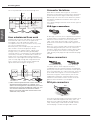
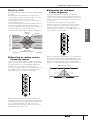
How balanced lines work
A cable that features an XLR plug on each end is a
balanced line. It consists of hot (+), cold (–), and
ground conductors.
A device transmits an original hot (+) signal through the
hot conductor and the same, but inverted, signal
through the cool (–) conductor to the destination. The
receiving device inverts the inverted signal back to
normal and combines it with the original hot signal.
Any noise induced in the line will be exactly the same in
both conductors, and thus in phase. The trick is that the
phase of one signal (through the cool (–) conductor) is
reversed at the receiving end of the line so that the
desired audio signals become in-phase, and the
induced noise suddenly finds itself out of phase. The
out-of-phase noise signal is effectively canceled while
the audio signal is left intact.
Recording Basics
+ 20 dBu
0 dBu
0.775 V
-
20 dBu
-
40 dBu
-
60 dBu
Professional audio gear, such as a
mixer or a power amplifier, features
line inputs and outputs with a
nominal level of +4 dBu.
Keyboards and other line instruments
have line inputs and outputs with a
nominal level of –10 dBu.
Microphone levels vary depending
on the sound source. Speech is at
about –30 dBu. Bird chirping is
lower than –50 dBu. Closely
recorded drums could reach 0 dBu.
input signal
gain
control
output signal
too high
appropriate
level
too low
Anatomy of a shielded cable
As shown in the illustration above, a shielded cable
consists of one hot (and cold conductor) wrapped in a
metal net (shield, or ground conductor). The ground
functions as a barrier against noise, protecting the
signal from noise that may be induced in the line.
hot
cold
shield
(ground)
jacket
balanced unbalanced

Recording Basics
Owner’s Manual
10
English
This is why balanced lines excel at rejecting noise.
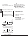
How unbalanced lines work
Unbalanced connectors and cables are less expensive
than balanced cables. If the level of signals to be
transmitted is very high and/or the signal is not
susceptible to noise, or all connections are very short,
you can use unbalanced lines.
Monaural phone jacks and RCA pin jacks (which are
often used for consumer AV gear) are always
unbalanced. On an unbalanced line, signals travel
through a hot (+) conductor and a ground (GND)
conductor (which is a combination of cold and ground
conductors). Therefore, an unbalanced line does not
feature noise canceling (unlike a balanced cable).
However, the output signal level through unbalanced
jacks is usually high enough that using unbalanced
lines is just fine. You can also convert unbalanced
signals into balanced signals using a DI
(*)
.
(*)
A DI is a direct injection box that converts unbalanced
signals into balanced signals. For example, if you
connect an electric guitar to a mixer directly, the sound
may be thin or noise may be induced. In this case, you
can connect a DI between the instrument and the
mixer to convert the signal into a balanced one and
avoid a thin, noisy sound.
Connector Variations
Audio devices feature various types of connectors.
Questions you are likely to encounter when setting up a
system for the first time might include “Why all these
different types of connectors on the back of my mixer?”
and “What is the difference between various types of
connectors?”
Let’s start by taking a look at the most common types of
connectors.
XLR-type connectors
An XLR-type connector, which supports balanced lines,
is sturdy and less susceptible to deformation. The plug
features a lock mechanism, so even if you pull the
cable, it will not be disconnected. It is often used in
professional environments that demand a high level of
reliability.
When you connect an XLR cable, the ground conductor
on the XLR plug and XLR jack comes in contact first.
Therefore, unlike with an RCA pin cable or phone cable,
you can avoid pop noises when connecting an XLR
cable. Usually, male plugs will output and female plugs
will input.
Phone connectors
The name “phone” arose simply because this
configuration was first used in telephone switchboards.
Phone jacks can be stereo or monaural. A stereo phone
jack is also referred to as a “TRS” phone jack, and is set
up to handle stereo signals, such as for headphones,
and insert I/O signals. A stereo phone jack can also
handle balanced signals. A monaural phone jack is
unbalanced, and can be used to connect an electric
guitar or other instruments, to an amplifier.
RCA pin connectors
This type of unbalanced pin jack has been widely used
on home audio/video equipment for many years. The
plugs are color coded according to the signals they
carry. A white plug is used for the left audio channel,
and a red plug is used for the right audio channel.
noise
hot (+)
cold (–)
ground
(GND)
transmitter cable receiver
noise canceling
phase
inversion
phase
inversion
synthesized
signal
noise
transmitter cable receiver
male female
stereo/TRS phone plug mono phone plug
white
red

Recording Basics
Owner’s Manual
11
English
Inside Your Mixer
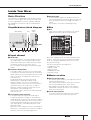
Basic Structure
The purpose of configuring an audio system around a
mixer is to collect signals from all channels and mix to
achieve a good balance. Here is a greatly simplified
block diagram of a mixer to help you understand the
signal path.
Simplified mixer block diagram
■ Input channel
1 Head amp
The very first stage in any mixer through which the
input signal flows. The head amp features a gain
control that enables you to adjust the mixer’s input
sensitivity to match the level of the source.
You can amplify small signals, and attenuate large
signals.
2 Compressor/Equalizer
This stage enables you to process the input signal.
A compressor attenuates the peak level of the input
signal, and raises the overall signal level at the same
time, to lessen the level difference and raise the
sound pressure.
An equalizer adjusts the tone by boosting
(amplifying) or cutting (attenuating) certain
frequency ranges. You can use an equalizer to
change the tone to suit the acoustic environment of
a particular room, or to create a new sound. An
equalizer could be a high pass filter that cuts the
sound below a specified frequency.
Some mixers feature compressors and/or equalizers,
and some do not.
3 Level meter (input channel)
If the signal level is too high for the head amp or
compressor/equalizer to handle, the sound will clip
and be distorted. An input channel level meter enables
you to monitor this signal level. Some mixers feature a
channel peak LED that indicates only the peak level.
If the input signal is overloaded, adjust the head
amp gain control.
Most mixers have multiple level meters (including the
indicators). It is important to know the mixer stage for
which the meters are indicating signal levels.
4 Channel fader
A channel fader enables you to adjust the level of
the corresponding input channel signal that is going
to be routed to the buses (excluding a pre-fader
signal).
This control is most often used during mixing.
■ Bus
5 Bus
Input channel signals are routed to buses, mixed
together there, then output in stereo (master).
Buses are categorized into a few types based on their
purpose: stereo bus for stereo mix, AUX bus for AUX
send, etc. Using the appropriate buses is one of the
keys to basic mixing.
The n8/n12 features the following buses:
• STEREO bus (L/R)
• AUX bus (L/R)
• REC bus (L/R)
• REVERB bus (L/R)
• SOLO bus (L/R)
■ Master section
6 Stereo (master) fader
The master section enables you to adjust the level of
signals routed from buses.
Use a stereo master fader to adjust the level of the
mixer’s main output from the stereo buses.
Depending on the design of the mixer, a fader is
provided for each bus so that you can adjust the
level of each bus output.
7 Level meter (master)
This meter indicates the signal level in the master
section, which is the mixer’s final output level.
IN
OUT
BUS
1 2 3 4 5 6 7
COMP
EQ
input channel bus
master
section
bus

Recording Basics
Owner’s Manual
12
English
Monitor mix for musicians,
external effects
One important mixer function is to send out signals for
signal processing via an external effect unit or to be
monitored by the musicians. For these purposes, mixers
feature AUX bus and Insert I/O.
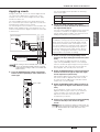
■ AUX buses for monitor sends
and overall effects
AUX (Auxiliary) buses are very convenient buses that
can be used for various purposes, such as: a) to create
a monitor mix that is separate from the main mix and
sent to the players for monitoring, and b) to process the
signal via an external effect unit and then bring it back
into the mix.
When you are using the AUX buses, you need to
consider whether you want a “pre-fader” signal (a signal
taken from a point before the channel fader) or a “post-
fader” signal (a signal taken from a point after the
channel fader) to be sent to the AUX buses.
On the n8/n12, a pre-fader signal is sent to the AUX
bus. Thus the bus signal is not affected by the channel
fader.
• Using AUX buses to create a monitor mix for players
Players prefer a pre-fader signal that maintains a proper
level balance. Since the pre-fader signal is sent to the
AUX bus on the n8/n12, even if you raise the input
channel fader for guitar during the guitar solo, the fader
operation does not affect the AUX bus output, which
remains independent of the main mix.
If a post-fader signal is routed to the AUX buses for
monitoring, the fader operation will affect the balance of
the monitor mix. This is something that you and the
players would probably like to avoid.
• Using AUX buses to process the signal via an
external effect unit
If you are using an AUX bus to send a pre-fader signal
to an external effect unit, you can adjust the level of the
input channel signal and the amount of effect
separately.
For example, if you operate the fader for the input
channel signal that is sent to the effect unit, the balance
between the dry signal (unprocessed) and the wet
signal (processed by the effect unit) will change. To
maintain the same balance between the dry and wet
signals, you must adjust the AUX send level whenever
you adjust the channel fader.
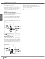
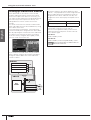
■ Insert I/O for processing
individual channel signals
Insert I/O jacks function in a manner similar to the AUX
buses: they provide a send and a return for signal
processing via an external effect unit. However, unlike
AUX buses that “collect multiple channel signals, then
send them together to an effect unit,” insert I/O jacks
are used to “send an individual channel signal to an
external effect unit, then return it to the mixer.”
A channel signal that is routed to the insert out jack has
already been amplified or attenuated to an appropriate
level via the gain control. Connect a compressor, limiter,
equalizer or other effect unit that can control the overall
signal to the insert I/O jacks.
You can also connect a reverb or similar effect unit to
process only a single channel signal.
When you connect an effect unit to the insert I/O jacks,
the channel signal will be routed to the external effect
unit via the insert out jack. The signal will be processed
by the effect unit, then returned to the mixer via the
insert in jack. It then resumes its normal path.
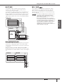
PRE
ON
OU
T
OU
T
AUX BUS
STEREO BUS
channel
fader
stereo fader
AUX send level
■ Built-in digital reverb
The n8/n12 features a REVERB bus that is dedicated
to the built-in digital reverb. This is almost identical to
the AUX bus, and can be used to send signals to the
built-in digital reverb.
The only difference from the AUX bus is that a post-
fader signal is routed to the REVERB bus. Therefore,
the send level is affected by the channel fader, so
the effect level always remains in proportion to the
channel signal when you adjust the channel fader.
POST
OUT
REVERB BUS
STEREO BUS
channel fader
stereo fader
REVERB
send level
digital
reverb
INSERT
OUT
INPUT CHANNEL
INSERT
IN
effect unit
channel
fader

Front and Rear Panels
Owner’s Manual
13
English
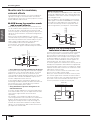
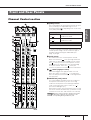
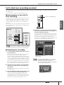
Channel Control section
1 [GAIN] control
This control adjusts the input signal level from the input
jacks (sensitivity). The adjustable range on each
monaural channel varies depending on the on/off status
of the [PAD] switch (
2
).
To achieve a quality sound with a good S/N ratio and
a wide dynamic range, set this control as high as
possible without allowing the OVER LED (see
page 15) to light.
2 [PAD] switch
This switch turns each channel pad on and off.
When it is turned on ( ), the input signal from the
input jacks is attenuated by 26 dB. Turn the switch
off ( ) when you connect a microphone or other
device with a low input level to the corresponding
monaural channel. Turn it on ( ) when you
connect a synthesizer or other line-level instruments.
3 switch (high pass filter)
This switch toggles the high pass filter on or off.
When the switch is turned on ( ), the high pass
filter cuts frequencies below 80 Hz of the signal from
the input jacks.
4 PHANTOM [+48V] switch
This switch toggles phantom power for condenser
microphones on and off. If you are connecting
condenser microphones to the XLR-type INPUT A
jacks on the rear panel, turn the switch on ( ).
(The switch LED lights up.)
Each phantom switch turns the phantom power on and
off for four channels simultaneously. (Channels 1-4 and
channels 5-8 on the n12, and channels 1-4 on the n8).
Front and Rear Panels
)
!
1
4
2
5
6
3
7
8
9
)
!
@
#
$
^
*
&
%
n12
Monaural input channel
[PAD] switch is
on ( ).
The level can be adjusted between
–34 dB and +10 dB.
[PAD] switch is
off ( ).
The level can be adjusted between
–60 dB and –16 dB.
Stereo input channel
The level can be adjusted between –26 dB and +4 dB.
When the switch is turned on, phantom power DC
+48V will be supplied to Pin 2 and Pin 3 of the
corresponding XLR-type INPUT A jacks.
NOTE

Front and Rear Panels
Owner’s Manual
14
English
5 [PHASE] switch
Turning this switch on ( ) inverts the phase of the
signal from the input jacks.
For more information on the [PHASE] switch, refer to
“Tip for compensating for the phase offset” on
page 15.
6 [Hi-Z] switch
If you are connecting an electric guitar or electric
bass that has passive-type pickups and no built-in
preamp directly to the INPUT B jack of input channel
8 (on the n12) or input channel 4 (on the n8), turn
this switch on ( ).
7 [INPUT SELECT] switch
This switch determines whether the input jack signal
(A.IN) or the DAW signal (the output from Cubase or
another DAW) will be routed to the input channels.
8 Compressor controls
These compressor controls enable you to operate the
compressor for each monaural input channel
(channels 1-4 on the n8, and channels 1-8 on the n12).
The following two controls are available for each
compressor: [MORPH] control and [DRIVE] control.
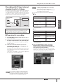
[MORPH] control
This control specifies the compressor setting. Knob
positions A-E correspond to different presets. You
can easily change the compressor setting by rotating
the control. Knob positions between alphabetical
settings will use an intermediate value taken from
between two corresponding preset values.
[DRIVE] control
This control specifies the amount of compression. As
you rotate the control clockwise, more compression
is applied. The output level changes automatically
as the amount of compression changes.
COMP LED
This LED lights up when the compressor is triggered.
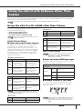
9 Equalizer (EQ)
This three-band equalizer adjusts the input channel’s
high, mid, and low frequency bands. You can also
adjust the center frequency for the mid band.
[HIGH] gain control
This control adjusts the high band gain.
[MID] frequency control
This control adjusts the mid band center frequency.
[MID] gain control
This control adjusts the mid band gain.
[LOW] gain control
This control adjusts the low band gain.
Setting each gain control knob to the “▼” position
produces a flat frequency response (no boost).
Turning the knob clockwise boosts the
corresponding frequency band, while turning
counter-clockwise attenuates the band.
To raise the mid band center frequency, turn the
[MID] frequency control clockwise. To lower the
center frequency, turn the [MID] frequency control
counter-clockwise. At the center position, the center
frequency is 1.0 kHz.
The following table shows the EQ type, center frequency,
and maximum cut/boost for each of the three bands.
) [REVERB] control
This control adjusts the level of the input channel
signal sent to the internal digital reverb (i.e.,
determines how much reverb will be applied).
When you set the knob to the “▼” position, the input
channel signal at the nominal level (0 dB) will be
sent to the internal digital reverb.
! [AUX] control
This control adjusts the level of the input channel
signal sent to the AUX bus. Use this control when
you are sending a mix monitoring signal to the
musicians, or sending the signal to an external
device, such as an effects processor.
@ [PAN] and [BAL] controls
[PAN] control
This control determines the stereo position of the
monaural input channel. Rotate the knob clockwise to
pan the signal right, and counter-clockwise to pan left.
[BAL] control
This control determines the volume balance between
the left and right stereo channels. Odd channel
signals are fed to the L bus, and even channel
signals are fed to the R bus. For example, rotate the
[BAL] control all the way to right to output only the
even (right) channel signals.
Caution
• Be sure to leave this switch off ( ) if you do not need
phantom power.
• When turning the switch on ( ), make sure that only
condenser microphones are connected to the INPUT A jacks.
Devices other than condenser microphones may be
damaged if they are connected to the phantom power supply.
Note, however, that the switch may be left on when you
connect balanced dynamic microphones.
• To avoid damage to your hearing or speakers, be sure to roll
off the volume level of the amplifier (or powered speakers)
before turning this switch on or off. Yamaha also
recommends that you turn all output controls, such as the
STEREO fader and [C-R PHONES LEVEL] control to
minimum settings before operating the switch.
Use an unbalanced cable when you connect an electric
guitar or bass and turn the [Hi-Z] switch on. If you use a
balanced cable, the mixer will not work correctly.
For more information on how to use the compressor,
please refer to page 28.
NOTE
NOTE
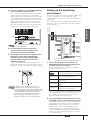
Band Type Center Frequency
Maximum
Cut/Boost
HIGH shelving 10 kHz ±18 dB
MID peaking 100 Hz – 10 kHz ±18 dB
LOW shelving 90 Hz ±18 dB
When the Channel Control [WET] switch is on,
signals via a DAW will be directly routed to the AUX
bus (Monitor Remote function). Therefore, the [AUX]
control will be temporarily disabled while the [WET]
switch is turned on.
NOTE

Front and Rear Panels
Owner’s Manual
15
English
# [SOLO] switch
This switch turns the Solo function on and off. Turn
this switch on (the switch LED lights up), if you want
to listen to certain channels without changing the
mix contents or signal path.
$ Channel [ON] switch
Switches each channel on and off. If you turn the
switch on, the channel signal will be sent to each
bus. When the switch is turned off (the switch
indicator turns off), the channel signal will be sent
only to the AUX bus.
% Channel fader
The channel fader adjusts the input channel signal
level. The fader at the “0” position corresponds to
the nominal output level. This means that the pre-
fader level and post-fader level are identical.
^ Input meter
The four LEDs indicate the input channel signal
level. When the input signal is clipping, the OVER
LED will light up.
You can check the level of the post-fader
signal via the input meter by setting the [INPUT
METER] switch (page 17) in the Meter section to
“POST.”
& [WET] switch
The Monitor Remote function can be used to select
whether or not the input channel monitor signal will
be processed via software effects. If you turn this
switch on (the LED lights up) while Cubase and the
mixer are linked and operating together, you can
monitor a wet signal (an input signal that has been
processed via the VST or other effects).
* [REC] switch and [ST] switch
These switches route the signal to the specified
buses. Turn the [ST] switch on (the LED lights up) to
route the channel signal to the stereo L/R buses.
Turn the [REC] switch on to route the channel signal
to the REC (L/R) buses.
If you switch the monitor source by using the [C-R
SOURCE SELECT] switch (page 18), all channel
[SOLO] switches will be reset to off.
Direct output to a connected computer is always
available regardless of the channel [ON] switch
status.
• While this switch is turned on, the [AUX] control
for the corresponding input channel will be
disabled.
• To use the Monitor Remote function, you must
turn on the MONITOR REMOTE [ON] switch
(page 19) (the switch LED will light up).
• This switch will work while the Cubase Direct
Monitoring function is turned off when both
devices Steinberg MR816 CSX/MR816 X and n8/
n12 are connected to a computer. You will not be
able to monitor the n8/n12 input signals while both
the Cubase Direct Monitoring function and the
[WET] switch are turned on.
NOTE
NOTE
Only
NOTE
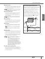
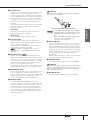
Tip for compensating for the phase offset
When you are recording a single instrument using
multiple microphones, the position and the distance
between the instrument and microphones may cause
the phase of each recorded signal to be offset
against each other (out of phase). If you try to mix
such signals, the signals will interfere with each
other, resulting in a thin sound.
For example if you record the sound of a guitar
amplifier by placing microphones in front of and
behind it in order to capture the resonance of the
cabinet, the microphone placed behind the amplifier
will pick up a signal with an offset phase. In this
case, turn the [PHASE] switch (
5
) on to avoid the
phase offset and interference.
phase
offset
phase of mic
signal from
behind
phase of mic
signal from in
front

Front and Rear Panels
Owner’s Manual
16
English
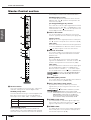
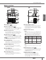
Master Control section
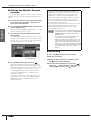
1 Reverb section
This section enables you to set the type, output level,
and other settings for the internal digital reverb.
REVERB [TYPE] switch
This switch determines the type of internal digital reverb.
Each press of the switch cycles through different
effect types in this order: HALL → ROOM → PLATE.
[REVERB TIME] control
This control adjusts the reverb time (duration of
reverberation) of the internal digital reverb. Rotating
the knob counter-clockwise will shorten the duration,
and rotating it clockwise will extend the duration.
REVERB [LEVEL] control
This control adjusts the output level of the internal
digital reverb. The “▼” position corresponds to the
nominal level (0 dB).
[TO AUX]/[TO REC]/[TO ST] switches
These switches route the output signal from the internal
digital reverb to the AUX, REC, or STEREO buses. Turn
the desired switch on ( ) to route the output from the
internal digital reverb to the desired buses.
2 2TR TO ST section
This section enables you to adjust the level of and
route the signal input from the 2TR IN jacks (page 20).
[LEVEL] control
Adjusts the level of the signal input from the 2TR IN jacks.
The “▼” position corresponds to the nominal level (0 dB).
[ON] switch
This switch determines whether the 2TR IN signal will be
sent to the STEREO buses. When the switch is turned on
( ), the 2TR IN signal is sent to the stereo buses.
3 DAW TO ST section
This section enables you to adjust the level of and
route the stereo signal transmitted from the DAW
(DAW IN 1/2).
[LEVEL] control
This control adjusts the level of the stereo DAW
signal to the STEREO buses. The knob set to the “▼”
position corresponds to the nominal level (0 dB).
[ON] switch
This switch determines whether the stereo output signal
from the DAW will be routed to the STEREO buses.
When the switch is turned on ( ), the stereo output
from the DAW will be sent to the mixer’s STEREO buses.
4 STEREO [BAL] control
This control adjusts the left and right volume balance
of the stereo channels (STEREO L/R).
5 [PFL] (Pre-Fader Listen) switch
If you want to monitor pre-fader input channel
signals when you are using the Solo function, turn
this switch on ( ).
6 STEREO [ON] switch
This switch turns on and off the signal output from
the ST OUT jacks. When the switch is on ( ), the
signal is output from the ST OUT jacks.
7 STEREO fader
This fader adjusts the level of the signal output from
the ST OUT jacks. The “0” position corresponds to
the nominal output level (0 dB).
HALL Simulates reverberation in a concert hall.
ROOM Simulates reverberation in a room.
PLATE Simulates reverberation of a plate echo.
1
2
3
4
5
6
7
If you turn on the C-R SOURCE SELECT
[5.1] switch, the DAW TO ST [ON] switch will be
disabled.
While this switch is turned on, if you also
turn the [SOLO] switch on, the monitor signal
volume may become very loud. In this case, use the
[SOLO LEVEL] control (page 17) to adjust the
monitoring volume level. The monitoring volume
level of the n8 is always attenuated by 12 dB.
NOTE
Only
NOTE
Only

Front and Rear Panels
Owner’s Manual
17
English
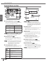
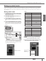
Meter section
1 Microphone
This is a built-in talkback microphone.
2 [SOLO LEVEL] control
This control adjusts the SOLO L/R bus output level. The
adjustable range is from –∞ to +6 dB. The “▼” position
corresponds to the nominal output level (0 dB).
3 [DAW TO AUX] control
This control adjusts the level of the signal routed
from the DAW AUX output (n12= DAW IN 15/16, n8=
DAW IN 11/12) to the AUX buses. The “▼” position
corresponds to the nominal output level (0 dB).
4 [AUX LEVEL] control
Adjusts the AUX OUT signal level (page 21). The “▼”
position corresponds to the nominal output level (0 dB).
5 AUX PHONES jack
This headphone connector outputs the AUX bus
signal. Use this connector to send a monitor signal
to the musicians. The output level at this jack can be
adjusted independently of the AUX OUT jacks.
6 [AUX PHONES] control
This control adjusts the output level at the AUX
PHONES jack. The “▼” position corresponds to the
nominal output level (0 dB).
7 C-R PHONES jack
This headphone jack outputs the control room
signal. The output level at this jack can be adjusted
independently from that of the C-R OUT jacks.
8 [C-R PHONES] control
This control adjusts the output level at the C-R
PHONES jack. The “▼” position corresponds to the
nominal output level (0 dB).
9 CUBASE READY indicator
This indicator lights up when the mixer is ready to be
operated with Cubase 4/Cubase Studio 4/Cubase
Essential 4/Cubase AI 4; that is, when the computer
is connected to the n8/n12 and Cubase is linked to
the mixer correctly.
) MASTER LEVEL METER
■ n12
This meter indicates the level of the STEREO/REC/AUX
bus signals, or the output level at the C-R OUT jack. To
switch the meter view, use the [METER SELECT] switch
(
!
). Depending on the setting of the [METER SELECT]
switch, the meter indication will change as follows:
* Surround channels are indicated in parentheses.
■ n8
This meter indicates the output level at the C-R OUT
jacks.
! [METER SELECT] switch
This switch determines which signal will be indicated
via the MASTER LEVEL METER. Pressing the switch
will toggle between C-R (C-R OUT jacks) and BUS
(STEREO/REC/AUX bus).
@ [INPUT METER] switch
This switch selects the signal whose level is
indicated on the input meter (page 15) in the
Channel Control section. Pressing the switch
repeatedly toggles between PRE (pre-fader) and
POST (post-fader).
n12 n8
2
@
1
4365
8
!
7
)
9
3 8
56 7
9
)
While you are using the Monitor Remote function
(page 33), signals that pass through the DAW will be
directly routed to the AUX bus.
Only
Only
Only
NOTE
[METER
SELECT]
switch
Meter A Meter B Meter C
C-R*
C-R OUT
jacks A
(L/R)
C-R OUT
jacks B
(C/SW)
C-R OUT
jacks C
(LS/RS)
BUS
STEREO
bus
REC bus AUX bus
Only
Only

Front and Rear Panels
Owner’s Manual
18
English
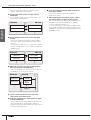
Control Room section
1 C-R SPEAKER SELECT switches
These switches select the jacks that will output the
control room monitor signal. When you turn on one of
the switches, the LED lights up, and the
corresponding jacks output the monitoring signal.
2 [DOWN MIX] switch
This switch converts 5.1-ch surround signals (input
from the DAW) into 2-ch L/R signals. While the
switch is on, converted 2-ch signals are output from
the C-R OUT jacks A.
3 C-R SOURCE SELECT switches
These switches enable you to select a monitoring source
(the signal output from the C-R OUT jacks). The
following switches and monitoring sources are available:
4 [DIMMER] switch
This switch turns on and off the Dimmer function that
temporarily lowers the monitoring volume. For
example, this can be convenient when you want to
have a conversation in the control room.
5 [MUTE] switch
This switch turns on and off the Mute function that
mutes the monitoring signal. Repeatedly pressing
the switch toggles between on (the switch will light
up) and off (the switch will turn off).
6 [CONTROL ROOM LEVEL] control
This control adjusts the monitoring volume in the
control room. Turning the knob clockwise will
increase the volume level.
7 TALKBACK [LEVEL] control
This control adjusts the input level of the built-in
microphone. The “▼” position corresponds to the
nominal level (0 dB).
8 [TALKBACK] switch
While this switch is being pressed, you can
communicate with the musicians (Talkback function).
When the Talkback function is turned on, the switch LED
will flash and the Dimmer function (
4
) will be enabled.
6
4
3
5
1
4
6
7
2
8
5
3
n12 n8
Switch Output jacks
C-R SPEAKER SELECT [A]
switch
C-R OUT jacks A (L/R)
C-R SPEAKER SELECT [B]
switch
C-R OUT jacks B (L/R)
C-R SPEAKER SELECT [C]
switch
C-R OUT jacks C (L/R)
While the C-R SOURCE SELECT (
3
) [5.1] switch is
turned on, you can use these switches to individually
turn the surround channels on and off. For more
information, please refer to page 47.
• In order to monitor in a surround environment, you will
need a surround-capable application such as Cubase 4.
The included Cubase AI 4 does not support surround.
• This switch is effective only while the C-R
SOURCE SELECT [5.1] switch is turned on.
[5.1] switch
Enables you to monitor the 5.1-ch surround
signal input from the DAW. (page 46)
[DAW]
switch
Enables you to monitor the DAW stereo
signal (DAW IN 1/2).
[ST] switch
Enables you to monitor the STEREO
bus signal.
[AUX]
switch
Enables you to monitor the AUX bus
signal.
[2TR]
switch
Enables you to monitor only the input
signal at the 2TR IN jacks.
Only
NOTE
Only
NOTE
Only
• In order to monitor in a surround
environment, you will need Cubase 4. The
included Cubase AI 4 does not support surround.
• You can turn on the [5.1] switch and [ST] switch
simultaneously. In this case, the 5.1-ch L/R signal
and STEREO bus L/R channel signals will be
mixed and output.
The talkback signal will be sent to the AUX outputs
(AUX PHONES jack and AUX OUT jacks).
NOTE
Only
Only
Only
NOTE

Front and Rear Panels
Owner’s Manual
19
English
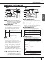
DAW Remote Control section
1 WORK MODE switches
These switches enable you to change the connection
status between the n8/n12 and Cubase all at once. The
following connection settings (Work modes) can be
selected depending on your needs. Pressing each
switch changes I/O settings and bus assignments.
2 MONITOR REMOTE [ON] switch
This switch turns on and off the Monitor Remote
function that enables you to process the input
channel and REC bus signals via the VST effects and
monitor them. When the switch is turned on (the
switch will light up), the input channel [WET] switches
(page 15), the MONITOR REMOTE [REC BUS WET]
switch (
3
), and other switches become available.
3 MONITOR REMOTE [REC BUS WET] switch
This button determines how to monitor the signals
that is being recorded via the REC bus with the
Monitor Remote function (page 33). When this switch
is on, you can monitor the REC bus signals that have
been processed within Cubase by VST effects, etc.
4 CLICK REMOTE [ON] switch
This switch remotely turns on and off the metronome
(click sound) in Cubase. If you turn the metronome
ON in Cubase, this switch will reflect the setting.
5 [CLICK LEVEL] control
This control adjusts the volume level of the Cubase
metronome (click sound). Turning the knob
clockwise will raise the volume, and turning the knob
counter-clockwise will lower the volume.
6 TRACK CONTROL switches
These switches remotely control Cubase tracks.
Each switch features the following function:
7 TRANSPORT switches
These switches remotely control the transport section
in Cubase. Each switch has the following function:
4
5
2
1
3
6
7
4
2
1
3
6
7
5
n12 n8
All switches in this section are enabled only when
the n8/n12 is connected to the computer via an
IEEE1394 cable and the mixer’s operation is linked
to Cubase 4/Cubase Studio 4/Cubase Essential 4/
Cubase AI 4. For more information on the Cubase
Link function, please refer to page 33.
ST MIX
Enables you to monitor on the n8/n12 the
stereo signal mixed in the Cubase mixer
and output from the DAW.
HARDWARE
MIX
Enables you to output Cubase audio
tracks individually to the n8/n12, then mix
them on the n8/n12.
5.1 MIX
Enables you to create a 5.1-ch
surround mix in Cubase 4.
For information on operations in each Work mode,
please refer to page 36.
• To use the Monitor Remote function, turn on the
MONITOR REMOTE [ON] switch (
2
) (the switch
LED will light up).
• To monitor an effect signal that has been
processed by the VST effects, you must turn on
the Record Enable button for the destination audio
track in Cubase.
NOTE
Only
NOTE
NOTE
[PREV ▲]
switch
Selects the previous track (the track
one above in the track list) in Cubase.
[NEXT ▼]
switch
Selects the next track (the track one
below in the track list) in Cubase.
[REC READY]
switch
Turns on and off the Record Enable
button for the track selected in Cubase.
[CYCLE] switch Turns Cycle mode on and off.
[] switch
Moves the current position to the
previous marker (or the beginning of
the project if there is no marker in the
backward direction).
[ADD] switch
Adds a marker at the current
position.
[] switch
Moves the current position to the
next marker.
[] switch Rewind
[] switch Fast forward
[■] switch Stops the project playback.
[] switch Plays the project.
[REC] switch
Records the track(s) whose
Record Enable button is on

Front and Rear Panels
Owner’s Manual
20
English
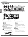
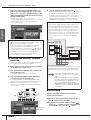
Rear I/O section
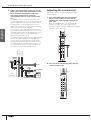
1 ANALOG INPUT jacks (monaural)
These monaural channel input jacks are used to connect
microphones or musical instruments. Each input channel
features two types of jacks (INPUT A and INPUT B).
INPUT A jacks
These are balanced XLR-type input jacks.
INPUT B jacks
These are balanced TRS phone-type input jacks that
also support unbalanced connections.
2 INSERT I/O jacks
These phone-type unbalanced I/O jacks are
positioned immediately before the A/D converter.
You can connect your effects processor or other
devices directly to these input channels.
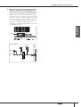
3 ANALOG INPUT jacks (stereo)
These are stereo input jacks that connect line-level
instruments, such as a synthesizer. Two jack types
are provided: phone type and RCA pin type.
Phone type
These are unbalanced stereo input jacks.
RCA pin type
These are unbalanced stereo input jacks.
Connect odd channels to the L jacks, and even
channels to the R jacks. If you connect only odd
channels to the phone-type jacks, the same signals
will be fed to the even channels, resulting in
monaural inputs.
4 2TR IN jacks
Use these unbalanced RCA pin jacks to input a
stereo sound source.
Use these jacks when you want to connect a CD or
other music source to the n8/n12 for monitoring.
You can adjust the level of signals input via these
jacks using the [2TR TO ST] control (page 16) in the
Master Control section.
9
!@ 7 6 5 2
8) 43 1
256@
98 ) 4 3 1
!
n12
n8
You may use either of these jacks, but you may not
use both at the same time. If you connect cables to
both jacks, INPUT B jack will take priority.
These are TRS phone jacks that support bidirectional
operation. Connection to an INSERT I/O jack
requires a special insertion cable as illustrated below.
Use a separately-sold Yamaha insertion cable
(YIC025/050/070).
NOTE
NOTE
To the INSERT I/O jack
sleeve
ring
tip
sleeve tip
To the output jack of
the external processor
To the input jack of the
external processor
If you connect cables to both phone type and RCA
pin type jacks, signals are mixed before the [GAIN]
control, then input to the corresponding channel.
NOTE
La page est en cours de chargement...
La page est en cours de chargement...
La page est en cours de chargement...
La page est en cours de chargement...
La page est en cours de chargement...
La page est en cours de chargement...
La page est en cours de chargement...
La page est en cours de chargement...
La page est en cours de chargement...
La page est en cours de chargement...
La page est en cours de chargement...
La page est en cours de chargement...
La page est en cours de chargement...
La page est en cours de chargement...
La page est en cours de chargement...
La page est en cours de chargement...
La page est en cours de chargement...
La page est en cours de chargement...
La page est en cours de chargement...
La page est en cours de chargement...
La page est en cours de chargement...
La page est en cours de chargement...
La page est en cours de chargement...
La page est en cours de chargement...
La page est en cours de chargement...
La page est en cours de chargement...
La page est en cours de chargement...
La page est en cours de chargement...
La page est en cours de chargement...
La page est en cours de chargement...
La page est en cours de chargement...
La page est en cours de chargement...
La page est en cours de chargement...
La page est en cours de chargement...
La page est en cours de chargement...
La page est en cours de chargement...
La page est en cours de chargement...
La page est en cours de chargement...
La page est en cours de chargement...
La page est en cours de chargement...
La page est en cours de chargement...
La page est en cours de chargement...
La page est en cours de chargement...
La page est en cours de chargement...
La page est en cours de chargement...
La page est en cours de chargement...
-
 1
1
-
 2
2
-
 3
3
-
 4
4
-
 5
5
-
 6
6
-
 7
7
-
 8
8
-
 9
9
-
 10
10
-
 11
11
-
 12
12
-
 13
13
-
 14
14
-
 15
15
-
 16
16
-
 17
17
-
 18
18
-
 19
19
-
 20
20
-
 21
21
-
 22
22
-
 23
23
-
 24
24
-
 25
25
-
 26
26
-
 27
27
-
 28
28
-
 29
29
-
 30
30
-
 31
31
-
 32
32
-
 33
33
-
 34
34
-
 35
35
-
 36
36
-
 37
37
-
 38
38
-
 39
39
-
 40
40
-
 41
41
-
 42
42
-
 43
43
-
 44
44
-
 45
45
-
 46
46
-
 47
47
-
 48
48
-
 49
49
-
 50
50
-
 51
51
-
 52
52
-
 53
53
-
 54
54
-
 55
55
-
 56
56
-
 57
57
-
 58
58
-
 59
59
-
 60
60
-
 61
61
-
 62
62
-
 63
63
-
 64
64
-
 65
65
-
 66
66


Yamaha n12 Le manuel du propriétaire
- Catégorie
- Matériel musical
- Taper
- Le manuel du propriétaire
- Ce manuel convient également à
dans d''autres langues
- italiano: Yamaha n12 Manuale del proprietario
- English: Yamaha n12 Owner's manual
- español: Yamaha n12 El manual del propietario
- Deutsch: Yamaha n12 Bedienungsanleitung
- русский: Yamaha n12 Инструкция по применению
- Nederlands: Yamaha n12 de handleiding
- português: Yamaha n12 Manual do proprietário
- dansk: Yamaha n12 Brugervejledning
- polski: Yamaha n12 Instrukcja obsługi
- čeština: Yamaha n12 Návod k obsluze
- svenska: Yamaha n12 Bruksanvisning
- Türkçe: Yamaha n12 El kitabı
- suomi: Yamaha n12 Omistajan opas
- română: Yamaha n12 Manualul proprietarului
Documents connexes
-
Yamaha n12 Manuel utilisateur
-
-
Yamaha n12 Guide d'installation
-
-
-
-
-
-
-
Yamaha MG2 Manuel utilisateur
Autres documents
-
Trust SPOTLIGHT Le manuel du propriétaire
-
Focusrite Platinum TwinTrak PRO Le manuel du propriétaire
-
 PYLE Audio PMX-1609 Manuel utilisateur
-
Optimus M-243 L Manuel utilisateur
-
TOA MA-725F Manuel utilisateur
-
Steinberg UR44C Startup Manual
-
-
-
Edirol AudioCapture UA-700 Le manuel du propriétaire
-
Marantz PMD-706 Mode d'emploi
