Sime Planet Dewy 30 Installation Instruction And Care Manual
- Taper
- Installation Instruction And Care Manual


Fonderie Sime S.p.A.
Via Garbo, 27 – 37045 LEGNAGO (VR)
declares that:
a) The materials used in the interior of the boiler are suitable for the use of drinking water.
b) No dangerous toxic substances were used to manufacture the boiler and its components, which could
enter the drinking water.
c) There is no contact zone between drinking water and the water used for the heating system.
déclare que:
a) Les matériels utilisés à l’intérieur de la chaudière sont idoines pour l’utilisation de l’eau potable.
b) Dans la fabrication de la chaudière et de ses composants aucune substance toxique dangereuse n’a
été utilisée qui pourrait s’infiltrer dans l’eau potable.
c) Il n’existe aucune zone de contact entre l’eau potable et l’eau du circuit de chauffage.
Date:
02/03/2009
CLAUDIO MEZZALIRA
Fonderie SIME Spa
Technical Manager

3
ENG
FR
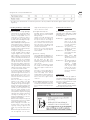
WARNING: If the information in this manual
is not followed exactly, a fire of explosion may
result causing property damage, personal
injury or loss of life.
• Do not store or use gasoline or other flam-
mable liquids or gases in the vicinity of this or
any other appliance.
• WHAT TO DO IF YOU SMELL GAS
• Do not try to light any appliances.
• Do not touch any electrical switches, do
not use any phone in your building.
• Immediately call your gas supplier from a
neighbour’s phone. Follow the gas sup-
plier’s instructions.
• If you cannot reach the gas supplier, call
the fire department.
• Installations and service must be performed
by a qualified installer, service agency or the
gas supplier.
Warning: Do not use this boiler if any part has been
under water. Immediately call a qualified service tech-
nician to inspect the boiler and to replace any part of
the control system and any gas control which has
been under water.
Warning: Should overheating occur, or the gas supply
fail to shut off, shut off the gas supply external to the
appliance. Do not switch off the electrical supply to
the pump.
Installation Instruction
and Care Guide
Planet Dewy 30/50 BF of Gas-Fired Wall Hung Hot Water Boilers
TABLE OF CONTENTS
1 DESCRIPTION OF THE BOILER 4
1.1 INTRODUCTION 4
1.2 DIMENSIONS 4
1.3 TECHNICAL FEATURES 5
1.4 FUNCTIONAL DIAGRAM 6
1.5 MAIN COMPONENTS 6
2 INSTALLATION 7
2.1 VENTILATION OF BOILER ROOM 7
2.2 BOILER SUPPORT BRACKET 7
2.3 CONNECTING UP SYSTEM 7
2.5 SYSTEM FILLING 8
2.6 FLUES/CHIMNEYS 8
2.8 POSITIONING OF OUTLET TERMINALS 11
2.9 ELECTRICAL CONNECTION 26
2.10 LOGICA REMOTE CONTROL 28
2.11 EXTERNAL TEMPERATURE SENSOR 30
3 CHARACTERISTICS 31
3.1 ELECTRONIC BOARD 31
3.2 TEMPERATURE SENSOR AND
WATER PRESSURE TRANSDUCER 32
3.3 ELECTRONIC IGNITION 32
3.4 FLOW SWITCH SAFETY VALVE 33
3.5 SMOKE STAT 33
3.6 SYSTEM AVAILABLE HEAD 33
3.7 MAINS ELECTRICITY CONNECTION 33
4 USE AND MAINTENANCE 35
4.1 GAS CONVERSION 35
4.2 GAS VALVE 35
4.3 CLEANING AND MAINTENANCE 36

4
ENG
FR
1.1 INTRODUCTION
“PLANET DEWY 30/50 BF” with stainless
steel hot water tank, boilers are premix con-
densation thermal appliances which use
microprocessor technology for function
control and management.
They comply with
ANSI Z21. 13 and CSA 4.9 GAS FIRED LOW
PRESSURE STEAM AND HOT WATER BOI-
LERS.
These appliances can be fired by both natu-
ral gas and Liquid Propane Gas.
The instructions given in this manual are
provided to ensure proper installation and
perfect operation of the appliance.
1 DESCRIPTION OF THE BOILER
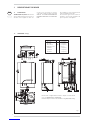
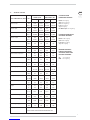
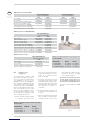
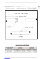
1.2 DIMENSIONS : mm (in)
PVC/CPVC
Fig. 1
Dimension Units Type 30/50 BF
R C.H. return C 3/4” (19 mm)
M C.H. supply C 3/4” (19 mm)
G Gas connection MNPT 3/4” (19 mm)
S3 Condensation outlet ø 25 (1 in.)
E D.H.W. inlet C 1/2” (13 mm)
U D.H.W. outlet C 1/2” (13 mm)
C Ricirculation C 1/2” (13 mm)
N.B.: The boiler is supplied with an aluminum adapter from diameter 80
mm to 3” SCHEDULE 40 (code 6249551).
Install this adapter for direct vent installations using PVC/CPVC venting.

5
ENG
FR
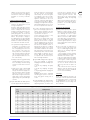
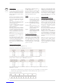
1.3 TECHNICAL FEATURES
CLEARANCES FROM
COMBUSTIBLE MATERIALS:
Bottom: 0 mm (0 in.)
Sides: 10 mm (0.4 in.)
Vent: 10 mm (0.4 in.)
Front: 0 mm (0 in.)
Top: 0 mm (0 in.)
Hot Water Pipes: 10 mm (0.4 in.)
CLEARANCES FROM SERVICE
AND PROPER OPERATION:
Bottom: 150 mm (6 in.)
Sides: 150 mm (6 in.)
Front: 600 mm (24 in.)
Top: 150 mm (6 in.)
MINIMUM CLEARANCES
FROM ELECTRIC METERS,
GAS METERS, REGULATORS
AND RELIEF EQUIPMENT :
US: 4 feet (1.22 m)
CND: 6 feet (1.8 m)
0-2000 ft/PD 2000-4500 ft/PD
Model PLANET DEWY 30/50 BF
Units
Natural gas Propane Natural gas Propane
Maximum input kW 32.24 32.24 29.31 29.31
But/h 110,000 110,000 100,000 100,000
Minimum input kW 8.8 8.8 8.8 8.8
But/h 30,000 30,000 30,000 30,000
Maximum output kW 29.5 29.5 26.8 26.8
But/h 100,800 100,800 91,600 91,600
Minimum output kW 8.0 8.0 8.0 8.0
But/h 27,300 27,300 27,300 27,300
Water content l 6.0 6.0 6.0 6.0
USgal 1.32 1.32 13.2 1.32
Electric Power consumption W 160 160 160 160
Maximum C.H. pressure bar 3,1 3,1 3,1 3,1
psi 45.0 45.0 45.0 45.0
Maximum C.H. temperature °C 85 85 85 85
°F 185 185 185 185
Expansion vessel Water content l 10 10 10 10
USgal 2.2 2.2 2.2 2.2
Expansion vessel Pre-charged bar 1 1 1 1
psi 14.5 14.5 14.5 14.5
C.H. setting range °C 10-80 10-80 10-80 10-80
°F 50-176 50-176 50-176 50-176
Hot water tank contents l 42 42 42 42
USgal 9.3 9.3 9.3 9.3
Quantity and temper. of hot water °C/l 622.5 622.5 622.5 622.5
°C/USgal 136.9 136.9 136.9 136.9
Maximum D.H.W. pressure bar 8.6 8.6 8.6 8.6
psi 12 5 125 125 12 5
Weight kg 70 70 70 70
lb 154 154 154 154
Orifice ø mm 6.9 4.6 6.9 4.6
inches 0,271 0,181 0,271 0,181
Maximum manifold gas pressure mbar 6.5 7.5 6.5 7.5
“W.C. 2.61 3.01 2.61 3.01
Minimum manifold gas pressure mbar 0.65 0.70 0.65 0.70
“W.C. 0,261 0,281 0,261 0,281
Minimum gas supply pressure mbar 8.7 19.9 8.7 19.9
“W.C. 3.5 7.99 3.5 7.99
Category IV
FOR EITHER DIRECT VENT INSTALLATION OR FOR
INSTALLATION USING INDOOR COMBUSTION AIR

6
ENG
FR
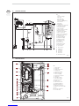
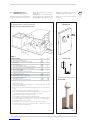
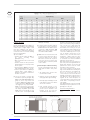
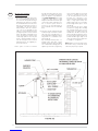
1.5 MAIN COMPONENTS
Fig. 3
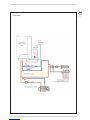
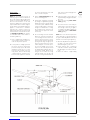
1.4 FUNCTIONAL DIAGRAM
Fig. 2
KEY
1 Fan
3 Primary exchanger
4 Gas valve
5 Hot water tank
6 C.H. sensor (SM)
7 Safety stat 100°C (212°F)
8 Air relief valve
9 C.H. pump
10 D.H.W. pump
11 Expansion vessel system C.H.
12 Hot water safety valve
13 Safety valve system
14 Boiler discharge
15 Water pressure transducer
16 Automatic by-pass
17 Expansion vessel D.H.W.
18 Gas cock (optional)
19 C.H. return cock (optional)
20 C.H. flow cock (optional)
21 D.H.W. inlet cock
22 Cock discharge tank
23 D.H.W. sensor (SB)
25 Magnesium anode
26 Fixing jig (optional)
27 Filling cock
28 No return valve
29 Condensation outlet
30 Flow switch water
31 Air relief valve
G Gas connection
U D.H.W. outlet
E D.H.W. inlet
C Ricirculation
M C.H. supply
R C.H. return
S3 Condensation outlet
31
1
3
4
18 19 20
13
27
21
22
23
12
25
29
7630
15 11
28
10
17
28
9
16
14
5
KEY
1 Control panel
2 C.H. pump
3 Condensation outlet
4 D.H.W. pump
5 Air pressure switch
6 Water flow meter
7 C.H. sensor (SM)
8 Air pressure test point
9 Safety stat
10 Sensing electrode
11 Primary exchanger
12 Ignition electrode
13 Smoke stat
14 Automatic breather
15 D.H.W. tank 42 liters
16 Ignition transformer
17 Hot water safety valve
18
Expansion vessel system C.H.
19 Fan
20 Pressure transducer
21
No return valve

The installation must conform to the requi-
rements of the Authority having jurisdiction
or, in the absence of such requirement, to
the National Fuel Gas Code, ANSI
Z223.1/NFPA 54 or CAN/CSA B149.1
natural gas and propane Installation Code.
Where required by the Authority having
jurisdiction, the installation must conform
to the Standard for Controls and Safety
Devices for Automatically Fired Boilers,
ANSI/ASME CSD-1.
All boilers must be installed with a proper
pressure relief valve.
Pressure relief valves must be installed to
conform to ANSI/ASME Boiler and Pressu-
re Vessel Code, Section IV, or CSA B51, as
applicable.
This boiler is equiped with a pressure tran-
sducer that cuts-off power to the ignition
sequence if the pressure of the heating cir-
cuit water falls below 0.7bar (10.2psi). For
boilers that are installed above the radia-
tion level, inquire with Authority having juri-
sdiction for additional requirements for low
water cut-off devices at the time of installa-
tion.
The boiler must be installed in a fixed loca-
tion and only by a qualified installer, service
agency or the gas supplier and is familiar
with the requirements that are contained
in this manual.
The boiler must not be installed on carpe-
ting.
The boiler when used in connection with a
refrigeration system, must be installed so
the chilled medium is piped in parallel with
the boiler with appropriate valves to pre-
vent the chilled medium from entering the
boiler.
The boiler piping system of a hot water boi-
ler connected to heating coils located in air
handling units where they may be exposed
to refrigerated air circulation must be
equipped with flow control valves or other
automatic means to prevent gravity circula-
tion of the boiler water during the cooling
cycle.
Service instructions and recommended fre-
quency guidelines periodic examination of
venting systems every six months.
Venting systems, the vent-air intake
system, screens in the vent terminal
should be checked and cleaned every six
months.
Low water cutoff should be checked and
cleaned every six months.
Remove small cover retaining screw and
remove the cover.
When the pump is running and water is
flowing around the boiler , the actuator lifts
off the micro switch.
Check that the operation of the actuator ;
Ensure that it is free and that it lifts and
returns.
If necessary lubricate the pivot point of
the actuator.
Flue gas passageways should be checked
and cleaning every six months.
Condensate collection and disposal system
should be checked and re-sealed every six
months.
The burner should be checked and cleaned
every six months.
Inspect the burner and if necessary clean
using a soft brush and a vacuum cleaner,
taking care not to damage the front insu-
lation.
Check the ignition /ionisation electrode,
check the ignition spark gap (4 mm +/-
0.5 mm) (0.16 in. +/- 0.02 in.).
Check the ionisation electrode, check the
distance from the burner (18.7 mm +/- 1
mm) (0.74 in. +/- 0.04 in). Before reas-
sembly inspect all seals and replace as
required.
Furthermore, the installation must be in
accordance with current standards and
regulations.
2.1 VENTILATION OF BOILER ROOM
When using air from the boiler room, an
adequate air supply shall by provided for
combustion of this boiler.
An insufficient supply can result in poor
combustion and possible sooting of the
burner, combustion chamber or flue pas-
sageway.
The boilers installed using inside air supply
must provide provisions for Combustion Air
and Ventilation Air in accordance with sec-
tion 5.3, Air for Combustion and Ventilation,
of the National Fuel Gas Code, ANSI Z
223,1/NFPA 54, or section 7,2, 7.3, or 7.4,
of CAN/CSA B 149, Installation Codes, or
local codes having jurisdiction.
Where an exhaust fan or any other air con-
suming appliance is installed in the same
space as the boiler, sufficient air openings
must be available to provide fresh air when
all appliance are operating simultaneously.
It is essential that in rooms where the boi-
ler are installed at least as much air can
arrive as required by normal combustion of
the gas consumed by the varius appliances.
Consequently, it is necessary to make ope-
nings in the walls for the air inlet into the
rooms.
These openings must meet the following
requirements:
1. Have a total free section of a least
2225 mm2 every kW (1 in2for every
1000 Btu/hr) of heat input, with a
minimum of 100 cm2(15.5 in2);
2. Where required by jursdiction or
when required for additional opening
must be provided at the highest ele-
vation practical.
With a hermetically sealed combustion
chamber and air supply circuit from out-
doors, may be installed in any room in the
home.
Keep boiler area clear and free from com-
bustible materials, gasoline and other flam-
mable vapors and liquids.
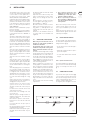
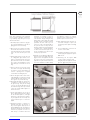
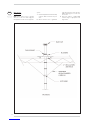
2.2 BOILER SUPPORT BRACKET
For the mounting of the support bracket of
the boiler, which is supplied, observe the fol-
lowing instructions (fig. 4):
– Fix the bracket to the wall with appro-
priate dowels.
– Check with a spirit level that it is perfec-
tly in horizontal plane.
– To fix the boiler with the lives evidenced
in figure.
2.2.1 System connection unions
The follow is available to facilitate water and
gas connection of the boiler with the heating
system: for assembly of the unions to see
fig. 1.
2.3 CONNECTING UP SYSTEM
To protect the heat system from damaging
corrosion, flakes or deposits, before instal-
lation it is extremely important to clean the
system using suitable products such as,
descaler or slug removing solution.
For long-term protection against corrosion
2 INSTALLATION
7
ENG
FR
Fig. 4

8
ENG
FR
and deposits, the use of inhibitors is recom-
mended after cleaning the system.
It is important to check the concentration
of the inhibitor after each system modifica-
tion and during maintenance following the
manufacturer’s instructions (specific tests
are available at your dealer).
The safety valve drain must be connected
to a collection funnel to collect any dischar-
ge during interventions.
If the heating system is on a higher floor
than the boiler, install the on/off taps sup-
plied in kit on the heating system
delivery/return pipes.
WARNING: Failure to clean the heat
system or add an adequate inhibitor inva-
lidates the device’s warranty.
2.3.1 Gas Requirements
Read the data plate to be sure the boiler is
made for the type of gas being used.
An adhesive data plate is inside the front
panel, it contains all the technical data iden-
tifying the boiler and the type of gas for
which the boiler is arranged.
If the information does not agree with the
type of gas available, do not install or opera-
te the boiler. Call your dealer.
The gas piping must be installed according
to all local and state codes, or in absence of
local and state codes, with the latest
“Natural gas and propane installation code”,
CAN/CSA-B 149.1 or “National Fuel Gas
Code”, ANSI Z223.1 (NFPA 54).
Consult the “Natural gas and propane
installation code” or “National Fuel Gas
Code” for the recommended gas pipe size
of other materials.
The sections of the piping making up the
system must be such as to guarantee a
supply of gas sufficient to cover the maxi-
mum demand, limiting pressure loss
between the gas meter and any apparatus
being used to not greater than:
1. 1.2 mbar (0.5”W.C.) for supply pressu-
res under 17 mbar (7”W.C.);
2. 2.5 mbar (1.0”W.C.) for supply pressu-
res from 17 mbar (7”W.C.) to 35 mbar
(14”W.C.).
Gas connections must be made in accor-
dance with current standards and regula-
tions.
When a vertical section of piping is instal-
led up stream/side of the boiler, install a
sediment trap at the inlet of boiler, that a
sediment trap must be provided upstream
of the gas control.
When dimensioning gas pipes from the
meter to the boiler, both capacity volume
(consumption) in m3/hr (ft3/hr) and gas
density must be taken into account.
The boiler and the boilers gas connection
must be leak tested before it is put in to
operation.
The boiler and its individual shut-off valve
must be disconnected from the gas supply
piping system during pressure testing of
the system at pressures in excess of 1/2
psi (3.5 kPa).
The boiler must be isolated from the gas
supply piping system by closing its individual
manual shut off valve during any pressure
testing of the supply piping system at test
pressures equal to or less than 1/2 psi
(3.5 kPa).
The boiler shall be installed such that the
gas ignition system components are pro-
tected from water (dripping, spraying, rain
etc.) during boiler operation or service (cir-
culators or control replacement etc.).
The boiler and its gas connection must be
leak tested before placing the the boiler is
put into operation.
Use a chloride-free soap and water solution
(bubbles forming indicate a leak) or other
approved method.
After placing the boiler in operation, the
ignition system safety shutoff device must
be tested. To testing the system :
- close the gas valve (gas cock)
- to feed the boiler
- to verify the ignition of the led “Ignition
lock”
- to open the gas cock and to unblock
“Reset”.
2.3.2 Condensation drain installation
A siphoned drain must be connected to the
civil drain by a pipe with minimum 6 mm
(1/4 in) for every 300 mm (1 foot) per
meter gradient for condensation collection.
Only normal plastic civil drain pipes are
suitable to convey condensation to the
building's sewer drain.
2.3.3 Gas pipe filter
The gas valve has a standard input filter
which, in any case, is not capable of filtering
all the impurities contained in the gas and
mains piping.
To prevent poor valve operations or in cer-
tain cases, excluding the valve's safety fea-
tures, we recommend installing a suitable
filter on the gas pipe.
2.5 SYSTEM FILLING
Filling of the boiler and the systemis done by
installing a pressure reducing valve. The
charge pressure, with the system cold,
must be between 1 and 1.2 bar (14.5 and
17.4 psi).
Filling must be done slowly so as to allow
any air bubbles to be bled off through the air
valves. Should the pressure have risen well
above the limit expected, discharge the over
pressure by opening the pressure-relief
valve. Bleed pump by loosen plug at back of
motor.
Once air is removed re-tighten plug. It may
be necessary to free the pump motor
before filling the system. This is done by
removing the pump plug and turning the
pump shaft loose. Do not forget to re-tight-
en pump plug before filling system.
To see following page about “Typical piping”.
2.6 FLUES/CHIMNEYS
The flue or chimney used to release the
products of combustion into the atmosphe-
re must comply with current standards
and regulations. Horizontal vent lengths
must be supported every I meter (39 in) or
less to prevent sagging.
The boiler can be exhausted using separate
pipe or forced draft. Follow the appropria-
te instructions below for your particular
venting configuration.
2.6.1 Installation separate pipes
(fig. 5)
The vent pipe must be certified ø 3” (76
mm) category IV venting; for this type of
flues it is necessary to demand kit optional
code 8089925 for tubes 3” in steel
(AL294C), and the kit code 8089926 for
tubes 3” in PVC or CPVC (standard with
units). When installing the pipes, follow clo-
sely the requirements of the current stan-
dards and regulations, as well as the fol-
lowing practical pointers:
1. With direct intake from outside, when
the pipe is longer than 1 m (3.28 ft -40
in), you are recommended to insulate
the piping so as to prevent formation of
dew on the outside of the piping during
particularly hard periods of the year.
2. With the outlet pipe outside the building
or in cold indoor environments, insula-
tion is necessary to prevent burner fai-
lure during trial for ignition.
In such cases, provide for a condensate-
collector system on the piping.
3. If a segment of the flue passes through
a flammable wall, this segment must be
insulated with a glass wool pipe insula-
tor 30 mm (1 in) thick, with a density of
50 kg/m3(3lb/ft3) or follow vent
manufacturers instructions for clearan-
ces to combustibles
4. The distance between the intake air and
the vent pipe must be within 6” (fig.
5/c).
5. Slope the venting towards the wall hung
boiler, for long runs or installation where
condensation in vent may cause flame
failure during trial for ignition provide a
condensation collection on the piping,
close to the wall hung boiler.
The maximum overall length of the intake
and exhaust ducts depends on the head
losses of the single fittings installed and
must not be greater than 5 mm H2O
(0.20 “W.C.).
For head losses in the fittings, refer to Table 2
- 2/a.


10
ENG
FR
TABLE 2/a (Accesories STAINLESS STEEL)
VENT ACCESSORIES Ø 3”
Load loss mm H2O (“W.C.)
Intake Outlet
90° curve MF 0.20 (0.00787) 0.20 (0.00787)
Extension L. 610 mm (2 ft) 0.10 (0.0394) 0.10 (0.0394)
Extension L. 914 mm (3 ft) 0.15 (0.00591) 0.15 (0.00591)
Extension L. 1520 mm (5 ft) 0.20 (0.00787) 0.20 (0.00787)
Terminal 1 (Termination Box : 2SVSRTF) -- 0.8 (0.0315)
Terminal 2 (Termination Hood : 2SVSHTX) -- 0.6 (0.0236)
Adapter from diam. 80 mm stell to 3” plastic SCH..40
0.05 (0.00197)
0.05 (0.00197)
Adapter from diameter 3” plastic to 3” steel
SCH.40 0.05 (0.00197) 0.05 (0.00197)
Adapter from diameter 4” plastic to 3” plastic
SCH.40 0.05 (0.00197) 0.05 (0.00197)
Adapter from diameter 3” plastic to 4” plastic
SCH.40 0.05 (0.00197) 0.05 (0.00197)
TABLE 2/b (Accessories PP)
VENT ACCESSORIES Ø 80
Load loss mm H2O (“W.C.)
Intake
90° curve MF 0.30 (0.0118)
45° curve MF 0.20 (0.00787)
Extension L. 1000 mm horizontal (3.3 ft) 0.20 (0.00787)
Extension L. 1000 mm vertical (3.3 ft) 0.30 (0.0118)
TABLE 2 (Accessories PVC or CPVC)
VENT ACCESSORIES Ø 3” VENT ACCESSORIES Ø 4”
Load loss mm H2O (“W.C.) Load loss mm H2O (“W.C.)
Intake Outlet Intake Outlet
45° curve MF 0.20 (0.00787) 0.20 (0.00787) 0.05 (0.00197) 0.10 (0.0394)
90° curve MF 0.30 (0.0118) 0.35 (0.0138) 0.10 (0.0394) 0.10 (0.0394)
Extension horizontal L. 1500 mm (5 ft) 0.50 (0.0197) 0.75 (0.0295) 0.20 (0.00787) 0.20 (0.00787)
Extension vertical L. 1500 mm (5 ft) 0.10 (0.0394) 0.10 (0.0394) 0.05 (0.00197) 0.05 (0.00197)
Terminal 1 (Termination box : 2SVSRTF) -- 2.50 (0.0984) -- 2.50 (0.0984)
Terminal 2 (Termination hood : 2SVSHTX) -- 1.30 (0.0512) -- 1.30 (0.0512)
Terminal 3 (Termination roof : System 636) -- 1.30 (0.0512) -- --
Maximum horizontal length for separate pipes with
a curve with 90°:
ACCESSORIES INTAKE OUTLET
ø 3” (PVC/CPVC) 15 m (49 ft) 15 m (49 ft)
ø 4” PVC/CPVC) 25 m (82 ft) 25 m (82 ft)
ø 3” (STAINLESS STEEL) 15 m (49 ft) 15 m (49 ft)
2.6.2 Installation forced
draft (fig. 5/a)
The vent pipe must be certified ø 3” (76
mm) category IV venting; for this type of
flues it is necessary to demand kit optional
code 8089925 for tubes 3” in steel
(AL294C), and the kit code 8089926 for
tubes 3” in PVC or CPVC (standards with
units). In addition, it is necessary to demand
air inlet terminal ø 80mm code 8089500.
Before proceeding with this venting configu-
ration, ensure that the requires of section
2.1 are met. When installing the exhaust
pipe, follow closely the requirements of the
current standards and regulations, as well
as the following practical pointers:
1. With the outlet pipe outside the building
or in cold indoor environments, insula-
tion is necessary to prevent burner failu-
re during trial for ignition. In such cases,
provide for a condensate-collector
system on the piping.
2. If a segment of the flue passes through
a flammable wall, this segment must be
insulated with a glass wool pipe insulator
30 mm (1 in) thick, with a density of 50
kg/m3(3lb/ft3) or follow vent manufac-
turers instructions for clearances to
combustibles
3. The distance between the intake air and
the vent pipe must be within 300 mm (1
ft - 12 in).
4. Slope the venting towards the wall hung
boiler, for long runs or installation where
condensation in vent may cause flame
failure during trial for ignition provide a
condensation collection on the piping,
close to the wall hung boiler.
The maximum overall length of the exhau-
st ducts depends on the head losses of
the single fittings installed and must not
be greater than 5 mm H2O (0.20 “W.C.).
For head losses in the fittings, refer to Table
2 - 2/a.
Maximum horizontal length for forced draft with a
curve with 90°:
ACCESSORIES ELBOWS OUTLET
ø 3” (
PVC/
CPVC) 1 21 m (68 ft)
ø 3” (
PVC/
CPVC) 2 20 m (65 ft)
ø 3” (
PVC/
CPVC) 4 18 m (59 ft)
Fig. 5
Fig. 5/a

11
ENG
FR
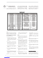
2.8 POSITIONING OF OUTLET
TERMINALS (figg. 5/b - 5/c)
The outlet terminal must be flush with the
wall and the inlet terminal must protrude
50 mm (2 in) at least from the outstide
wall (fig. 5/c).
Outlet terminals for forced draft systems
may be located on the outer walls of the
buildings. Table 1 shows approximate, non-
binding minimum distances to be met for a
building of the type shown in fig. 5/b.
Please refer to local codes for minimum
clearances.
MINIMUM DISTANCE mm feet
A - below openable window or door 900 3
B - below ventilation opening (non mechanical) 900 3
C - below eaves 300 1
D - below balcony (1) 300 1
E - from adjacent window or door 900 3
F - from adjacent ventilation opening (non mechanical) 900 3
G - from horizontal or vertical soil or drain pipes (2) 300 1
H - from corner of building 300 1
I - from recess in building 300 1
L-
above a paved sidwalk or a paved driveway that is
located on private property
2100 7
M - between two terminals set vertically 600 2
N - between two terminals set horizontally 600 2
O - from a surface facing without
openings or terminals 2000 6.56
P - as above but with openings and terminals 3000 9.84
The vent shall not terminate;
a) directly above a sidewalk or paved driveway that is located between two single - family dwel-
lings and severs both dwellings;
b) less that 2.1 m (7 ft) above a paved sidewalk or a paved driveway that is located on public pro-
perty;
c) within 1.8 m (6 ft) of a mechanical air-supply inlet to any building;
d) above a meter and regulator assembly within 1.8 m (6 ft) horizontally of the vertical centerline
of the regulator vent outlet to a maximum vertical distance of 4.5 m (15 ft);
e) within 1.8 m (6 ft) of any gas service regulator vent outlet;
f) less than 300 mm (1ft) above grade level plus expected snow level;
g) within 900 mm (3 ft) of a window or door that can be opened in any building, of any non-
mechanical air supply inlet to any building, or of any combustion air inlet of any other appliance;
h) Underneath a veranda, porch, or deck unless;
i) the veranda, porch, or deck is fully open on a minimum of two sides beneath the floor;
ii) the distance between the top of the vent termination and the underside of the veranda,
porch, or deck is greater that 300 mm (1ft).
TABLE 1
Fig. 5/b
To install the tubes in such way protect the
building materials from degradation by fluegas.
Fig. 5/c
Slanted view
Frontal view
System 636

12
ENG
FR
System 636 PVC or CPVC Type BH Gas
Venting Systems are third party certified to
ULC S636.
The following installation methods have
been prepared in conformity with the requi-
rements of section 4 of ULC Standard
S636.
1. Application
IPEX System 636 PVC or CPVC Gas Venting
Systems are intended for negative or positi-
ve pressure venting of gas fired appliances
producing exhaust gases having temperatu-
res limited to the range specified in 1(a) and
1(b).
(a) System 636 CPVC venting systems are
suitable for temperatures up to and inclu-
ding 90°C (194°F); ULC S636 Class II.
(b) System 636 PVC venting systems are
suitable for temperatures up to and inclu-
ding 65°C (1
49
°F); ULC S636 Class II.
2. Limiting to Use and Application
(a) Improper installation of System 636
PVC/CPVC systems may result in per-
sonal injury or death.
Only qualified personnel should attempt
the installation of gas burning equip-
ment, following the gas appliance manu-
factures' directions.
(b) All System 636 gas venting pipe and fit-
ting must be carefully inspected before
use to ensure no damage has occurred
during transportation.
Any damaged product must be repla-
ced.
No attempt at repairs shall be made at
the job site.
(c) The common temperature changes in a
gas venting application will cause the
system to expand and contract accor-
dingly, proper care must be taken to
allow for this movement through walls,
ceilings, and roof penetrations.
The venting system must be supported
in accordance with these instructions.
(d) Only approved System 636 PVC or
CPVC primer and cement shall be used
to assemble System 636 PVC or CPVC
venting systems respectively.
* All IPEX System 636 cements contain
an optical brightener to aid in identifi-
cation during warranty claims.
Note: Follow IPEX solvent cementing proce-
dures as shown in this manual, and check
for proper joint construction when joining
pipe to fittings.
System 636 Pipe, Fittings and Cements
are certified as a system and must be
installed as such.
Different manufacturers have different
materials, joining systems and adhesives.
Do NOT mix pipe, fittings, solvents, or joi-
ning methods from different BH Vent
manufacturers, this can result in unsafe
conditions.
(e) Venting should be as direct as possible
with a minimum number of fittings.
The maximum vertical rise or horizontal
run of vent pipe in a single vent installa-
tion shall not exceed the requirements
outlined in the appliance manufacturer's
installation instructions.
The total number of vent fittings in a sin-
gle vent installation shall not exceed the
requirements outlined in the appliance
manufacturer's installation instructions.
(f) All framing requirements for floor and
ceiling penetrations shall be in accor-
dance with the local building code
and/or the local regulatory authority.
(g) All penetrations of fire rated floors
and/or walls shall be as required by the
local building code and/or the local
regulatory authority.
All fire stopping of venting shall be com-
pleted using fire stops that are listed by
a recognized agency.
Fire stop installation shall be as per the
fire stop device / system manufactu-
rer's installation instructions.
(h) Roof penetrations should be sealed with
a plumbing roof boot or equivalent fla-
shing as per the local building code, or
as permitted by the local regulatory
authority.
(i) All framing required in conjunction with
wall and roof terminations shall be in
accordance with the local building code
and/or the local regulatory authority.
(j) WARNING: Insulation shall not interfere
with required clearance spaces.
4. Special System Layout Considerations
(a) Vent piping must be sized according to
the equipment manufacturers' recom-
mendations.
IPEX does not recommend the use of
existing vent piping, flues or chimneys.
When old appliances are replaced, do
not connect System 636 venting to exi-
sting vent materials.
Replace the entire existing venting
system with ULC S636 listed venting
material. If transitions between ABS,
PVC or CPVC must be made at the
appliance, only System 636 PVC/ABS
or CPVC/ABS Transition Cement shall
be used. System 636 Primer may only
be used on PVC or CPVC connections.
Do not use Primer on ABS appliance
connections.
(b) All horizontal sections of the venting
system must be installed with a slope
not less than 0,8 inch (20 mm) per 40
inches (1000 mm) down towards the
2.8.1 Installation Methods for IPEX System 636 Type BH PVC or CPVC Gas Venting Systems (for Canada Only)

13
ENG
FR
appliance in order to prevent collection
of condensate. Reference the appliance
manufacturers' instructions regarding
installation of necessary condensate
drains.
5. Support and Restraint Spacing
(a) General Principles of Support Adequate
support for any piping system is a mat-
ter of great importance.
In practice, support spacing is a function
of pipe size, operating temperatures, the
location of fittings and the mechanical
properties of the pipe material. To ensu-
re satisfactory operation of a thermo-
plastic piping system, the location and
type of hangers should be carefully con-
sidered. The principles of design for
steel piping systems are generally appli-
cable to thermoplastic piping systems,
but with some notable areas where spe-
cial consideration should be exercised.
1. In systems where large fluctuations in
temperature occur, allowance must
be made for expansion and contrac-
tion of the piping system. Since chan-
ges in direction in the system are
usually sufficient to allow expansion
and contraction, hangers must be pla-
ced so movement is not restricted.
(See also Expansion-Contraction sec-
tion of this manual).
2. Changes in direction (e.g. 90° elbows)
should be supported as close as prac-
tical to the fitting to avoid introducing
excessive torsional stresses into the
system.
3. Supports to be used on System 636
pipe shall be suitable for use on pla-
stic pipe and shall not be tightly clam-
ped onto the pipe to allow for possible
expansion/contraction movement.
Pipe clamps or hangers shall not have
sharp edges or fulcrum points which
might damage the System 636 pipe
over time.
(b) System 636 PVC and CPVC systems
must be supported horizontally and ver-
tically at a maximum of every 5 feet (1.5
mt). This maximum recommendation
should always be referenced against
local regulatory codes, the local autho-
rity having jurisdiction, as well as the
appliance manufacturer. The most
restrictive requirement shall apply. Do
not strap vertical vent pipe too tightly.
Strapping must support the vent system
while still permitting the vent to move in
the event of expansion and contraction.
(c) In order to adequately support the wei-
ght of vertical vent pipe, a pipe anchor or
support shall be installed at the first
floor penetration and then every 2 sto-
reys thereafter as required.
Securely fasten pipe anchors or sup-
ports to the building structure.
Pipe anchors or supports used for this
purpose shall be suitable for use with
plastic pipe. These anchors or supports
shall be snuggly fastened to the vent in
order to support the weight of the vent,
but shall not be allowed to deform or
damage the vent. Anchors or supports
supporting the weight of the vertical
vent shall be in addition to the required
pipe straps which are intended only to
maintain the position of the vertical vent
while allowing for expansion and con-
traction. Make certain that allowance
for expansion and contraction is provi-
ded in all venting installations.
(d) System 636 venting shall be supported
with steel strapping or equivalent.
Strapping shall meet the following requi-
rements.
1/2" (13 mm) strapping - 22 gauge
steel
3/4" (19 mm) strapping - 28 gauge
steel
3/4" (19 mm) galvanized strapping - 28
gauge steel.
Strapping shall be fixed to supporting
structure (e.g. floor joists or cross mem-
bers) using typical framing nails or
screws.
(e) System 636 pipe and fittings shall be
hung at least 25mm (1") away from any
supporting structure to allow for free
movement due to expansion and con-
traction of the venting system. In certain
conditions greater clearance than
25mm (1") may be required between
System 636 venting and supporting
structure.
Always check the tables in this instruc-
tion manual to ensure adequate space is
provided to accommodate expansion
and contraction.
6. Expansion and Contraction
(a) Being a thermoplastic product, System
636 has a notable capacity to expand
and contract under fluctuating tempera-
tures. Although the rates of expan-
sion/contraction are approximately
40% less than that of ABS, installers
must still be aware of this physical pro-
perty of System 636 and plan to accom-
modate it. Typical expansion vs. tempe-
rature change values can be found in the
following tables.
(b) To accommodate any expansion/con-
traction movement and stresses that
may occur, IPEX suggests giving consi-
deration to the following suggestions
during installation:
1. Leave adequate clearance between
any System 636 bends and walls or the
underside of floor boards or joists.
2. Use loose fitting clamps and hangers
to allow free pipe movement if required.
3. For long runs, consider using 2 hori-
zontal bends of the same angle to act as
an offset to absorb movement and
stresses (i.e. two 45's to replace one
90).
4. For critical areas such as near the
appliance outlet, two 45 bends may be
considered for use in lieu of one 90 bend
for more structural flexibility.
7
. Firestops
Should System 636 pass through a fire
rated floor or wall, the penetration shall be
firestopped with a device or system listed
to ULC CAN4-S115 for an F and/or FT
Rating equivalent to the hour rating of the
floor of the wall.

14
ENG
FR
8. Solvent Cementing
(a) Gas Venting Applications Installation of
plastic pipe and fittings for gas venting appli-
cations requires a higher degree of skill
than other installations; joint failures in
these systems could be life threatening. It is
for this reason we recommend the following
tips for these applications.
Tips for Installation:
• Installers should complete the IPEX on-
line solvent cementing course
(www.ipexinc.com)
• Allow at least twice the normal set and
cure times.
• Installers should use extra precautions
during installation to insure proper instal-
lation of system.
• The proper System 636 Cement must be
used. Do NOT substitute other cements.
• If there is any doubt about compatibility of
materials with a certain appliance or
application, the appliance manufacturer
should be contacted.
(b) Do not use solvents or cements other
than what is required by this guide. Only
IPEX's System 636 PVC/CPVC Primer
(purple or clear in color) shall be used
for System 636 PVC or CPVC venting
systems. Only System 636 PVC solvent
cement (grey in color) or System 636.
CPVC cement (orange in color) shall be
used to connect System 636 PVC pipe
and fittings. Only IPEX's System 636
CPVC solvent cement (orange in color)
shall be used to connect System 636
CPVC pipe and fittings.
(c) In instances where transitions between
material types is necessary, only System
636 Transition Cement shall be used for
connections to ABS. Only System 636
CPVC cement shall be used for transi-
tions between PVC and CPVC.
(d) CPVC solvent cements must not be used
more than 2 years beyond the date of
manufacture printed on the container.
PVC solvent cements and all primers
must not be used more than 3 years
beyond the date of manufacture printed
on the container.
(e) Basic Principles of Solvent Cementing
To make consistently good joints, the fol-
lowing points should be clearly under-
stood.
1. The joining surfaces must be softe-
ned and made semi-fluid.
2. Sufficient cement must be applied to
fill the gap between pipe and fitting.
3. Assembly of pipe and fittings must be
made while the surfaces are still wet
and cement is still fluid.
4. Joint strength develops as the
cement dries. In the tight part of the
joint the surfaces will tend to fuse
together; in the loose part, the
cement will bond to both surfaces.
Penetration and softening can be achieved
by the cement itself, by using a suitable pri-
mer, or by the use of both primer and
cement. For certain materials and in cer-
tain situations, it is necessary to use a pri-
mer. A suitable primer will usually penetrate
and soften the surfaces more quickly than
cement alone. Additionally, the use of a pri-
mer can provide a safety factor for the
installer, for they can know under various
temperature conditions when they have
achieved sufficient softening. For example,
in cold weather more time and additional
applications may be required.
More than sufficient cement to fill the loose
part of the joint must be applied. Besides fil-
ling the gap, adequate cement layers will
penetrate the surfaces and also remain
wet until the joint is assembled.
If the cement coatings on the pipe and fit-
tings are wet and fluid when assembly takes
place, they will tend to flow together and
become one cement layer. Also, if the
cement is wet, the surfaces beneath them
will still be soft and these softened surfaces
in the tight part of the joint will tend to fuse
together. As the solvent dissipates, the
cement layer and the softened surfaces will
harden with a corresponding increase in
joint strength.
In the tight (fused) part of the joint, strength
will develop more quickly than in the looser
(bonded) part of the joint.
Solvent Cementing with Primer
(installation temperatures 0ºC - 32°F or
less).

15
ENG
FR
Note: Some jurisdictions have mandated
the use of primer regardless of temperatu-
re (i.e. Alberta). Verify with your local juri-
sdiction’s authorities.
1. Assemble proper materials for job (pro-
per cement and applicator for the size of
piping system to be assembled).
2. Pipe must be cut as square as possible.
Use a hand saw and miter box or mecha-
nical saw. A diagonal cut reduces bonding
area in the most effective part of the
joint.
3. Plastic tubing cutters may also be used
for cutting plastic pipe; however, some
produce a raised bead at the end of the
pipe. This bead must be removed with a
file or reamer, as it will wipe the cement
away when pipe is inserted into the fit-
ting.
4. Remove all burrs from both the inside
and outside of the pipe with de-burring
tool. Failure to remove sharp edges can
result in a plowing effect on applied
cement when assembling the joint.
5. Remove dirt, grease and moisture. A tho-
rough wipe with a clean dry rag is usually
sufficient. (Moisture will retard cure and
dirt or grease can prevent adhesion).
6. Check pipe and fittings for dry fit before
cementing. For proper interference fit,
the pipe must go easily into the fitting
1/3 to 2/3 of the way. Should the dry fit
be outside this range, do not proceed and
contact the System 636 supplier for
further instruction.
7. Use the right applicator for the size of
pipe or fittings being joined. The applica-
tor size should be equal to 1/2 the pipe
diameter. It is important that a satisfac-
tory size applicator be used to help ensu-
re that sufficient layers of cement are
applied.
8. Priming; the purpose of a primer is to
penetrate and soften the surfaces so
they can fuse together. The proper use of
System 636 primer and checking its sof-
tening effect provides assurance that the
surfaces are prepared for fusion in a
wide variety of conditions. Check the
penetration or softening on a piece of
scrap before you start the installation or
if the weather changes during the day.
Using a knife or other sharp object, drag
the edge over the coated surface. Proper
penetration has been made if you can
scratch or scrape a few thousandths of
the primed surfaces away. Because
weather conditions do affect priming and
cementing action, repeated applications
to either or both surfaces may be neces-
sary. In cold weather more time is requi-
red for proper penetration.
9. Using the correct applicator, aggressively
work the primer into fitting socket, kee-
ping the surface and applicator wet until
the surface has been softened. More
applications may be needed for hard sur-
faces and cold weather conditions. Re-dip
the applicator in primer as required.
When the surface is primed, remove any
puddles of primer from the socket.
10. Next, aggressively work the primer on
to the end of the pipe to a point 1/2"
(13 mm) beyond the depth of the fitting
socket.
11. A second application of primer in the
socket is recommended.
12. Immediately and while the surfaces are
still wet, apply the appropriate System
636 cement.
13. Cementing; stir the System 636
cement or shake can before using.
Using the proper size applicator for the
pipe size, aggressively work a full even

16
ENG
FR
layer of cement on to the pipe end equal
to the depth of the fitting socket - do not
brush it out to a thin paint type layer, as
this will dry within a few seconds.
14. Aggressively work a medium layer of
cement into the fitting socket; avoid
puddling cement in the socket.
15. Apply a second full, even layer of
cement on the pipe.
16. Without delay, while cement is still wet,
assemble the pipe and fittings. Use suf-
ficient force to ensure that the pipe
bottoms in the fitting socket.
If possible, twist the pipe a 1/4 turn as
you insert it.
17. Hold the pipe and fitting together for
approximately 30 seconds to avoid
push out.
18. After assembly, a joint should have a
ring or bead of cement completely
around the juncture of the pipe and fit-
ting. If voids in this ring are present,
sufficient cement was not applied and
the joint may be defective.
19. Using a rag, remove the excess
cement from the pipe and fitting, inclu-
ding the ring or bead, as it will needles-
sly soften the pipe and fitting and does
not add to joint strength.
Avoid disturbing or moving the joint.
20. Handle newly assembled joints careful-
ly until initial set has taken place.
Follow IPEX set andcure times before
handling or testing pipe system.
21. Once cure period has elapsed, joint
should be pulled and twisted by hand.
Should even a slight crack appear the
joint must be replaced.
Solvent Cementing without Primer
(installation temperatures above 0ºC / 32°F)
Note: Some jurisdictions have mandated
the use of primer regardless of temperatu-
re (i.e. Alberta). Verify with your local juri-
sdiction’s authorities.
1. Assemble materials needed for the
installation (the proper System 636
cement and applicator for the size of
pipe and fittings to be assembled).
2. Pipe must be cut as square as possible.
A diagonal cut reduces bonding area in
the most effective part of the joint.
3. Remove all burrs from both inside and
outside of the pipe with a knife, file or
reamer. Burrs can scrape channels into

17
ENG
FR
pre-softened surfaces or create hang-
ups inside surface walls.
4. Remove dirt, grease and moisture. A
thorough wipe with a clean dry rag is
usually sufficient. Moisture will retard
cure and dirt or grease can prevent
adhesion.
5. Check pipe and fittings for dry fit. For
proper interference fit, the pipe must go
easily into the fitting 1/3 to 2/3 of the
way, but not bottom. (A good interferen-
ce fit is desired for a one-step installa-
tion).
6. Check for penetration and softening of
the pipe’s surface. Take a scrap piece of
the pipe you will be using and make a
normal application of the cement. Then
immediately, using a knife or other sharp
object, try to scratch or scrape a few
thousandths of the surface away. If you
are able to do so, proceed with installa-
tion. If not, try making a more aggressi-
ve application of the cement on the
scrap piece of pipe and check for pene-
tration as noted above. If you are still
unable to achieve penetration or softe-
ning of the pipe’s surface, you may want
to consider the use of a primer.
7. Using the correct size applicator (1/2
the pipe diameter), aggressively work
solvent cement on the end of the pipe
equal to the depth of the fitting socket.
8. Next, aggressively work cement into fit-
ting socket being careful not to get
cement beyond the socket.
9. Then apply a second layer of cement on
to the end of the pipe equal to the depth
of the fitting socket.
10. Immediately and while the surfaces
are still wet, assemble the pipe and the
fitting using sufficient force to ensure
that the pipe bottoms into the fitting
socket. If possible, twist the pipe a 1/4
turn as you insert it.
11. Hold the pipe and fitting together for
approximately 30 seconds to eliminate
push out.
12. After assembly, the joint should have a
ring or bead of cement completely
around the juncture of the pipe and fit-
ting. If voids in this ring are present,
sufficient cement was not applied and
the joint may be defective. Using a rag,
remove all the excess cementfrom the
pipe and fitting, including the ring or
bead.
13. Follow IPEX recommended set and
cure times before handling or testing
the piping system.
14. Once cure period has elapsed, joint
should be pulled and twisted by hand.
Should even a slight crack appear the
joint must be replaced.
Joining Plastic Pipe in Hot Weather
There are many occasions when solvent
cementing plastic pipe at 35ºC (95ºF) tem-
peratures and above cannot be avoided.
If special precautions are taken, problems
can be avoided. Solvent cements for plastic
pipe contain high-strength solvents which
evaporate faster at elevated temperatures.
This is especially true when there is a hot
wind blowing. If the pipe is stored in direct
sunlight, the pipe surface temperatures
may be from 10ºC to 15ºC (20ºF to 30ºF)
higher than the ambient temperature.
Solvents soften these hot surfaces faster
and deeper, especially inside a joint.
Therefore, it is very important to avoid
puddling the cement inside the fitting socket
and to wipe off any excess cement outside
the joint.
By following our standard instructions and
using a little extra care as outlined below,
successful solvent cemented joints can be
made in even the most extreme hot
weather conditions.
Tips to Follow when Solvent Cementing in
High Temperatures:
• Store solvent cements and primers in a
cool or shaded area prior to use.
• If possible, store fittings and pipe or at
least the ends to be solvent welded, in a
shady area before cementing.
• Cool surfaces to be joined by wiping with
a damp rag. Make sure that the surface
is dry prior to applying solvent cement.
• Try to do the solvent cementing in cooler
morning hours.
• Make sure that both surfaces to be joined
are still wet with cement when putting
them together.
Joining Plastic Pipe and Fittings in Cold
Weather
For installation temperatures 0ºC (32°F)
or less, the use of System 636
PVC/CPVC Primer is required.
Note: Some jurisdictions have mandated
the use of primer regardless of temperatu-
re (i.e. Alberta). Verify with your local juri-
sdiction’s authorities.
By following our standard instructions and
using a little extra care and patience, suc-
cessful solvent cemented joints can be
made at temperatures even as low as -
26ºC (-15ºF). In cold weather, solvents pene-
trate and soften the plastic pipe and fitting
surfaces more slowly than in warm
weather. Also the plastic is more resistant
to solvent attack.
Therefore it becomes even more important
to pre-soften surfaces with System 636 pri-
mer. And, because of slower evaporation, a
longer cure time is necessary. Our cure
schedules allow a margin for safety, but for
colder weather more time should be
allowed.
Requirements when Solvent Cementing
during Cold Weather:
• Prefabricate as much of the system as is
possible in a heated work area.
• Store cements and primers in a warmer
area when not in use or between joints to
ensure they remain fluid (No less than
5ºC - 41°F).
• Take special care to remove moisture
including ice and snow from the surfaces
to be joined.
• Use only System 636 Primer to soften
the joining surfaces before applying
cement. More than one application may
be necessary.
• Allow a longer cure period before the
system is used. A heat blanket may be
used to speed up the set and cure times.
• Read and follow all of our directions care-
fully before installation.
• Any grouting of the pipe must be done
after the appliance has been running for
2 hours, this will avoid unecessary stress
on the new joints due to expansion.
All IPEX cements are formulated to have
well balanced drying characteristics and to
have good stability in sub-freezing tempera-
tures.
For all practical purposes, good solvent
cemented joints can be made in very cold
conditions with proper care and common
sense.
Helpful Hints
A properly cemented joint is the most criti-
cal part for a successful installation of pla-
stic venting systems. Here is a list of impor-
tant points to remember for solvent cemen-
ting:
1. Have you reviewed all of the instructions
on the System 636 cement container
label?
2. Are you using the proper System 636
cement for the job…for the type and size
of pipe and correct fittings to be joined?
3. Do you need to take special precautions
because of the unusual weather condi-
tions?
4. Do you have the proper tools and suffi-
cient quantities of System 636 cements
and primer, and is the cement in good
condition?
5. Be sure to use a large enough applicator
to quickly spread cement generously on
pipe and fittings and then assemble
immediately.
6. Avoid puddling excess cement inside the
socket.
7. Be aware at all times of good safety prac-
tices. Solvent cements for pipe and fit-
tings are flammable, so there should be
no smoking or other sources of heat or
flame in working or storage areas. Be
sure to work only in a well ventilated
space and avoid unnecessary skin con-
tact with all solvents. More detailed
safety information is available from IPEX.

18
ENG
FR
Safety Precautions
For over 40 years, millions of solvent
cemented joints have been made with only
rare cases of mishap. However, since flam-
mable and toxic solvents are a part of these
products, appropriate safety precautions
should be used.
All solvent cements and primers for plastic
pipe are flammable and should not be used
or stored near heat, spark, open flames and
other sources of ignition. Vapors may ignite
explosively.
Keep containers closed when not in use and
covered as much as possible when in use.
Use in well ventilated area.
If confined or partially enclosed, use forced
ventilation or NIOSH-approved respirator.
Avoid breathing vapors.
Atmospheric levels should be maintained
below established exposure limits contained
in the product’s Material Safety Data Sheet.
If airborne concentrations exceed those
limits, use of NIOSH-approved organic vapor
cartridge with full face piece is recommen-
ded.
The effectiveness of an air purifying respira-
tor is limited. Use it only for a single, short
term exposure.
For emergency and other conditions where
short-term exposure guidelines may be
exceeded, use an approved positive pressu-
re self-contained breathing apparatus.
Do not smoke, eat or drink while using these
products. Avoid contact with skin, eyes and
clothing.
Wash clothing if contaminated before re-
use. May cause eye injury.
Protective equipment such as gloves, gog-
gles and an impervious apron should be
used. Keep out of reach of children.
Carefully read our Material Safety Data
Sheets and follow all precautions.
First Aid
Inhalation: If ill effects from inhalation,
remove to fresh air. If not
breathing, give artificial respi-
ration. If breathing is difficult,
give oxygen. Call a physician.
Eye Contact: Flush with plenty of water for
15 minutes and call a physi-
cian.
Skin Contact: Wash skin with plenty of soap
and water for at least 15
minutes. If irritation develops,
get medical attention.
Ingestion: If swallowed give 1 to 2 glas-
ses of water or milk, DO NOT
INDUCE VOMITING. Contact
physician immediately.
Use Caution with Welding Torches
At construction sites where plastic pipe is
being installed or has recently been solvent
welded, extreme caution should be taken
when using welding torches or other equip-
ment where sparks may be involved.
Flammable vapors from cemented joints
sometimes linger within or around a piping
system for some time.
Special care must be taken when using a
welding torch around plastic pipe systems
in industrial plant areas with little or no air
circulation. In all cases, solvent vapors must
be removed by air circulation, purging, or
other means prior to the use of welding tor-
ches, or other spark or flame generating
equipment or procedures.
Storage and Handling
of System 636 Cement and Primer
Store System 636 cement and primer in
the shade between 4ºC (40ºF) and 43ºC
(110ºF) or as specified on label. Keep away
from heat, spark, open flame and other
sources of ignition. Keep container closed
when not in use. If the unopened container
is subjected to freezing, it may become
extremely thick or gelled.
This cement can be placed in a warm area,
where after a period of time, it will return to
its original, usable condition.
But such is not the case when gelatin has
taken place because of actual solvent loss—
for example, when the container was left
open too long during use or not properly
sealed after use. Cement in this condition
should not be used and should be properly
discarded.
IPEX solvent cements are formulated to be
used “as received” in original containers.
Adding thinners or primers to change visco-
sity is not recommended. If the cement is
found to be jelly-like and not free flowing, it
should not be used.
Average Joint Cure Schedule For System 636 CPVC Solvent Cements**
Note: Joint cure schedule is the necessary time to allow before commissioning the system. In damp or humid weather
allow 50% more cure time.
** These figures are estimates based on our laboratory tests. Due to the many variables in the field, these figures
should be used as a general guide only. Depending on conditions, CPVC may require longer set/cure times.
Fahrenheit to Celsius Conversion Chart
Cure Times and Required Quantities
Set and Cure time for flue gas venting applications only.
Average initial set Schedule For System 636 CPVC Solvent Cements**
Note: Initial set schedule is the necessary time to allow before the joint can be carefully handled.

19
ENG
FR
Average Number of Joints/Qt. Of IPEX Cement*
* These figures are estimates based on our laboratory tests. Due to the many variables in the field, these figures should be used as a gene-
ral guide only.
9. Handling and Storage of System 636
Pipe and Fittings
(a) PVC and CPVC are strong, lightweight
materials, about one fifth the weight of
steel or cast iron. Piping made of this
material is easily handled and, as a
result, there is a tendency for them to
be thrown about on the jobsite. Care
should be taken in handling and storage
to prevent damage to the pipe.
PVC and CPVC pipe should be given ade-
quate support at all times. It should not
be stacked in large piles, especially in
warm temperature conditions, as bot-
tom pipe may become distorted and joi-
ning will become difficult.
For long-term storage, pipe racks should
be used, providing continuous support
along the length. If this is not possible,
timber supports of at least 3" bearing
width, at spacings not greater than 3'
centers, should be placed beneath the
piping. If the stacks are rectangular,
twice the spacing at the sides is requi-
red. Pipe should not be stored more
than seven layers high in racks. If diffe-
rent classes of pipe are kept in the same
rack, pipe with the thickest walls should
always be at the bottom. Sharp corners
on metal racks should be avoided.
For temporary storage in the field when
racks are not provided, care should be
taken that the ground is level and free of
sharp objects(i.e. loose stones, etc.).
Pipe should be stacked to reduce move-
ment, but should not exceed three to
four layers high.
Since the soundness of any joint
depends on the condition of the pipe
end, care should be taken in transit,
handling and storage toavoid damage to
these ends. The impact resistance and
flexibility of both PVC and CPVC pipe are
reduced by lower temperature condi-
tions. The impact strength for both
types of piping materials will decrease
as temperatures approach 32°F (0°C)
and below. Care should be taken when
unloading and handling pipe in cold
weather. Dropping pipe from a truck or
forklift may cause damage.
Methods and techniques normally used
in warm weather may not be acceptable
at the lower temperature range.
When loading pipe onto vehicles, care
should be taken to avoid contact with
any sharp corners (i.e. angle irons, nail
heads, etc.), as the pipe may be dama-
ged.
While in transit, pipe should be well secu-
red and supported over the entire
length and should never project unsecu-
red from the back of a trailer.
b) Prolonged Outdoor Exposure
Prolonged exposure of PVC and CPVC
pipe to the direct rays of the sun will not
damage the pipe.
However, some mild discoloration may
take place in the form of a milky film on
the exposed surfaces. This change in
color merely indicates that there has
been a harmless chemical transforma-
tion at the surface of the pipe. A small
reduction in impact trength could occur
at the discolored surfaces
but they are of a very small order and
are not enough to cause problems in
field installation.
(c) Protection – Covering
System 636 PVC and CPVC pipes are
packaged in crates and wrapped in pro-
tective plastic film, which protects from
UV and keeps the pipe clean.
Discoloration of exposed pipe can be
avoided by shading it from the direct
rays of the sun.
This can be accomplished by covering
the stockpile or the crated pipe with a
light colored opaque material such as
canvas.
If the pipe is covered, always allow for
the circulation of air through the pipe to
avoid heat buildup in hot summer
weather. Make sure that the pipe is not
stored close to sources of heat such as
boilers, steam lines, engine exhaust
outlets, etc.
(d) System 636 gas venting systems should
not be painted. Identification of product
material and certifications must be visi-
ble for maintenance and inspection pur-
poses.
10. Statement of the Bases for
Acceptance
The acceptance of any gas-fired appliance
using IPEX System 636 PVC or CPVC
Venting Systems is strictly predicated on
the followingconditions.
Condition No. 1 : Only System 636 PVC or
CPVC components sup-
plied for the job have
been used in the installa-
tion, with nounauthori-
zed substitutions.
Condition No. 2 : The system has been
installed in accordance
with CSA B149.
Condition No. 3 : The appliance manufac-
turer’s instructions have
been followed .
Condition No. 4 : IPEX's System 636
installation recommen-
dations have been obser-
ved.
Condition No. 5 : The authority having juri-
sdiction (gas inspection
authority, building
department, fire depart-
ment, etc.) was consul-
ted before the construc-
tion started and that a
permit was obtained if
necessary.
11. Maintenance
IPEX recommends that gas appliances
using System 636 gas venting systems be
checked once a year by a qualified techni-
cian. These recommendations were issued
on October 8, 2009 by:
IPEX Inc. 2441 Royal Windsor Drive,
Mississauga, Ontario, Canada, L5J 4C7
and are subject to periodic review.

20
ENG
FR
2.8.2 Instructions special stainless
steel venting system for use
with Category II, III, IV appliances
Contact Local Building or Fire Officials about
Restrictions and Installation Inspections in
your area as well as National codes: USA -
National fuel gas code ANSI-Z223.1 CANA-
DA -CAN\CGA-B149.1 or .2 Fuel Burning
Installation Code. Please refer to appliance
manufacturers' instructions to determine
proper sizing and connection of venting
system to appliance, including maximum
horizontal length, maximum height, and
installation clearances (air spaces). The pro-
per operation of the vent system and
appliance requires parts specified by Z-
FLEX with no deletions or substitutions.
Z-FLEX recommends that an experienced
professional who works with venting
systems on a regular basis perform the
installation. These instructions are intended
as a guide to assist a professional installer.
When the Z-VENT system is installed, the
following should be observed:
1. A venting system that exits the structu-
re through a sidewall or the like, shall
terminate not less than 12 inches (254
mm) above the ground (see figure 6/a,
page 22).
2. The termination of a system shall be
located above the snow line in geo-
graphical areas where snow accumula-
tes. The termination area should be kept
clear of snow and ice at all times.
3. The vent shall not terminate less than 7
ft. (2.13 m) above a paved sidewalk or
driveway.
4. The termination shall be 6 ft. (1.8 m) or
more from the combustion air intake of
any appliance.
5. The system shall terminate more than 3
ft. (0.91 m) from any other building ope-
ning, gas utility meter, service regulator
or the like.
6. Exterior mounted venting systems
should be enclosed below the roof line
with a chase to limit condensation and
protect against mechanical failure.
NOTES:
A. The Z-FLEX SPECIAL STAINLESS VENT
SYSTEM is for use only with appliances
having a positive vent pressure of 8” of
water column or less.
B. Except for installation in one and two
family dwellings, a venting system that
extends through any zone above that on
which the connected appliance is located
shall be provided with an enclosure
having a fire resistance rating equal to or
greater than that of the floor or roof
assemblies through which it passes.
C. Do not place any type of insulation in any
required air spaces surrounding the ven-
ting system.
D. A termination must be used on all instal-
lations to assure proper operation and to
prevent debris from entering the venting
system.
E. The Z-Vent system must be free to
expand and contract.
Pipe must be properly supported.
Vertical runs must use firestops as late-
ral support at each ceiling level and at
least one support collar at the base of
the vertical run.
For vertical runs exceeding 16’ (4.88 m),
a support collar is required at 16’ (4.88
m) intervals.
Horizontal runs require a loose fitting
metal strap or similar support at each
joint.
F. Examine all components for possible ship-
ping damage prior to installation.
G. Proper joint assembly is essential for a
safe installation. Follow these instruc-
tions exactly as written. Check severe-
ness of joints upon completion of assem-
bly.
H. Check for unrestricted vent movement
through walls, ceilings and roof penetr-
tions.
I. Different manufacturers have different
joint systems and adhesives. Do Not Mix
Pipe, Fittings or Joining methods from dif-
ferent manufacturers.
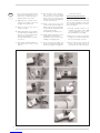
Joint procedure (see figure 6 )
The female end of each Z-Vent III component
incorporates a silicone sealing gasket.
Examine all components to insure that
gasket integrity has remained during ship-
TERMINATION HOOD SVSHTX03
ADAPTER SVSTTA
La page est en cours de chargement...
La page est en cours de chargement...
La page est en cours de chargement...
La page est en cours de chargement...
La page est en cours de chargement...
La page est en cours de chargement...
La page est en cours de chargement...
La page est en cours de chargement...
La page est en cours de chargement...
La page est en cours de chargement...
La page est en cours de chargement...
La page est en cours de chargement...
La page est en cours de chargement...
La page est en cours de chargement...
La page est en cours de chargement...
La page est en cours de chargement...
La page est en cours de chargement...
La page est en cours de chargement...
La page est en cours de chargement...
La page est en cours de chargement...
La page est en cours de chargement...
La page est en cours de chargement...
La page est en cours de chargement...
La page est en cours de chargement...
La page est en cours de chargement...
La page est en cours de chargement...
La page est en cours de chargement...
La page est en cours de chargement...
La page est en cours de chargement...
La page est en cours de chargement...
La page est en cours de chargement...
La page est en cours de chargement...
La page est en cours de chargement...
La page est en cours de chargement...
La page est en cours de chargement...
La page est en cours de chargement...
La page est en cours de chargement...
La page est en cours de chargement...
La page est en cours de chargement...
La page est en cours de chargement...
La page est en cours de chargement...
La page est en cours de chargement...
La page est en cours de chargement...
La page est en cours de chargement...
La page est en cours de chargement...
La page est en cours de chargement...
La page est en cours de chargement...
La page est en cours de chargement...
La page est en cours de chargement...
La page est en cours de chargement...
La page est en cours de chargement...
La page est en cours de chargement...
La page est en cours de chargement...
La page est en cours de chargement...
La page est en cours de chargement...
La page est en cours de chargement...
-
 1
1
-
 2
2
-
 3
3
-
 4
4
-
 5
5
-
 6
6
-
 7
7
-
 8
8
-
 9
9
-
 10
10
-
 11
11
-
 12
12
-
 13
13
-
 14
14
-
 15
15
-
 16
16
-
 17
17
-
 18
18
-
 19
19
-
 20
20
-
 21
21
-
 22
22
-
 23
23
-
 24
24
-
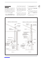 25
25
-
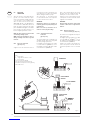 26
26
-
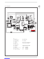 27
27
-
 28
28
-
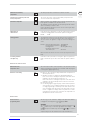 29
29
-
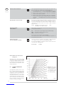 30
30
-
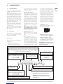 31
31
-
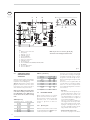 32
32
-
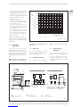 33
33
-
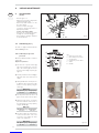 34
34
-
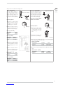 35
35
-
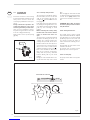 36
36
-
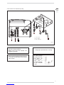 37
37
-
 38
38
-
 39
39
-
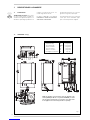 40
40
-
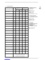 41
41
-
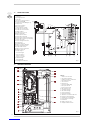 42
42
-
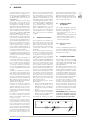 43
43
-
 44
44
-
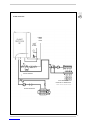 45
45
-
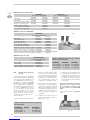 46
46
-
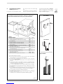 47
47
-
 48
48
-
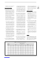 49
49
-
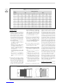 50
50
-
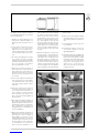 51
51
-
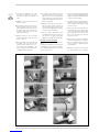 52
52
-
 53
53
-
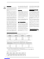 54
54
-
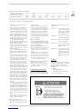 55
55
-
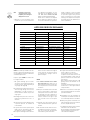 56
56
-
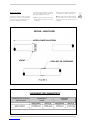 57
57
-
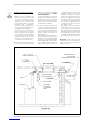 58
58
-
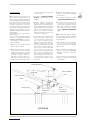 59
59
-
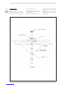 60
60
-
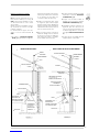 61
61
-
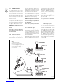 62
62
-
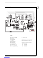 63
63
-
 64
64
-
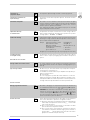 65
65
-
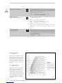 66
66
-
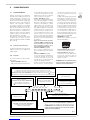 67
67
-
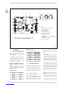 68
68
-
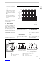 69
69
-
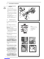 70
70
-
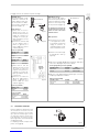 71
71
-
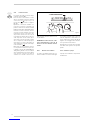 72
72
-
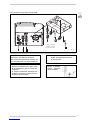 73
73
-
 74
74
-
 75
75
-
 76
76


Sime Planet Dewy 30 Installation Instruction And Care Manual
- Taper
- Installation Instruction And Care Manual
dans d''autres langues
- English: Sime Planet Dewy 30
Documents connexes
Autres documents
-
Baxi Luna 3 Comfort 310 Fi Installation And Servicing Instructions
-
Baxi LUNA HT 1.650 Installation And Servicing Instructions
-
Dunkirk DWB Series Installation, Operation & Maintenance Manual
-
-