La page est en cours de chargement...

40102PA JAN 2012
1
Maintenance & Operating Instructions
For
Dixon DBC & DBS Series Dry Disconnects
Part Numbers
Part # Aluminum Body Part # Stainless Steel Body
DBC61-150 1 ½” Buna Seal, Alum/SST Internals DBC71-150 1 ½” Buna Seal, Stainless Steel
DBC61-200 2” Buna Seal, Alum/SST Internals DBC71-200 2” Buna Seal, Stainless Steel
DBC62-150 1 ½” Viton Seal, Alum/SST Internals DBC72-150 1 ½” Viton Seal, Stainless Steel
DBC62-200 2” Viton Seal, Alum/SST Internals DBC72-200 2” Viton Seal, Stainless Steel
DBC63-150 1 ½” PTFE/Kalrez Seal, Alum/SST Internals DBC72-200-GL 2” Viton Seal, Stainless Steel Greaseless
DBC63-200 2” PTFE/Kalrez Seal, Alum/SST Internals DBC73-150 1 ½” PTFE Encapsulated Viton/Kalrez Seal, Stainless Steel
DBC64-150 1 ½” EPDM Seal, Alum/SST Internals DBC73-200 2” PTFE Encapsulated Viton/Kalrez Seal, Stainless Steel
DBC64-200 2" EPDM Seal, Alum/SST Internals DBC74-150 1 ½” EPDM Seal, Stainless Steel
DBC66-200 2” Kalrez/PTFE Seal, Alum/SST Internals DBC74-200 2” EPDM Seal, Stainless Steel
DBS61-200
2” Buna Seal, Alum/SST Internals, 90° Swivel
DBC76-150 1 ½” Kalrez/PTFE Seal, Stainless Steel
DBS62-200
2” Viton Seal, Alum/SST Internals, 90° Swivel
DBC76-200 2” Kalrez/PTFE Seal, Stainless Steel
DBS63-200 2” PTFE/Kalrez Seal, Alum/SST Internals, 90° Swivel DBC77-150 1 ½” PTFE Encapsulated Viton/Kalrez Seal, Stainless Steel
DBC77-200 2" PTFE Encapsulated Viton/Kalrez Seal, Stainless Steel
DBC77-200-GL
2" PTFE Encapsulated Viton/Kalrez Seal, Stainless Steel -
Greaseless
DBC77-150-GL
1 ½” PTFE Encapsulated Viton/Kalrez Seal, Stainless Steel -
Greaseless
USA:
Dixon Bayco USA
Chestertown, Maryland
Phone: 410-778-2000
Fax: 410-778-4702
Toll Free: 800-355-1991
E-mail: dixonbayco@dixonvalve.com
www.dixonbayco.com
Canada:
Dixon Group Canada Limited
Innisfil (Barrie), Ontario
Phone: 705-436-1125
Fax: 705-436-6251
Toll Free: 877-963-4966
E-mail: isales@dixongroupcanada.com
www.dixongroupcanada.com
Mexico:
Dixva, S. de R.L. de C.V.
Monterrey, N.L
Phone: 01-800-00-DIXON (34966)
Fax: 01-81-8354-8197
E-mail: contactenos@dixonvalve.com.mx
www.dixonvalve.com
Europe:
Dixon Group Europe Ltd
Preston, England
Phone: +44 (0)1772 323529
Fax: +44 (0)1772 314664
E-mail: enquiries@dixoneurope.co.uk
www.dixoneurope.co.uk
Asia Pacific:
Dixon (Asia Pacific) Pty Ltd
Wingfield, South Australia
Phone: +61 8 8202 6000
Fax: +61 8 8202 6099
E-mail: enquiries@dixonvalve.com.au
www.dixonvalve.com.au
For Sales & Service Contact

40102PA 2 JAN 2012

40102PA 3 JAN 2012
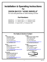
BASIC UNIT

40102PA 4 JAN 2012
OPERATING INSTRUCTIONS:
These products are designed to operate as Dry Disconnect cam and groove couplings. They are to
be used in place of standard cam and groove couplings when it is desired to prevent product from
spilling from the fittings upon disconnect. This product is not intended to be the primary flow control
or flow shut off device. Just as with standard cam and groove fittings, it is intended that a flow
control and flow shutoff valve will be installed in the system.
To use these fittings, attach the coupler to the mating adapter by opening the two cam arms,
sliding the coupler over the mating adapter and closing the two cam arms. This operation is similar
to using standard cam and groove fittings. Make certain that both cam arms are fully closed and
locked.
To open the fittings, rotate the lever on the coupler approximately 190° counterclockwise until it
moves into an over center position and remains in place. At this time, the flow control valve can be
opened to transfer product.
After the product has been transferred, close the flow control valve, then rotate the coupler lever
clockwise until it returns to its over center closed position and remains in place. Unlock the cam
arms and rotate them to the open position using the pull rings for assistance as required. If the
coupler lever will not remain in the closed position on its own, do not disengage the cam arms until
the piping system and hoses have been drained.
Care must be taken in the design of the piping system to avoid trapping liquid between a shut off
valve and a Dry Disconnect Coupler or Adapter. If liquid is trapped in this manner and the
temperature increases, the pressure in the closed volume will rise dramatically and the Dry
Disconnect fitting will be damaged.
DISASSEMBLY INSTRUCTIONS:
1. If your unit is a DBS series coupler (it has a swivel on the end), remove the four screws that
hold the FLANGE RETAINERS in place.
2. Remove the four FLANGE RETAINER plates and pull the SWIVEL TAIL from the BODY.
3. Remove MAIN GASKET from BODY. If MAIN GASKET is a PTFE Encapsulated style, it is
acceptable to leave the MAIN GASKET in place.
4. Insert a BLANK ADAPTER (an adapter end from a DBA style Dry Disconnect Adapter) into
the coupler and close and lock the CAM ARMS.
5. Remove the COTTER PIN from the CAM SHAFT and discard.
6. Remove the PIN from the LEVER by driving out with a hammer and punch.
7. Remove the SCREW from the side of the LEVER.

40102PA 5 JAN 2012
8. Remove the LEVER from the CAM SHAFT. It may be necessary to gently pry the LEVER
from the CAM SHAFT using the blade of a screwdriver. It may also be helpful to insert the
blade of a screwdriver into the slot of the LEVER to spread the LEVER open.
9. Unthread the STUFFING BOX from the BODY. Take care not to scratch the sealing
surfaces inside of the STUFFING BOX
10. You may remove and discard the O-RING on the STUFFING BOX as well as the BEARING
if these are items that are being replaced due to wear. The BEARING is pressed in place so
you will need to use a pin with shoulder to remove the BEARING.
11. Manually manipulate and rotate the CAM SHAFT while disengaging from the LINK. Take
care not to loose the WASHER as it comes off of the end of the CAM SHAFT. It may be
helpful to rotate the LINK using needle nose pliers while disengaging from the CAM SHAFT.
12. Remove the CAM SHAFT from the BODY taking care not to scratch the sealing surface of
the CAM SHAFT.
13. Slide the POPPET with LINK attached out through the BLANK ADAPTER. Take care not to
scratch the sealing and guide surfaces of the POPPET. If you are replacing the O-RING
under the head of the SCREW in the POPPET, then remove the SCREW from the POPPET
and discard the O-RING.
14. The final step is to remove the SEAL CYLINDER. Follow these instructions carefully to avoid
injury and damage to the product. Keep your face and head off to the side of the open end
of the coupler body. DO NOT look directly down into the POPPET area of the coupler. If the
SEAL CYLINDER is released un-expectedly, injury will result.
a. Manually press the BLANK ADAPTER into the BODY. If you removed the GASKET
per the steps above, you will feel the BLANK ADAPTER move away from the CAM
ARMS. Maintain 30 to 35 pounds of force against the BLANK ADAPTER to prevent
the SPRING from suddenly ejecting the SEAL CYLINDER.
b. While still maintaining the 30 to 35 pounds of force against the SEAL CYLINDER,
unlock the two CAM ARMS and rotate and hold in the open position using your
fingers and thumb of the hand not pressing down on the BLANK ADAPTER.
c. With the two CAM ARMS held open, slowly decrease the holding force on the BLANK
ADAPTER allowing it to move out of the BODY.
d. WARNING, the guide BUTTONS on the SEAL CYLINDER may temporarily catch on
the O-RING that seals the SEAL CYLINDER. DO NOT remove all holding force on
the BLANK ADAPTER until the guide BUTTONS are free and clear of the SEAL
CYLINDER O-RING.
e. If the guide BUTTONS prevent the SEAL CYLINDER from releasing from the BODY,
gently move the SEAL CYLINDER in an orbital fashion while pressing the SEAL
CYLINDER down into the BODY and then allowing it to come back into contact with
the O-RING.
f. If you are unable for any reason to remove the SEAL CYLINDER, depress the SEAL
CYLINDER back into the BODY and re-secure the BLANK ADAPTER using the CAM
ARMS. Never allow a partially disassembled unit to remain unattended. The SEAL
CYLINDER could be ejected from the body unexpectedly and cause injury.

40102PA 6 JAN 2012
15. Remove the SEAL CYLINDER and SPRING from the BODY. If you are repairing the SEAL
CYLINDER NOSE SEAL, discard the SEAL CYLINDER if it has a molded on NOSE SEAL.
If the NOSE SEAL is a separate PTFE piece, then just the PTFE NOSE SEAL needs to be
discarded.
16. Remove and discard the BUSHING inside of the SEAL CYLINDER if it is worn, it needs to
be replaced. Remove and discard the guide BUTTONS on the outside of the SEAL
CYLINDER if they need to be replaced.
17. Remove the O-RING in the BODY that seals the SEAL CYLINDER if it is being replaced. A
small brass hook may be used to extract this seal. Take care not to scratch the sealing
surfaces inside of the O-RING groove or the SEAL CYLINDER bore.
REASSEMBLY INSTRUCTIONS:
Prior to reassembly, inspect all components for damage especially scratches to the sealing
surfaces. Pay close attention to the BODY, POPPET, SEAL CYLINDER, STUFFING BOX, and
CAM SHAFT. If you are re-using any seals, inspect them to make sure there are no cracks or
locations showing wear. When in doubt, it is often better to replace a seal at this stage rather than
tear the unit down again.
CAUTION: All lubricants used in the assembly of Dry Disconnects must be compatible with
the seal material used and also with the commodity being transferred through these fittings.
1. Assemble two CAM ARMS to the BODY using two pins. Position the CAM ARMS between
the ears in the BODY and hammer two pins through the holes in the BODY ears and CAM
ARMS.
2. Attach the LINK to the YOKE using the PIN and COTTER PIN. Flare the end of the
COTTER PIN completely.
3. Thread the YOKE, with LINK attached, into the POPPET a few turns and loosely insert the
SET SCREW into the POPPET.
4. Press BEARING into STUFFING BOX using red Loctite #277 on the BEARING prior to
pressing into place. Take care not to get the Loctite on the inside of the BEARING.
5. Install the O-RING over the STUFFING BOX threads and seat against the hex shoulder.
6. Insert the BACKUP RING into the STUFFING BOX.
7. Lubricate the STUFFING BOX O-RING and insert into the STUFFING BOX.
8. Press new guide BUTTONS into the outside diameter of the SEAL CYLINDER and apply a
liberal coating of grease to the SEAL CYLINDER outside diameter.
a. If unit uses a PTFE NOSE SEAL, insert that NOSE SEAL into the end of the SEAL
CYLINDER.
9. Insert the BUSHING inside of the SEAL CYLINDER.

40102PA 7 JAN 2012
10. Insert the SEAL CYLINDER O-RING into the groove in the BODY. Apply a liberal coating of
grease to the O-RING and to the bore of the BODY where the SEAL CYLINDER will be
placed.
a. If the unit uses a PTFE O-RING, take care not to crease the O-RING when inserting it
into the BODY groove. The O-RING should be lubricated and inserted into the BODY
bore such that the O-RING goes past the groove. Then the O-Ring is pulled back up
into the groove and worked around until it is in the groove.
11. Place the SPRING and assembled SEAL CYLINDER into the BODY.
12. Center the BLANK ADAPTER on the SEAL CYLINDER and while holding the CAM ARMS
open, press the SEAL CYLINDER into the BODY using an orbital motion to ease the SEAL
CYLINDER BUTTONS past the O-RING in the BODY.
13. While holding the SEAL CYLINDER securely against the SPRING force, close and lock the
CAM ARMS. You can now release the force on the BLANK ADAPTER
14. Insert the POPPET, with YOKE and LINK attached, through the opening in the BLANK
ADAPTER and into the SEAL CYLINDER.
15. Insert the CAM SHAFT through the STUFFING BOX opening in the BODY and insert the
end of the CAM SHAFT through the hole in the LINK. You may need to rotate and move the
POPPET up and down in the BODY and rotate the CAM SHAFT in order to get the end of
the CAM SHAFT through the hole in the LINK.
16. Insert the WASHER onto the end of the CAM SHAFT after it has passed through the LINK
and then insert the CAM SHAFT into the bearing in the BODY.
17. If the BODY is stainless steel, apply “Never Seize” to the STUFFING BOX threads. Install
the assembled STUFFING BOX over the end of the CAM SHAFT and tighten into the
BODY. Take care not to damage the O-RING in the STUFFING BOX as it slides onto the
CAM SHAFT.
18. Install the LEVER onto the hex end of the CAM SHAFT. The small projection on the CAM
SHAFT hex, points toward the portion of the LEVER that your hand will grip.
19. Insert the GROOVE PIN into the hole in the LEVER until it has gone past the gap in the
LEVER and into the hole on the opposite side of the LEVER. Do not hammer the pin into
place at this time.
20. Slide the LOCK WASHER over the LEVER SCREW and apply “Never Seize” to the LEVER
SCREW.
21. Install the SCREW into the LEVER and tighten firmly to squeeze the LEVER against the hex
of the CAM SHAFT.
22. Hammer the GROOVE PIN into the LEVER until flush.
23. Turn the coupler so that you can look into the open end nearest the LEVER.

40102PA 8 JAN 2012
24. Slide the Washer that was installed onto the CAM SHAFT such that it is up against the Link.
25. Insert the COTTER PIN into the hole in the CAM SHAFT and using the LEVER to rotate the
CAM SHAFT as needed, completely flair the COTTER PIN.
26. Adjust the POPPET by rotating the LEVER to the open position and rotating the POPPET
left or right to increase or decrease the compression on the SEAL CYLINDER. The
POPPET is properly adjusted when the seal on the SEAL CYLINDER is just barely
separated from the face of the BLANK ADAPTER (about 1/32”) when the coupler LEVER is
rotated to the closed position. There will be a noticeable ‘over center’ feel to the lever as it
enters its closed position. The LEVER should stay closed when rotated to its closed
position. If it does not, open the LEVER and readjust the POPPET by threading it down
further into the BODY then repeat this step.
27. With the POPPET correctly adjusted, tighten the SET SCREW in the POPPET securely
against the YOKE. This is necessary to prevent the POPPET from rotating out of
adjustment.
28. Install the O-RING under the head of the POPPET SCREW. Apply “Never Seize” to the
SCREW and tighten into the POPPET
29. With the coupler in the closed position, unlock and open the CAM ARMS and remove the
BLANK ADAPTER
30. Install the main GASKET.
31. While holding the coupler BODY firmly, push the LEVER towards the open position and
allow the coupler to open itself using the spring force against the SEAL CYLINDER. The
coupler should ‘snap’ to the open without delay and the SEAL CYLINDER movement should
remain in contact with the POPPET movement. If the SEAL CYLINDER separates from the
POPPET or if the movement is ‘sluggish’, do not return this unit to service.
32. If your unit is a DBS series coupler (it has a swivel on the end), assemble the two
BEARINGS to the SWIVEL TAIL with the O-RING between the two BEARINGS.
33. Assemble the split WASHER to the SWIVEL TAIL so that it is on the opposite side of the
metal flange from the previously installed BEARINGS.
34. Liberally apply grease to the BEARINGS and O-RING and also to the bore in the BODY and
then push the SWIVEL TAIL into the BODY.
35. Install two FLANGE RETAINERS onto the square BODY flange. Install two more FLANGE
RETAINERS on top of the previously installed FLANGE RETAINERS and position them 90°
from the first two FLANGE RETAINERS such that the gaps between the FLANGE
RETAINERS to not line up.
36. Apply “Never Seize” to four SCREWS with LOCK WASHERS and install through the holes
in the FLANGE RETAINERS and into the body and tighten.

40102PA 9 JAN 2012
TEST PROCEDURE:
The procedure for testing these products involves applying pressure to the coupler, submerging the
coupler under water and checking for the appearance of bubbles. Generally the appearance of
bubbles indicates a leak and is cause for rejection. There is often trapped air in various parts of the
unit so the tester needs to make sure that the bubbles being seen are a leak (a steady repeating
bubbling pattern) and not merely trapped air being released.
CAUTION: Safety glasses must always be worn when using compressed air
for any testing.
CAUTION: Never rotate the LEVER to the open position while the coupler is
under pressure and not coupled to a Dry Disconnect Adapter. This action can
cause the LEVER to rapidly rotate and cause injury.
1. Install a test plug with air line adapter into the threaded end of the coupler.
2. With LEVER in closed position, pressurize the coupler to between 3 P.S.I.G. and 5 P.S.I.G.
Submerge under water and check for leaks. (Low Pressure Closed)
3. Remove pressure and rotate LEVER to the open position.
4. Pressurize the coupler to between 3 P.S.I.G. and 5 P.S.I.G. Submerge under water and
check for leaks. (Low Pressure Open)
5. Increase pressure to 30 P.S.I.G. while still under water and check for leaks. (High Pressure
Open)
6. Remove pressure, remove unit from water and close LEVER.
7. Pressurize the unit to 30 P.S.I.G. Submerge under water and check for leaks. (High
Pressure Closed)
8. Remove all pressure from the coupler and remove from the water.
9. Install a Dry Disconnect Adapter equipped with a plug in its threaded end. Make sure both
CAM ARMS are closed and locked.
10. Rotate the LEVER to its open position and apply between 3 P.S.I.G. and 5 P.S.I.G. to the
coupler.
11. Submerge under water and check for leaks at the MAIN GASKET. (Coupler to Adapter
interface) DO NOT CLOSE LEVER!
12. Increase pressure to 30 P.S.I.G. while still under water and check for leaks at the MAIN
GASKET. (Coupler to Adapter interface) DO NOT CLOSE LEVER!

40102PA 10 JAN 2012
13. Remove all pressure from the coupler. Remove from the water. Disconnect the air line from
the test plug in the coupler.
14. Rotate the Lever to the closed position.
15. Unlock and open the CAM ARMS and remove the Dry Disconnect Adapter.
REPAIR KITS:
REPAIR PARTS KITS FOR CAM AND GROOVE DRY DISCONNECT COUPLERS (DBC & DBS SERIES)
BASE KIT #
SIZE
REPAIR KIT
QTY
ITEM #
DESCRIPTION
ADDITIONAL DESCRIPTION
ALL SEALS
DBCX1
150
RK1
1
4
O-RING
STUFFING BOX TO CAM SHAFT
BUNA-N
1
5
O-RING
STUFFING BOX TO BODY
1
13
O-RING
SEAL CYL TO BODY
1
18
GASKET
MAIN CAM & GROOVE GASKET
1
23
O-RING
POPPET SCREW SEAL
DBCX1
200
RK1
1
4
O-RING
STUFFING BOX TO CAM SHAFT
BUNA-N
1
5
O-RING
STUFFING BOX TO BODY
1
13
O-RING
SEAL CYL TO BODY
1
18
GASKET
MAIN CAM & GROOVE GASKET
1
23
O-RING
POPPET SCREW SEAL
DBCX2
150
RK1
1
4
O-RING
STUFFING BOX TO CAM SHAFT
VITON
1
5
O-RING
STUFFING BOX TO BODY
1
13
O-RING
SEAL CYL TO BODY
1
18
GASKET
MAIN CAM & GROOVE GASKET
1
23
O-RING
POPPET SCREW SEAL
DBCX2
200
RK1
1
4
O-RING
STUFFING BOX TO CAM SHAFT
VITON
1
5
O-RING
STUFFING BOX TO BODY
1
13
O-RING
SEAL CYL TO BODY
1
18
GASKET
MAIN CAM & GROOVE GASKET
1
23
O-RING
POPPET SCREW SEAL
DBCX3
150
RK1
1
4
O-RING
STUFFING BOX TO CAM SHAFT
PTFE &
1
5
O-RING
STUFFING BOX TO BODY
CHEMRAZ
1
13
O-RING
SEAL CYL TO BODY
1
18
GASKET
MAIN CAM & GROOVE GASKET
1
23
O-RING
POPPET SCREW SEAL
DBCX3
200
RK1
1
4
O-RING
STUFFING BOX TO CAM SHAFT
PTFE &
1
5
O-RING
STUFFING BOX TO BODY
CHEMRAZ
1
13
O-RING
SEAL CYL TO BODY
1
18
GASKET
MAIN CAM & GROOVE GASKET
1
23
O-RING
POPPET SCREW SEAL

40102PA 11 JAN 2012
SEAL CYLINDER
DBC61
150
RK2
1
9
SEAL CYL
ALUM & BUNA
1
12
BUSHING
6
10
BUTTONS
DBC61
200
RK2
1
9
SEAL CYL
ALUM & BUNA
1
12
BUSHING
6
10
BUTTONS
DBC62
150
RK2
1
9
SEAL CYL
ALUM & VITON
1
12
BUSHING
6
10
BUTTONS
DBC62
200
RK2
1
9
SEAL CYL
ALUM & VITON
1
12
BUSHING
6
10
BUTTONS
DBC71
150
RK2
1
9
SEAL CYL
SST & BUNA
1
12
BUSHING
6
10
BUTTONS
DBC71
200
RK2
1
9
SEAL CYL
SST & BUNA
1
12
BUSHING
6
10
BUTTONS
DBC72
150
RK2
1
9
SEAL CYL
SST & VITON
1
12
BUSHING
6
10
BUTTONS
DBC72
200
RK2
1
9
SEAL CYL
SST & VITON
1
12
BUSHING
6
10
BUTTONS
DBCX3
150
RK2
1
37
NOSE SEAL
PTFE
1
12
BUSHING
6
10
BUTTONS
DBCX3
200
RK2
1
37
NOSE SEAL
PTFE
1
12
BUSHING
6
10
BUTTONS
MAIN GASKET
DBCX1
150
RK3
1
18
GASKET
MAIN CAM & GROOVE GASKET
BUNA-N
DBCX1
200
RK3
1
18
GASKET
MAIN CAM & GROOVE GASKET
BUNA-N
DBCX2
150
RK3
1
18
GASKET
MAIN CAM & GROOVE GASKET
VITON

40102PA 12 JAN 2012
DBCX2
200
RK3
1
18
GASKET
MAIN CAM & GROOVE GASKET
VITON
DBCX3
150
RK3
1
18
GASKET
MAIN CAM & GROOVE GASKET
PTFE-SI
DBCX3
200
RK3
1
18
GASKET
MAIN CAM & GROOVE GASKET
PTFE-SI
LINK & YOKE SUB ASSY
DBCXX
150
RK4
1
14
LINK RIVET
2
16
COTTER PIN
1
22
WASHER
1
21
LINK
1
11
YOKE
DBCXX
200
RK4
1
14
LINK RIVET
2
16
COTTER PIN
1
22
WASHER
1
21
LINK
1
11
YOKE
STUFFING BOX
DBCXX
150
RK5
1
2
STUFFING BOX
1
6
BEARING
PRESSED IN STUFFING BOX
1
5
O-RING
STUFFING BOX TO BODY
DBCXX
200
RK5
1
2
STUFFING BOX
1
6
BEARING
PRESSED IN STUFFING BOX
1
5
O-RING
STUFFING BOX TO BODY
LEVER (HANDLE)
DBCXX
150
RK6
1
8
LEVER
1
15
GROOVE PIN
1
27
LOCKWASHER
1
28
SCREW
DBCXX
200
RK6
1
8
LEVER
1
15
GROOVE PIN
1
27
LOCKWASHER
1
28
SCREW
CAM SHAFT
DBCXX
150
RK7
1
20
CAM SHAFT
1
16
COTTER PIN
1
22
WASHER

40102PA 13 JAN 2012
DBCXX
200
RK7
1
20
CAM SHAFT
1
16
COTTER PIN
1
22
WASHER
MAIN SPRING
DBCXX
150
RK8
1
24
SPRING
DBCXX
200
RK8
1
24
SPRING
POPPET
DBCXX
150
RK9
1
19
POPPET
1
26
SCREW
ROUND HEAD
1
25
SET SCREW
1
23
O-RING
DBCXX
200
RK9
1
19
POPPET
1
26
SCREW
ROUND HEAD
1
25
SET SCREW
1
23
O-RING

40102PA 14 JAN 2012
DIXON WARRANTY:
For Warranty Information, please refer to the inside back cover of the latest Dixon
Catalogue.
Waste Disposal
"Kalrez" perfluoroelastomer semi-finished parts and shapes
generally may be disposed of by landfill or incineration,
but any disposal method selected must be in accordance with
applicable federal, state/provincial and local regulations.
If incineration is employed, the incinerator must be capable
of scrubbing out acidic combustion products. Note:
Semi-finished parts and shapes made from compounds 1058 and
3065 contain lead oxide and particular requirements may
apply (see, e.g., 40 C.F.R. 261.24). A waste generator
should perform a waste characterization before disposing and
manage and dispose in accordance with all potentially
applicable laws and regulations including the Resource
Conservation and Recovery Act.

40102PA(fr) 1 JAN 2012
Entretien & Mode d’emploi
pour
Raccords rapides pour transfère sécurisés Dixon série DBC & DBS de 1 ½” et 2”
# De la
pièce
Pièce en Aluminium
# De la
pièce
Pièce en Acier Inoxydable
DBC61-150
Joint de Buna de 1½”, Intérieur Alum/SS
DBC71-150 Joint de Buna de 1½” en Acier Inoxydable
DBC61-200
Joint de Buna de 2”, Intérieur Alum/SS DBC71-200
Joint de Buna de 2” en Acier Inoxydable
DBC62-150 Joint de Viton de 1½”, Intérieur Alum/SS
DBC72-150 Joint de Viton de 1½” en Acier Inoxydable
DBC62-200
Joint de Viton de 2”, Intérieur Alum/SS
DBC72-200 Joint de Viton de 2” en Acier Inoxydable
DBC63-150 Joint de Silicone/Kalrez de 1½”, Intérieur Alum/SS
DBC72-200-GL
Joint de Viton de 2” en Acier Inoxydable sans graisse
DBC63-200 Joint de Silicone/Kalrez de 2”, Intérieur Alum/SS
DBC73-150 Joint de Silicone/Kalrez avec PTFE encapsulé de 1½ ” en Acier Inoxydable
DBC64-150
Joint de EPMD de 1½”, Intérieur Alum/SS
DBC73-200
Joint de Silicone/Kalrez avec PTFE encapsulé de 1½ ” en Acier Inoxydable
DBC64-200 Joint de EPMD de 2”, Intérieur Alum/SS
DBC74-150 Joint de EPMD de 1½” en Acier Inoxydable
DBC66-150
Joint de PTFE/Kalrez de 1½”, Intérieur Alum/SS
DBC74-200 Joint de EPMD de 2” en Acier Inoxydable
DBC66-200
Joint de PTFE/Kalrez de 2”, Intérieur Alum/SS
DBC76-150 Joint de Kalrez/PTFE de 1½” en Acier Inoxydable
DBC67-150
Joint de Viton/Kalrez de 1½”, Intérieur Alum/SS
DBC76-200 Joint de Kalrez/PTFE de 2” en Acier Inoxydable
DBC67-200 Joint de Viton/Kalrez de 2”, Intérieur Alum/SS
DBC77-150 Joint de Viton/Kalrez avec PTFE encapsulé de 1½ ” en Acier Inoxydable
DBS61-200
Joint de Buna de 2”, Intérieur Alum/SS, pivot de 90º
DBC77-200
Joint de Viton/Kalrez avec PTFE encapsulé de 2 ” en Acier Inoxydable
DBS62-200
Joint de Viton de 2”, Intérieur Alum/SS, pivot de 90º
DBC77-150-GL Joint de Viton/Kalrez avec PTFE encapsulé de 1½ ” en Acier Inoxydable sans graisse
DBS63-200 Joint de PTFE/Kalrez de 2”, Intérieur Alum/SS, pivot de 90º
DBC77-200-GL
Joint de Viton/Kalrez avec PTFE encapsulé de 2 ” en Acier Inoxydable sans graisse
E-U:
Dixon Bayco USA
Chestertown, Maryland
Téléphone: 410-778-2000
Fax: 410-778-4702
Sans frais: 800-355-1991
E-mail: dixonbayco@dixonvalve.com
www.dixonbayco.com
Canada:
Dixon Group Canada Limited
Innisfil (Barrie), Ontario
Téléphone: 705-436-1125
Fax: 705-436-6251
Sans frais: 877-963-4966
E-mail: isales@dixongroupcanada.com
www.dixongroupcanada.com
Mexique:
Dixva, S. de R.L. de C.V.
Monterrey, N.L
Téléphone: 01-800-00-DIXON (34966)
Fax: 01-81-8354-8197
E-mail :contactenos@dixonvalve.com.mx
www.dixonvalve.com
Europe:
Dixon Group Europe Ltd
Preston, England
Téléphone: +44 (0)1772 323529
Fax: +44 (0)1772 314664
E-mail: enquiries@dixoneurope.co.uk
www.dixoneurope.co.uk
Asie et Pacifique:
Dixon (Asia Pacific) Pty Ltd
Wingfield, South Australia
Téléphone: +61 8 8202 6000
Fax: +61 8 8202 6099
E-mail:enquiries@dixonvalve.com.au
www.dixonvalve.com.au
Pour vente & service contactez

40102PA(fr) 2 JAN 2012

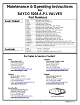
MODÈLE DE BASE
40102PA(fr) 3 JAN 2012

INSTRUCTION DE FONCTIONNEMENT:
Ces produits sont conçus pour fonctionner comme des raccords rapides came et groove pour des
transfères sécurisé et les raccords. Ils doivent être utilisés à la place des raccords came & groove
lorsqu’on veut empêcher des renversements pendant les déconnexions. Ce produit n’est pas
conçu pour être le contrôle de débit primaire ou un appareil d’arrêt de débit. Tout comme les
raccords came et groove standards, il est prévu qu’un contrôle de débit et une valve d’arrêt seront
installés dans le système.
Pour utiliser ses raccords, attachez le raccord de l’adaptateur d’accouplement avec l’adaptateur en
ouvrant les deux bras de came, glissez le coupleur sur l’adaptateur et en fermant des deux bras de
came. Cette opération est similaire à l’utilisation d’un raccord came and groove. Assurez-vous que
les deux bras soient fermés et verrouillés.
Pour ouvrir les raccords, tournez le levier sur le coupleur à approximativement 190° au sens
contraire des aiguilles d’une montre jusqu’à ce qu’il soit déplacé dans une position par-dessus le
centre et qu’il reste en place. À ce point, la valve de contrôle de débit peut être ouverte pour
transfère de produit.
Après que le produit ait été transféré, fermez la valve de contrôle de débit, ensuite tournez le levier
du coupleur au sens des aiguilles d’une montre jusqu’à ce qu’il retourne dans une position par-
dessus le centre et reste en place. Débarrez les bras de came et tournez-les dans la position
ouverte en utilisant les anneaux comme assistance si nécessaire. Si le levier du coupleur ne reste
pas en position fermée seul ne relâchez pas les bras de came jusqu’à ce que le système de
tuyauterie et le boyau soient vidés.
Des précautions doivent être prises dans la conception de la tuyauterie pour éviter de piéger les
liquides entre la valve de fermeture et le coupleur ou l’adaptateur pour transfère sécurisés ou
l’adaptateur. Si le liquide est piégé et la température augmente, la pression augmentera
énormément et le raccord rapide pour transfère sécurisé pourrait être endommagé.
INSTRUCTIONS DE DÉSASSEMBLAGE:
1. Si votre unité est un coupleur de la série DBS (il a un pivot au bout), retirez les quatre vis
qui retiennent les bride de retenu en place.
2. Retirez les quatre plaques de la bride de retenu et retirez l’arrière du pivot hors du corps de
l’unité.
3. Retirez le joint d’étanchéité principal de la pièce. Si le joint principal est d’un style en PTFE
encapsulé, il est acceptable de laisser le joint principal en place.
4. Insérez un adaptateur dans le coupleur et fermez et verrouiller les bras de came.
5. Retirez la goupille de l’arbre de came et jetez-la.
6. Retirez la goupille du levier en utilisant un marteau et un poinçon.
7. Retirez la vis sur le coté du levier.
40102PA(fr) 4 JAN 2012

8. Retirez le levier de l’arbre de came. Il pourrait être nécessaire de soulever doucement le
levier de l’arbre de came en utilisant la lame d’un tournevis. Il pourrait être utile d’insérer la
lame d’un tournevis dans la fente du levier pour répandre ouvrir le levier dans une position
ouverte.
9. Dévissez le presse-étoupe de la pièce. Faites attention pour ne pas graver les surfaces
d’étanchéité à l’intérieur du presse-étoupe.
10. Vous pouvez retirez et jetez le joint torique du presse étoupe ainsi que le roulement, si ce
sont des éléments qui sont remplacés en raison de l’usure. Le roulement est enfoncé en
place de façon que vous devrez utilisez une épingle pour enlever le roulement.
11. Manipulez manuellement et tournez l’arbre de came en relâchant le lien. Faites attention
pour ne pas perdre la rondelle car elle se détache du bout de l’arbre pour came. Il peut être
utile de faire tourner le lien à l’aide d’une pince à bec tout en relâchant l’arbre de came.
12. Retirez l’arbre de came de la pièce en prenant soin de ne pas égratigner la surface
d’étanchéité de l’arbre de came.
13. Faites glissez le clapet avec lien attachés à travers l’adaptateur vide. Faites attention à ne
pas égratigné la surface d’étanchéité la surface de guidage du clapet. Si vous aller
remplacé le joint torique sous la tête de la vis dans le clapet, retirez la vis du clapet et jetez
le joint torique.
14. La dernière étape est de retirez le joint cylindrique. Suivez ces instructions pour éviter des
blessures ou endommager le produit. Gardez votre visage et votre tête sur le coté de
l’extrémité ouverte de la pièce. Ne regardez pas directement vers le bas dans la zone clapet
du coupleur. Si le joint torique est libéré de façon inattendue, un accident pourrait en
résulter.
a. Insérez manuellement sur l’adaptateur dans la pièce. Si vous retirez le joint comme
sur l’étape ci-dessus, vous sentirez l’adaptateur s’éloigner des bras de came. Gardez
30 à 35 livres de force contre l’adaptateur pour empêcher au ressort d’éjecter le joint
cylindrique.
b. En gardant 30 à 35 livres de force contre le joint cylindrique, débarrez les deux bras
de came and tournez-les et gardez-les en position ouverte en utilisant l’autre main
pour appuyer sur l’adaptateur.
c. Avec les deux bras de came ouvert, diminuez doucement la force de maintien de
l’adaptateur pour lui permettre de sortir de la pièce.
d. AVERTISSEMENT, les boutons de guidage sur le joint cylindrique peuvent
temporairement accrocher le joint torique qui scelle le joint cylindrique. Ne retirez pas
toutes la force de maintien sur l’adaptateur jusqu’à ce que les boutons de guidages
soient libres du joint torique du joint cylindrique.
e. Si les boutons de guidages empêchent les joints cylindriques de sortir de la pièce,
déplacez doucement le joint cylindrique de manière orbitale en appuyant sur le joint
cylindrique dans la pièce et en lui permettant de revenir en contact avec le joint
torique.
f. Si pour n’importe quelle raison vous ne pouvez pas enlever le joint cylindrique,
appuyez sur le joint torique dans la pièce et refixer l’adaptateur en utilisant les bras
de came. Ne laisser jamais une pièce partiellement démonté sans surveillance. Le
joint torique pourrait s’éjecter de façon inattendue et causer un accident.
40102PA(fr) 5 JAN 2012

15. Retirez le joint cylindrique et le ressort de la pièce. Si vous réparez un joint du nez du joint
cylindrique jetez le joint cylindrique s’il a un joint moulé sur le nez. Si le joint du nez est une
pièce en PTFE indépendant, dans ce cas seulement le joint du nez devrait être jeté.
16. Enlevez et jetez la bague à l’intérieur du joint cylindrique si elle est usée, remplacez-la.
Enlevez et jetez les boutons de guidages à l’extérieur du joint cylindre s’ils doivent être
remplacé.
17. Retirez le joint torique de la pièce qui scelle le joint cylindrique (si on le remplace). Un petit
crochet de laiton peut être utilisé pour extraire le joint. Faites attention à ne pas égratigner la
surface d’étanchéité à l’intérieur du joint torique ou l’alésage du joint cylindrique.
INSTRUCTIONS DE RÉASSEMBLAGE:
Avant le réassemblage, inspectez tous les composants pour des dommages spécialement les
égratignures sur les surfaces d’étanchéité. Si vous utilisez les mêmes joints, inspectez-les pour
des fissures ou des signes d’usures. En cas de doute, il est souvent préférable de remplacer un
joint à ce stade plutôt que de démonter la pièce de nouveau.
ATTENTION: Tous les lubrifiants utilisés dans l’assemblé des raccords rapides pour
transfère sécurisés doivent être compatible avec le matériel des joints utilisés et aussi avec
les produits qui sont transféré.
1. Assemblez 2 bras de came sur la pièce en utilisant 2 goupilles. Positionnez les bras de
came entre les oreilles sur la pièce et frappez avec un marteau les goupilles dans les trous
des oreilles et des bras de came de la pièce.
2. Attachez les liens au joug en utilisant la goupille et le goupille cylindrique. Évaser le bout de
la goupille cylindrique complètement.
3. Vissez le joug avec le lien attaché au clapet et insérez sans serrer la vis de calage clapet.
4. Appuyez le roulement sur le presse-étoupe en utilisant du Loctite rouge #277. Assurez-vous
de ne pas appliqué du Loctite à l’intérieur du roulement.
5. Installez le joint torique sur les filets du presse-étoupe et placez-le sur l’épaule hexagone.
6. Insérez l’anneau de secours (supplémentaire) dans le presse-étoupe.
7. Lubrifiez le joint torique du presse-étoupe et insérez-le dans le presse-étoupe.
8. Placez les nouveaux boutons de guidages sur le diamètre extérieur du joint cylindrique et
appliquez une bonne couche de graisse sur le diamètre extérieur du joint cylindrique.
a. Si la pièce contient un joint du nez en PTFE, insérez ce joint du nez au bout du joint
cylindrique.
9. Insérez la bague à l’intérieur du joint cylindrique.
40102PA(fr) 6 JAN 2012
/