
090090 R7
1
Maintenance & Operating Instructions
For
BAYCO AIR OPERATED SEQUENTIAL
VAPOR VALVES
Part Numbers:
USA:
Dixon Bayco USA
Chestertown, Maryland
Phone: 410-778-2000
Fax: 410-778-4702
Toll Free: 800-355-1991
E-mail: dixonbayco@dixonvalve.com
www.dixonbayco.com
Canada:
Dixon Group Canada Limited
Innisfil (Barrie), Ontario
Phone: 705-436-1125
Fax: 705-436-6251
Toll Free: 877-963-4966
E-mail: isales@dixongroupcanada.com
www.dixongroupcanada.com
Mexico:
Dixva, S. de R.L. de C.V.
Monterrey, N.L
Phone: 01-800-00-DIXON (34966)
Fax: 01-81-8354-8197
E-mail: contactenos@dixonvalve.com.mx
www.dixonvalve.com
Europe:
Dixon Group Europe Ltd
Preston, England
Phone: +44 (0)1772 323529
Fax: +44 (0)1772 314664
E-mail: enquiries@dixoneurope.co.uk
www.dixoneurope.co.uk
Asia Pacific:
Dixon (Asia Pacific) Pty Ltd
Wingfield, South Australia
Phone: +61 8 8202 6000
Fax: +61 8 8202 6099
E-mail: enquiries@dixonvalve.com.au
www.dixonvalve.com.au
For Sales & Service Contact
VR6030SQ
-
Sequential - Baylast seal - fits standard 16” manhole cover
VR6035SQ - Sequential - Baylast seal - fits standard 20” manhole cover with
3” TTMA flange
VR6030SQV - Sequential - Viton seal - fits standard 16” manhole cover
VR6035SQV - Sequential - Viton seal - fits standard 20” manhole cover with
3” TTMA flange

090090 R7
2
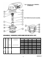
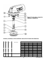
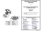
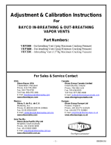
VR6030SQ / VR6030SQ: BOM AND REPAIR KITS LIST
ITEM
NO.
QTY. PART NO. DESCRIPTION
REPAIR KITS
VR6030RK1 VR6030RKV1 VR6030RK2 VR6030RK3 VR6030RKV3
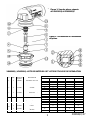
1 1 400636 Stem Assembly
2 1 390823 Piston
Y Y Y
3 1 111681 Retaining Ring
Y Y
4 1 390822 Bearing
5 1 111680 Cotter Pin
Y Y
6 1 111679 Spring
7 1 111683 Bearing Seal Washer
8 2 111686 Lip Seal
Y (X2) Y (X2) Y (X2)
9 1 111687 Lip Seal
Y Y Y
10
1 111008 Mounting Ring
11 1 111692 O-ring #242
Y Y
12 1 341642 Body, 16"
13 1 341643 Poppet
14
1 111691 Poppet Gasket “ Viton”
Y Y
1 112050 Poppet Gasket “Baylast”
Y Y
15 1 111694 Pipe Plug 1/4"
1
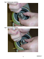
Fig 2- Detailed view of piston assembly
Fig 1
-
Exploded view of VR6030SQ
& VR6030SQV

090090 R7
3
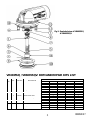
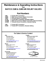
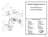
VR6035SQ / VR6035SQV: BOM AND REPAIR KITS LIST
ITEM
NO.
QTY. PART NO. DESCRIPTION
REPAIR KITS
VR6035RK1 VR6035RKV1 VR6035RK2 VR6035RK3 VR6035RKV3
1 1 400636 Stem Assembly
2 1 390823 Piston Y Y Y
3 1 111681 Retaining Ring Y Y
4 1 111680 Cotter Pin
Y Y
5 1 111679 Spring
6 1 111683 Bearing Seal Washer
7 2 111686 Lip Seal Y (X2) Y (X2) Y (X2)
8 1 111687 Lip Seal Y Y Y
9
1 111678 Poppet Gasket “Viton”
Y
Y
1 112049 Poppet Gasket “Baylast” Y Y
10 1 341641 Poppet
11 8 111690 Hex Bolt 3/8-16 UNC-2A x 5/8 lg
12 1 111689 Gasket Y Y
13 8 110935 Lock Washer, 3/8”
14 1 390822 Bearing
15 1 341640 Body, 20"
Fig 3
-
Exploded view of VR6035SQ
& VR6035SQV

090090 R7
4
APPLICATIONS
Bayco air operated vapor valves VR6030SQ / VR6035SQ and VR6030SQV / VR6035SQV may be
used in sequential or non-sequential applications. In sequential applications the valves will not
allow actuating air to proceed to the subsequent compartment valve, or other mechanism, before
the preceding valve has opened (hence venting the compartment).
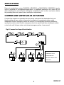
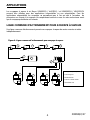
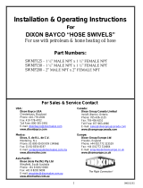
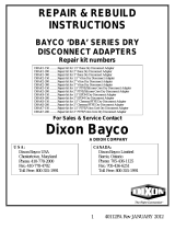
COMMON LINE VAPOR VALVE ACTUATION
Common-line actuation incorporates the vapor valves upstream of the distribution block and
therefore allows all vapor valves to be opened, and hence all compartments to be vented,
independent of which emergency valves are opened. This arrangement should be operated by
opening the selector valve for each emergency valve to be opened and then actuating the master
control valve until all vapor valves, and relevant emergency valves, have opened.
1. SEQUENTIAL VAPOR VALVE
2. EMERGENCY VALVE
3. AIR DISTRIBUTOR
4. MASTER CONTROL VALVE
5. AIR SUPPLY
1
5
2
2
2
2
4
3
1
1
Fig 4- Common Line Vapor Valve Actuation
1

090090 R7
5
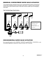
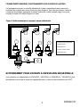
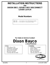
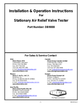
INDIVIDUAL COMPARTMENT VAPOR VALVE ACTUATION
This arrangement allows individual control of each compartment but still retains the interlocked
venting of the compartment before the emergency valve opens. To operate, open the required
selector valve(s) and actuate the master control valve until the selected vapor and emergency
valves open.
NON-SEQUENTIAL VAPOR VALVE ACTUATION
Non-sequential operation of the VR6030SQ / VR6035SQ and VR6030SQV / VR6035SQV can be
achieved by plugging the sequential air outlet port using a ¼”NPT pipe plug.
1. SEQUENTIAL VAPOR VALVE
2. EMERGENCY VALVE
3. AIR DISTRIBUTOR
4. MASTER CONTROL VALVE
5. AIR SUPPLY
1
1
1 1
5
2
2
2 2
4
3
Fig 5- Individual Vapor Valve Actuation

090090 R7
6
MAINTENANCE AND PART REPLACEMENT FOR BAYCO
VR6030SQ / VR6035SQ and VR6030SQV / VR6035SQV AIR
OPERATED SEQUENTIAL VAPOR VALVES
These instructions and recommendations are provided to ensure proper operation and long service
life of Bayco VR6030SQ / VR6035SQ and VR6030SQV / VR6035SQV Air Operated Vapor Valves.
Parts are identified by the item number on the assembly drawing and part list.
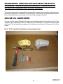
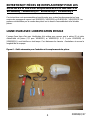
AIR LINE OIL LUBRICATION
The use of an air line oil lubricator will help to ensure that the piston (2) and piston seals (7,8 for
VR6035SQ and VR6035SQV & 8,9 for VR6030SQ and VR6030SQV), are kept correctly lubricated
at all times. This will reduce the requirement for maintenance and ensure the long service life of the
valves.
Fig 6 – Tools required for maintenance and part replacement

090090 R7
7
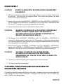
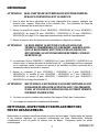
DISASSEMBLY
CAUTION! SAFETY GLASSES MUST BE WORN DURING DISASSEMBLY
AND SERVICE.
1. With unit secured and sequential air outlet plugged, apply air pressure (approx. 20psi) to the
air inlet port. This will cause the poppet to move to the valve open position and allow
access to the internal components.
2. Remove latch pin clip (4 for VR6030SQ / VR6030SQV and 5 for VR6035SQ / VR6035SQV)
from the poppet (10 for VR6035SQ / VR6035SQV & 13 for VR6030SQ / VR6030SQV) and
the stem (1). The poppet can now be removed from the assembly.
3. Remove air pressure from inlet port and allow the stem to retract.
CAUTION! BEARING (5) IS HELD IN PLACE AGAINST CONSIDERABLE
SPRING TENSION. ENSURE THAT THE BEARING IS
SECURELY HELD IN PLACE BEFORE ATTEMPTING TO
REMOVE THE RETAINING RING (4).
4. The Bearing (4 for VR6030SQ / VR6030SQV and 5 for VR6035SQ / VR6035SQV) is
secured by a double-wound retaining ring (4). Disassembly is achieved by pressing down
on the bearing against the spring tension and by working the uppermost free end of the ring
out of the groove on the valve body.
5. Remove bearing (4 for VR6030SQ / VR6030SQV and 5 for VR6035SQ / VR6035SQV),
washer (6 for VR6030SQ / VR6030SQV and 7 for VR6035SQ / VR6035SQV), spring (5 for
VR6035SQ / VR6035SQV and 6 for VR6030SQ / VR6030SQV) and stem assembly (1).
CAUTION! SECURELY COVER THE VALVE BORE BEFORE
ATTEMPTING TO DISLODGE THE PISTON WITH
PRESSURIZED AIR. FAILURE TO DO THIS CAN RESULT IN
SERIOUS INJURY.
6. The Piston is removed by blowing air (at approx 20psi) into the inlet port.
7. The Valve is now fully disassembled.
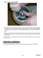
CLEANING, INSPECTION AND REPLACEMENT OF
DISSASEMBLED PARTS
Clean well and visually examine all the parts of the valve. Remove any burrs and sharp edges that
could damage the seals during reassembly. Thoroughly clean the piston bore to remove any
debris. Replace any damaged parts.

090090 R7
8
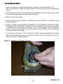
ASSEMBLY
1. Before assembly, apply lubricant to the Piston Bore, Piston (3) and Seals (11,12).
(We recommend the use of DuPont Krytox GPL-204 or Dow Corning #33 Silicone grease).
2. Refer to Fig 2 (detailed view of piston assembly) and Insert Piston into bore as shown and push
piston to bottom of bore.
3. Insert Stem Assembly as shown (1)
4. Insert Spring (5 for VR6035SQ / VR6030SQV and 6 for VR6035SQ / VR6035SQV) over Stem
Assembly (1).
5. Insert Washer (6 for VR6030SQ / VR6030SQV and 7 for VR6035SQ / VR6035SQV) into
Bearing (4 for VR6030SQ / VR6030SQV and 5 for VR6035SQ / VR6035SQV) and press
Bearing into piston bore over the Stem, as shown, against Spring Tension. The Bearing should
be firmly latched or otherwise held down against spring tension while the retaining ring is
assembled.
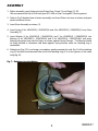
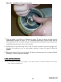
6. Referring to Figs 7-10, and using a screwdriver, gently separate the coils (fig. 2) of the retaining
ring (3) and feed the lowermost free end of the retaining ring (3) in to the groove on the valve
body (fig 10).
Fig 7 – Retaining ring installation

090090 R7
9
Fig 8 – Retaining ring installation
Fig 9 – Retaining ring installation

090090 R7
10
Fig 10 – Retaining ring installation
7. Hold the free end of the retaining ring (3) into the groove of the valve body and gradually rotate
the retaining ring (3) or valve whilst feeding the ring into groove (Figs 9 & 10). Keep feeding the
retaining ring (3) into the groove on the valve body until the ring is completely seated into the
groove.
8. Apply air to the inlet port to extend the stem. With the stem latched in the open position by
continuous application of air or by some other means, attach the poppet to the stem using the
latch pin clip.
9. Release the air, or the latching mechanism, and ensure that the poppet is firmly seated against
the valve seat.
DIXON BAYCO WARRANTY
For Warranty Information, please refer to the inside back cover of the latest Dixon Catalogue.

090090(fr) R7
1
Entretien & Mode d’emploi
pour
SOUPAPES À VAPEUR SÉQUENTIELLE À
AIR BAYCO
Numéro des pièces
E-U
Dixon Bayco USA
Chestertown, Maryland
Téléphone-2000
Fax: 410-778-4702
Sans frais : 800-355-1991
E-mail: dixonbayco@dixonvalve.com
www.dixonbayco.com
Canada:
Dixon Group Canada Limited
Innisfil (Barrie), Ontario
Téléphone: 705-436-1125
Fax: 705-436-6251
Sans frais :877-963-4966
E-mail: isales@dixongroupcanada.com
www.dixongroupcanada.com
Mexique:
Dixva, S. de R.L. de C.V.
Monterrey, N.L
Phone: 01-800-00-DIXON (34966)
Fax: 01-81-8354-8197
E-mail: contactenos@dixonvalve.com.mx
www.dixonvalve.com
Europe:
Dixon Group Europe Ltd
Preston, England
Téléphone: +44 (0)1772 323529
Fax: +44 (0)1772 314664
E-mail: enquiries@dixoneurope.co.uk
www.dixoneurope.co.uk
Asie Pacifique:
Dixon (Asia Pacific) Pty Ltd
Wingfield, South Australia
Téléphone: +61 8 8202 6000
Fax: +61 8 8202 6099
E-mail: enquiries@dixonvalve.com.au
www.dixonvalve.com.au
Pour vente & service contactez
VR6030SQ - Séquentielle – étanchéité de Baylast – pour trou d’homme standard de 16”
VR6035SQ - Séquentielle - étanchéité de Baylast - pour trou d’homme standard de
20”avec bride de 3” TTMA
VR6030SQV - Séquentielle – étanchéité de Viton - pour trou d’homme standard de 16”
VR6035SQV - Séquentielle - étanchéité de Viton - pour trou d’homme standard de
20”avec bride de 3” TTMA

090090(fr) R7
2
VR6030SQ / VR6030SQ: LISTE DE MATÉRIELS ET LISTE DE TROUSSE DE RÉPARATION
# QTÉ.
Numéro de
la pièce.
DESCRIPTION
TROUSSE DE RÉPARATION
VR6030RK1 VR6030RKV1 VR6030RK2 VR6030RK3 VR6030RKV3
1 1 400636 Assemblée de la tige
2 1 390823 Piston
O O O
3 1 111681 Anneau de retenu
O O
4 1 390822 Roulement
5 1 111680 goupille
O O
6 1 111679 Ressort
7 1 111683
Roulement d’étanchéité pour
roulement
8 2 111686 Bordure du joint
O (X2) O (X2) Y (X2)
9 1 111687 Bordure du joint
O O O
10
1 111008 Anneau de montage
11 1 111692 Joint torique #242
O O
12 1 341642 corps, 16"
13 1 341643 clapet
14
1 111691
Clapet du joint d’étanchéité
“Viton”
O O
1 112050
Clapet du joint d’étanchéité
“Baylast”
O O
15 1 111694 Bouchon pour tuyau de 1/4"
1
Fig
ure
2
-
Vue détaillée de l’assemblée
du piston
Fig
ure
1
-
Vue des pièces séparée
du VR6030SQ & VR6030SQV

090090(fr) R7
3
VR6035SQ / VR6035SQV: LISTE DE MATÉRIELS AND LISTE DE TROUSSE DE RÉPARATION
# QTÉ
Numéro de
la pièce
DESCRIPTION
TROUSSE DE RÉPARATION
VR6035RK1 VR6035RKV1 VR6035RK2 VR6035RK3 VR6035RKV3
1 1 400636
Assemblée de la tige
2 1 390823 Piston
Y Y Y
3 1 111681
Anneau de retenu
Y Y
4 1 111680 Goupille
Y Y
5 1 111679 Ressort
6 1 111683
Roulement de rondelle étanche
7 2 111686
Bordure du joint
Y (X2) Y (X2) Y (X2)
8 1 111687
Bordure du joint
Y Y Y
9
1 111678 Clapet du joint étanche “Viton”
Y
Y
1 112049 Clapet du joint étanche t “Baylast”
Y Y
10 1 341641 Clapet
11 8 111690 Boulon hexagone 3/8-16 UNC-2A x 5/8 lg
12 1 111689 Étanchéité
Y Y
13 8 110935 Rondelle de verrouillage, 3/8”
14 1 390822 Roulement
15 1 341640 Body, 20"
Fig
ure
3
-
Vue des pièces séparée du
VR6035SQ & VR6035SQV

090090(fr) R7
4
APPLICATIONS
Les soupapes à vapeur à air Bayco VR6030SQ / Vr6035SQ / et VR6030SQV / VR6035SQV
peuvent être utilisées pour des applications séquentielles ou non séquentielles. Pour les
applications séquentielles les soupapes ne permettront pas à l’air qui sert à l’actuation de
poursuivre son chemin à la soupape du compartiment suivant ou vers un autre mécanisme avant
que la soupape précédente soit ouverte.
LIGNE COMMUNE D’ACTIONNEMENT POUR SOUPAPE À VAPEUR
Une ligne commune d’actionnement permet aux soupapes à vapeur de rester ouvertes et aérés
indépendamment.
1. soupape à vapeur séquentielle
2. valve d’urgence
3. distributeur d’air
4. valve de contrôle centrale
5. alimentation d’air
1
5
2
2
2
2
4
3
1
1
Figure 4- Ligne commune d’actionnement pour soupape à vapeur
1

090090(fr) R7
5
COMPARTIMENT INDIVIDUEL D’ACTIONNEMENT POUR SOUPAPES À VAPEUR
Cet arrangement permet un contrôle individuel de chaque compartiment mais conserve la
ventilation du compartiment avant d’ouvrir la valve d’urgence. Pour faire fonctionner, ouvrez la
commande de soupape appropriée et activez la valve de contrôle centrale jusqu’à ce que la
soupape à vapeur et la valve d’urgence s’ouvre.
ACTIONNEMENT POUR SOUPAPE À VAPEUR NON SÉQUENTIELLE
Une opération non séquentielle du VR6030SQ / VR6035SQ et VR6030SQV / VR6035SQV peut
être atteinte en bouchant la sortie d’air séquentielle avec un bouchon de canalisation de ¼ NPT.
1. soupape à vapeur séquentielle
2. valve d’urgence
3. distributeur d’air
4. valve de contrôle centrale
5. alimentation d’air
1
1
1 1
5
2
2
2 2
4
3
Figure 5- Actionnement pour soupape à vapeur individuelle

090090(fr) R7
6
ENTRETIEN ET PIÈCES DE REMPLACEMENT POUR LES
SOUPAPES À VAPEUR SÉQUENTIELLES À AIR BAYCO
VR3060SQ / VR6035SQ ET VR6030SQV / VR6035SQV
Ces instructions sont recommandées et sont fournies pour un bon fonctionnement et un long
service des soupapes à vapeur à air VR6030SQ / VR6035SQ et VR6030SQV / VR6035SQV. Les
parties sont identifiées par le numéro des pièces sur le dessin d’assemblement et la liste des
pièces.
LIGNE D’AIR AVEC LUBRIFICATION D’HUILE
L’usage d’une ligne d’air avec lubrification d’air aidera pour assurer que le piston (2) et joints
d’étanchéité du piston (7,8 pour VR6035SQ et VR6035SQV & 8, 9 pour VR6030SQ et
VR6030SQV), sont lubrifiez en tout temps. Ceci diminuera les besoins d’entretiens et assura la
longévité de la soupape.
Figure 6 – Outils nécessaire pour l’entretien et le remplacement des pièces

090090(fr) R7
7
DÉMONTAGE
ATTENTION! DES LUNETTES DE SÉCURITÉS DOIVENT ÊTRE PORTÉES
DURANT LE DÉMONTAGE ET LE SERVICE.
1. Avec la pièce de façon sécuritaire et la sortie séquentielle d’air ploguée, appliquer une
pression d’air (approx. 20psi) dans le trou d’entrée d’air. Ceci permettra au clapet de
s’ouvrir et donnera accès aux pièces internes.
2. Retirez la goupille du loquet (4 pour VR6030SQ / VR6030SQV et 5 pour VR6035SQ /
VR6035SQV) du clapet (10 pour VR6035SQ / VR6035SQV & 13 pour VR6030SQ /
VR6030SQV) et la tige (1). Le clapet peut maintenant être retiré de l’assemblement.
3. Retirez la pression d’air de l’embouchure et permettez au clapet de se rétracter.
ATTENTION! LE ROULEMENT (5) EST TENU EN PLACE SOUS UNE
TENSION CONSIDÉRABLE D’UN RESSORT. ASSUREZ-VOUS
QUE LE ROULEMENT SOIT TENU EN PLACE DE FAÇON
SÉCURITAIRE AVANT D’ESSAYER DE RETIRER L’ANNEAU
DE RETENU (4).
4. Le roulement (4 pour VR6030SQ / VR6030SQV et 5 pour VR6035SQ / VR6035SQV) est
sécurisé avec un anneau de retenu à double boucle (4). Le démontage est fait en appuyant
sur le roulement contre la tension du ressort et en travaillant la partie supérieure de la
soupape hors de la rainure de la soupape.
5. Retirez le roulement (4 pour VR6030SQ / VR6030SQV et 5 pour VR6035SQ /
VR6035SQV), la rondelle (6 pour VR6030SQ / VR6030SQV et 7 pour VR6035SQ /
VR6035SQV), le ressort (5 pour VR6035SQ / VR6035SQV et 6 pour VR6030SQ /
VR6030SQV) et la tige d’assemblée (1).
ATTENTION! RECOUVREZ LA SOUPAPE DE FAÇON SÉCURITAIRE AVANT
D’ESSAYER DE DÉLOGER LE PISTON AVEC UNE PRESSION
D’AIR. SI VOUS NE LE FAITES PAS UNE ACCIDENT SÉRIEUX
POURRAIT EN RÉSULTER.
6. Ce piston est retiré en mettant une pression d’air (approx. 20psi) dans l’embouchure.
7. La soupape est maintenant complètement démontée.
NETTOYAGE, INSPECTION ET REMPLACEMENT DES
PIÈCES DÉSASSEMBLÉE.
Nettoyez bien et examinez visuellement toute les pièces de la soupape. Retirez toutes les bavures
et les bordures aiguisées qui pourraient endommager les joints d’étanchéités. Nettoyez
complètement le trou du piston et enlevez tous les débris. Remplacez toutes les pièces
endommagées.

090090(fr) R7
8
ASSEMBLEMENT
1. Avant l’assemblement, lubrifiez le trou du piston, le piston (3), et les étanchéités (11, 12)
(Nous recommandons l’usage du DuPont Krytox GPL-
204 ou Dow Corning #33 graisse de
silicone.
2. Faites référence à la figure 2 (vue détaillée de l’assemblement du piston) insérez le piston dans
le trou comme indiqué et pressez le piston au fond du trou.
3. Insérez la tige comme indiqué
4. Insérez le ressort (5 pour VR6035SQ / VR6030SQV et 6 pour VR6035SQ / VR6035SQV) sur la
tige d’assemblée (1).
5. Insérez la rondelle (6 pour VR6030SQ / VR6030SQV et 7 pour VR6035SQ / VR6035SQV) dans
le roulement (4 pour VR6030SQ / VR6030SQV et 5 pour VR6035SQ / VR6035SQV) et appuyer
le roulement sur le trou du piston par-dessus la tige, comme indiqué, contre la tension du
ressort. Le roulement devrait être sécurisé fermement contre la tension du ressort pendant que
l’anneau de retenu est assemblé.
6. Faites référence aux figures 7-10, en utilisant un tournevis, séparez délicatement les bobines
(figure 2) des anneaux de retenus (3) et passez la partie inférieure de l’anneau de retenu (3)
dans la rainure de la soupape (figure10).
Figure 7 – installation de l’anneau de retenu

090090(fr) R7
9
Figure 8 – installation de l’anneau de retenu
Figure 9 – installation de l’anneau de retenu

090090(fr) R7
10
Figure 10 – installation de l’anneau de retenu
7. Tenez en place le bout libre de l’anneau de retenu (3) dans la rainure et faites tourner
graduellement l’anneau de retenu (3) ou la soupape pendant que l’anneau rentre dans la
rainure (Figure 9 & 10). Continuez à rentrer l’anneau de retenu (3) jusqu’à ce que l’anneau soit
complètement placé dans la rainure de la soupape.
8. Appliquer de l’air pour étirer la tige. Avec la tige sécurisée en position ouverte en appliquant une
pression d’air continue ou par un autre moyen, attachez le clapet à la tige en utilisant la
goupille.
9. Relâchez la pression d’air ou le mécanisme du loquet, et assurez-vous que le clapet soit placé
fermement contre le siège de la soupape.
GARANTIE DIXON
Pour plus d’informations complètes sur la garantie, s’il vous plait se référer à la couverture intérieure de la dernière
page du dernier catalogue Dixon.
.
-
 1
1
-
 2
2
-
 3
3
-
 4
4
-
 5
5
-
 6
6
-
 7
7
-
 8
8
-
 9
9
-
 10
10
-
 11
11
-
 12
12
-
 13
13
-
 14
14
-
 15
15
-
 16
16
-
 17
17
-
 18
18
-
 19
19
-
 20
20


Dixon Air-Operated Sequential Vapor Valve (VR6030SQ & VR Vents Manuel utilisateur
- Taper
- Manuel utilisateur
- Ce manuel convient également à
dans d''autres langues
Documents connexes
-
 Dixon 6000/6200/6303/6400/6500/6500-Series Drop Elbow Seal Repair Kit Manuel utilisateur
-
 Dixon 2" Mobile Tank Vent Cap (200-PV-9) Manuel utilisateur
-
 Dixon 2180/3180-Series Dry Bulk Air Relief Valves Manuel utilisateur
-
 Dixon 1 1/4, 1 1/2 & 2 NPT Fuel Swivels SWMF125, 150 & 2 Manuel utilisateur
-
 Dixon Cam & Groove Dry Disconnect Lever Latch for 1-1/2" & 2" Manuel utilisateur
-
 Dixon In-Breathing/Out-Breathing Tank Vapor Vents Manuel utilisateur
-
 Dixon VR6100 Vapor Elbow Manuel utilisateur
-
 Dixon 1-1/2" & 2" DBA-Series Dry Disconnect Cam & Groove Adapter Repair Manuel utilisateur
-
 Dixon DB9000 Stationary Air Relief Valve Tester - Dry Bulk Manuel utilisateur
-
 Dixon 5204-Series API Valve Manuel utilisateur


