1 2 3
41 2 3
14
cdvi.com
cdvigroup.com
DGLP WLC - DGLP FN WLC - DGLPM WLC - DGLI WLC - DGLI F WLC
Lecteurs Proximité Wiegand
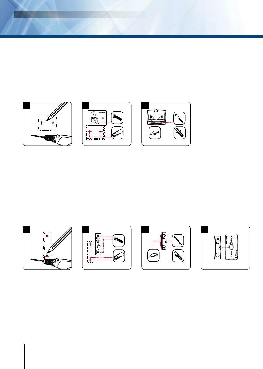
A l’aide du lecteur, prenez
les marques pour xer le
produit. Percez le support
de montage au niveau
des marques (Diamètres
de perçage préconisés :
plaque de xation =
4 mm et lecteur = 6 mm).
Grâce à votre schéma
de câblage, prévoyez
la sortie des câbles,
cachés dans la surface ou à
l’extérieur (moulure).
DGLI WLC
Placez les chevilles métal
dans les trous, connec-
tez les ls aux borniers
(voir schéma de câblage
page 4), puis xez le
lecteur avec les deux
vis DIAX
®
grâce à l’outil
DIAX
®
. N’oubliez pas de
placer la varistance au
niveau du système de
verrouillage (Voir page 2
«Rappels et préconisations»).
DGLP WLC et DGLPM WLC
Placez les chevilles plas-
tiques dans les trous,
connectez les ls aux bor-
niers (voir schéma de câ-
blage page 4), puis xez les
lecteurs avec les deux vis
à bois. Pour naliser l’ins-
tallation du lecteur, placez
les cache-vis. N’oubliez pas
de placer la varistance au
niveau du système de
verrouillage (Voir page 2
«Rappels et préconisations»).
A l’aide du lecteur, prenez
les marques pour xer le
produit. Percez le support
de montage au niveau
des marques (Diamètres
de perçage préconisés :
plaque de xation =
4 mm et lecteur = 6 mm).
Grâce à votre schéma
de câblage, prévoyez
la sortie des câbles,
cachés dans la surface ou à
l’extérieur (moulure).
DGLI F WLC
Placez les chevilles métal
dans les trous, connectez
les
ls aux borniers (voir sché-
ma de câblage page 4),
puis xez le lecteur avec
les deux vis DIAX
®
grâce
à l’outil DIAX
®
. N’oubliez
pas de placer la varistance
au niveau du système de
verrouillage (Voir page 2
«Rappels et préconisations»
).
DGLP FN WLC
Placez les chevilles plastiques
dans les trous, connectez les ls
aux borniers (voir schéma de
câblage page 4), puis xez les
lecteurs avec les deux vis à
bois.
Pour naliser l’instal-
lation du lecteur, placez les
cache-vis. N’oubliez pas
de placer la varistance au
niveau du système de
verrouillage (Voir page 2
«Rappels et préconisations»).
DGLP FN WLC (Option)
Pour ce lecteur, il existe
une plaque d’adaptation
qui se place entre la surface
de montage et le lecteur.
Cette plaque est non founie
(disponible sur demande).
Réf : DGLP FN WLC et DGLI F WLC
Après avoir vérié que le kit de montage est complet, vous allez pouvoir
procéder à l’installation nale de votre lecteur. Réunissez le matériel approprié
(Perçeuse, tournevis, mètre,...) et suivez les recommandations de montage
qui correspondent au lecteur que vous allez installer.
7] MONTAGE
Réf : DGLP WLC, DGLPM WLC et DGLI WLC
MANUEL D’INSTALLATION


