universal douglas 14049300 Manuel utilisateur
- Taper
- Manuel utilisateur

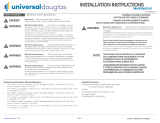
SAFETYWARNINGS IMPORTANT SAFETY INFORMATION
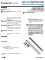
For installation in 4ft or 8ft strip-style luminaires, suitable for dry or damp locations,
with min. 4 inch width and 1-11/16 inch depth.
•(1) Preassembled Universal DouglasLED 4’ Primary Assembly Panel with:
•(1) Universal DouglasLED Lensed Module
•(1) Universal DouglasDriver
•Associated connectors and wires
•(1) Preassembled Universal Douglas LED4’ Secondary Assembly Panel with:
•(1) Universal DouglasLED Lensed Module
•(2) End Mounting Brackets
•(1) Universal DouglasMounting Bracket
NOTE: Consult your local authority regarding disposal or recycling procedures of removed
ballast and lamps.
UNPACKING THE KIT
Disconnect power before installation.
DANGER- RISQUE DE CHOC- COUPER L’ALIMENTATION AVANT L’INSTALLATION
LED Retrofit Assembly installation requires
knowledge of luminaires electrical systems. If not qualified, do not
attempt installation. Product must be installed in accordance with NEC
or your local electrical code. If you are not familiar with these codes and
requirements, contact a qualified electrician.
ATTENTION- Risque d’incendie ou de choc électrique. L’installation du kit upgrade
LED exige Ia connaissance des systèmes électriques pour luminaires. Si non qualifié,
ne tentez pas d’installation. Ce produit doit être installé conformément à NEC ou votre
code électrique local. Si vous n’êtes pas familier avec ces codes et ces exigences,
veuillezcontacter un électricien qualifié.
To prevent wiring damage or abrasion, do
not expose wires to the edge of sheet metal or any other sharp objects.
ATTENTION- Pour éviter les dégâts de câblage par l’abrasion, ne pas mettre en contact
les fils électriques avec des bords de tôle ou d’autres objets pointus.
Check the existing wiring for damage
before Installing upgrade assembly. Do not install if existing wires are
damaged.
ATTENTION- Risque d’incendie ou de choc électrique. Vérifier si le câblage existant
n’est pas endommagé avant l’installation du kit upgrade LED. Ne pas installer si des
fils sont endommagés. Luminaire wiring and electrical parts may
be damaged when drilling for installation of the LED upgrade assembly.
Check for enclosed wiring and components.
ATTENTION- Risque d’incendie ou de choc électrique. Câblage électriques peuvent
être endommagés Iors du perçage pour l’installation du kit upgrade LED. Vérifier les
fils et composants.
14049300 Rev B
Install this assembly only in luminaires that
have the construction features and dimensions shown in the photographs
and/or drawings.
ATTENTION- Risque d’incendie ou de choc électrique. lnstallez ce kit seulement dans
les luminaires qui ont les caractéristiques de construction et les dimensions dans les
photographies ou les dessins de Ia page suivante.
IL EST INTERDIT DE FAIRE OU DE MODIFIER UNE OUVERTURE DANS UN BOÎTIER
DE CÂBLAGE OU DE COMPOSANTS ÉLECTRIQUES AU COURS DE L’INSTALLATION
DU NÉCESSAIRE.
Page 1
www.universaldouglas.com Rev. 3/14/22Universal Lighting Technologies

14049300 Rev B
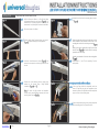
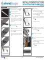
INSTALLATION
: Verify the fluorescent fixture is a 4ft or 8ft strip fixture
of appropriate dimensions as shown in . For
fixtures that are connected together in series on the
same branch circuit, identifythe section to be retrofitted.
: Disconnect power to the fixture.
: Remove the sockets from the mounting plate as shown
in .
: Replace mounting plate making sure that the holes are in the
same orientation as when removed. Insert the tab on the
mounting plate into the slot in the housing as shown in
.
Gently pry the housing outward with a large flat head screw
driver as shownin and insert the tab of the mounting
plateintotheslot in the housing.
Notethe correct orientation of the holes in the mounting plates
in .
: Repeat steps 5, 6, and 7 for the remaining 3 socket
mount plates.
: Place your finger behind the lampholder socket as
shown in Figure 8a and push the lampholder socket
towards the center of the light fixture until the lampholder
pops out of the socket mounting plate.
: Push the lampholder socket up and over the lampholder
socket mounting plate. See Figures 8b and 8c.
: Remove existing linear fluorescent lamps as shown in
. Dispose of lamps per local regulations.
: Locate the ¼-turn fasteners as shown in and
remove the cover panels on both strip light sections and
discard.
: Remove the socket mounting plate by gently prying
outward on the housing using a large flathead
screwdriver. and .
For some strip light models the lampholder
sockets can be removed without removing the socket
mounting plate. See steps - .
Page 2
USING EXISTING SOCKET BAR PLATES
www.universaldouglas.com Rev. 3/14/22Universal Lighting Technologies

14049300 Rev B
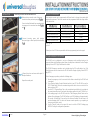
INSTALLATION
Page 3
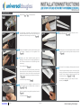
:Repeat steps and for all lampholders.
:Cut the branch circuit wires at the connection to the
fluorescent ballast leads in both strip light housings (if
ballasts exist in both housings) as shown in .
:Remove the ballast(s) by removing the mounting screw
and dispose of properly per local regulations. See
.
:Remove the Linear Retrofit Assembly from the
packaging. There are one of two panel assemblies: one
with a driver and module and one (LRA28 only) with a
module only.
For 4’ retrofits,skip to .
For 8’retrofits locate the panel with the module only.
Mount and position this assembly to the fixture section
furthest from the branch circuit splice connections with
the blue and red leads facing the center of the fixture -
See .
For LRA14 kits go straight to .
:Insert the ends of the lanyards at each end of the
panel assembly into the indicated holes as shown in
and .
Allow the assembly to hang by the lanyards as shown in
.
For LRA14 kits skip to .
:Route blue and red leads through the center of the
fuxture as shown in .
:Lift the panel such that the lanyards at each end feed
through the holes in which they were inserted, as shown
in .
:Touse the 1/4 - turnfasteners,firstremove theknockout.
Secure the panel assembly in place onto the strip light
housing, and fasten to the lampholder mounting plates
with the ¼-turn fasteners located at each end of the
assembly as shown in and .
For alternate mounting using the drill-point screws
provided, see Step 21A.
www.universaldouglas.com Rev. 3/14/22Universal Lighting Technologies

14049300 Rev B
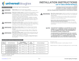
INSTALLATION
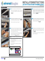
:Locate the remaining panel assembly with the driver.
Position the panel assembly for ease of connection
to the branch circuit wiring in the fixture as shown in
.
:Insert the ends of the lanyards at each end of the panel
assembly into the indicated holes as shown in
as done with the previous panel assembly.
Allow the assembly to hang by the lanyards.
: Locate the red and blue lead wires with the orange 3-
position push-in connectors attached and locate the
red and blue lead wires from the other tandem LRA
panel assembly previously installed.
Push the blue wire into the connector with the other blue
wires and the red wire into the connector with the other
red wires as shown in and .
:Locate the Luminaire Disconnect with the ground wire
connected. Secure the ground wire to the equipment
grounding conductor in the luminaire or to the luminaire
housing in accordance with the National Electrical Code
(NFPA 70). See . A ground screw is provided
with the kit if needed.
:From the branch circuit wires strip about 0.40 inches of
insulation. Insert the white branch circuit wire into the
white hole of the Luminaire Disconnect and the black
wire into the black hole. See .
:Lift the panel such that the lanyards at each end feed
through the holes in which they were inserted as
performed with the previous panel assembly as shown
in .
Secure the panel in place using the ¼-turn fasteners at
each end of the panel.
Blue ToothWirelessDimming Interface(BTLWE)
•ABlue tooth wirelessdimminginterface is connectedto the
end of one of the light bars.
•This is powered by the driver and connects to the driver’s
0-10V dimming leads
•Blue Tooth commands are received from a wireless
dimming control.
LED MODULE
LED DRIVER
BT-LWE
LED MODULE
SE RRATE D HEA D SC REW
GRO U N D S D RI VE R TO H OUS IN G
RED
BLUE
WHITE
BLACK
VIOLET
GREY
AUX 1
AUX 2
Page 4
www.universaldouglas.com Rev. 3/14/22Universal Lighting Technologies

14049300 Rev B
INSTALLATION
: Verify the fluorescent fixture is 8ft strip fixture of
appropriate dimensions as shown in .
:Disconnect power to the fixture.
:Remove fluorescent components including:
Examine all parts that are not intended to be
replaced by the retrofit assembly for damage and
replace any damaged parts prior to installation of
retrofit assembly.
:While panels are suspended make the following
connections:
Connect primary module ground lead to existing
fixture ground screw .
Ground lead position may be moved to alternate
location .
:Attach center bracket Locate large bracket at
center of 8 foot fixture .
Note: Be sure all existing wiring is above bracket.
Center bracketand usefixture as guideto bendto
correct width .
Once bracket us bent to size secure with #8 drill
point screw (supplied separately)on either side of
fixture.
:Attach end brackets.
Locate bracket align with end of fixture Ensure
tether hook features point inboard .
Center bracket width and use fixture as guide to
bend to correct width .
Once bracket us bent to size secure with #8 drill
point screw (supplied separately)on either side of
fixture .
Repeat at outer end of fixture.
:Suspended panels from tethers by inserting “T”
end of captive tether into hook features in brackets
at both ends of panel .
:Repeat steps 4-6 for secondary panel.
a. Lamps
b. Ballast cover Lamp holders & brackets
Ballast
Page 5
USING ADJUSTABLE MOUNTINGBRACKETS
www.universaldouglas.com Rev. 3/14/22Universal Lighting Technologies

14049300 Rev B
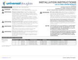
INSTALLATION DRIVER PROGRAMMING
BT-LWEEMERGENCY OPERATION
:Before making connection route all wire over
brackets to ensure panel seats properly ( ).
Connect red and blue leads from secondary panel
to orange push in connectors from driver)
and .
:Connect incoming power with luminaire
disconnect plug on driver input (black and white)
( ).
:Lift panel into place and secure with captive ¼
turn panel fasteners.
Repeat for second panel
Driver output currents can be programmed at different levels to change the system’s light
output and input power. The driver currents must be programmed within the ranges shown
in the table below:
Page 6
Contact your local ULT sales representative for driver programming tools and support.
The BT-LWE can be configured to act as an Emergency mode controller turning on its
connected fixture at full brightness when failure of normal power is detected. See the Douglas
Lighting Controls BTCC App Field Manual for details.
The BT-LWE Emergency operation can be tested using the iOS mobile device (e.g. iPod
Touch) that was used to commission the BT-LWE with the Douglas Lighting Controls BTCC
App (BTCC).
To test Emergency operation, perform the following steps:
1. Ensure the emergency circuit is connected to the fixture controlled by the BT-LWE and
is energized.
2. Use a Douglas Lighting Controls Bluetooth switch to turn OFF the BT-LWE, or use the
BTCC “Room Setup” tab on the commissioning mobile device to access control of the
device and turn it OFF.
3. Use the BTCC “System Setup” tab on the commissioning mobile device to navigate to
the commissioned devices list and select the settings cogwheel for the BT-LWE to test.
4. In the settings page for the BT-LWE, select the “Test Emergency Mode” button on the
bottom of the setting page. TheBT-LWEwill turn on to 100% brightness for approximately
30 seconds. Following the 30 second test, the fixture will remain ON and return to its
previous dimming state. The device will resume normal operation, e.g. responding to
occupancy and switch control.
5. Use the “Cancel” button in the upper left corner to exit the BT-LWE Settings page
WITHOUT writing the configuration parameters.
x= 35, 40, 50
y= 4or 5
LRAyC14-HL8xx-U-70LC D15CC55UNVPW-C 900mA
LRAyC14-ML8xx-U-42LC D10CC30UNVPW-C 1050mA
LRAyC28-HL8xx-U-12KC D21CC80UNVPW-C 1500mA
LRAyC28-HL8xx-U-85LC D21CC80UNVPW-C 750mA
LRAyC28-ML8xx-U-65LC D15CC55UNVPW-C 1500mA
USING ADJUSTABLE MOUNTINGBRACKETS
www.universaldouglas.com Rev. 3/14/22Universal Lighting Technologies
-
 1
1
-
 2
2
-
 3
3
-
 4
4
-
 5
5
-
 6
6


universal douglas 14049300 Manuel utilisateur
- Taper
- Manuel utilisateur
dans d''autres langues
Documents connexes
-
universal douglas LRA4P Manuel utilisateur
-
universal douglas LRK22-23Lyxx-U Manuel utilisateur
-
universal douglas LRKC24-40L8xx-U Manuel utilisateur
-
 universal douglas LR14T8-18L8xx-10DU-X Manuel utilisateur
-
 universal douglas T8 Manuel utilisateur
-
 universal douglas WL-TR40W22-A-D-AB-50 TRK Retrofit Kit Manuel utilisateur


