
EN
DE
FR
JA
ZH
M211887EN-D
Quick Guide
HPP270 Series PEROXCAP
â
Hydrogen Peroxide,
Humidity and Temperature Probes
HPP271 and HPP272

PUBLISHED BY
Vaisala Oyj
Vanha Nurmijärventie 21, FI-01670 Vantaa, Finland
P.O. Box 26, FI-00421 Helsinki, Finland
+358 9 8949 1
Visit our Internet pages at www.vaisala.com.
No part of this manual may be
reproduced, published or publicly
displayed in any form or by any
means, electronic or mechanical
(including photocopying), nor
may its contents be modified,
translated, adapted, sold or
disclosed to a third party without
prior written permission of the
copyright holder. Translated
manuals and translated portions
of multilingual documents are
based on the original English
versions. In ambiguous cases, the
English versions are applicable,
not the translations.
The contents of this manual are
subject to change without prior
notice.
Local rules and regulations may
vary and they shall take
precedence over the information
contained in this manual. Vaisala
makes no representations on this
manual’s compliance with the
local rules and regulations
applicable at any given time, and
hereby disclaims any and all
responsibilities related thereto.
This manual does not create any
legally binding obligations for
Vaisala towards customers or end
users. All legally binding
obligations and agreements are
included exclusively in the
applicable supply contract or the
General Conditions of Sale and
General Conditions of Service of
Vaisala.
This product contains software
developed by Vaisala or third
parties. Use of the software is
governed by license terms and
conditions included in the
applicable supply contract or, in
the absence of separate license
terms and conditions, by the
General License Conditions of
Vaisala Group.

Table of Contents
English............................................................................................................................ 5
Deutsch......................................................................................................................... 19
Français........................................................................................................................33
日本語.......................................................................................................................... 47
中文............................................................................................................................... 61
3

4 M211887EN-D

Product Overview
Vaisala PEROXCAPâ Hydrogen Peroxide, Humidity and Temperature Probe HPP270 series is
designed for demanding hydrogen peroxide bio-decontamination processes. The probes are
suitable for a variety of applications such as isolator, material transfer hatch, and room bio-
decontamination.
Hydrogen Peroxide, Humidity and Temperature Probe HPP271 provides measurement for
vaporized H
2
O
2
concentration.
Hydrogen Peroxide, Humidity and Temperature Probe HPP272 provides measurement for
vaporized H
2
O
2
concentration, relative saturation, relative humidity, and temperature.
The probe is not intended for safety level measurement.
The digital and analog output options include an RS-485 interface for Modbus communication
and two current output channels (4 … 20 mA).
HPP270 series probes can be connected to Vaisala Insight software for calibration,
configuration, diagnostics, and temporary online monitoring.
21 43
5
21 643
5
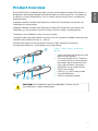
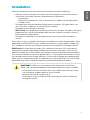
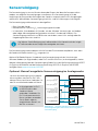
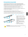
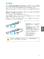
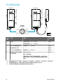
Figure 1 HPP271 (above) and HPP272
(below)
1 Yellow transport cap. Remove this cap
before using the probe.
2 Filter covering the sensor. The filter is
an essential part of the measurement
technology: do not remove the filter.
Filters are available as spare parts.
3 PEROXCAP sensor under the filter.
4 HPP271: H
2
O
2
probe.
HPP272: H
2
O
2
and humidity probe.
5 5-pin M12 connector.
6 HPP272: Temperature probe
Do not attempt to open the probe body. There are no user
serviceable parts inside the probe body.
CAUTION!
5
ENGLISH

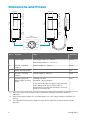
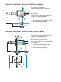
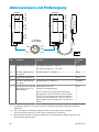
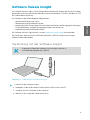
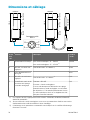
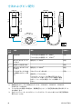
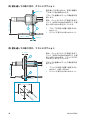
Dimensions and Pinout
1
5
34
2
M12/5
Male Connector
mm
118.3
44
Ø=18.5
70, Ø=4.8
38.5
Ø=30
400
22
Ø=16/18.5
118.3
44
Ø=18.5
38.5
Ø=30
22
Ø=16/18.5
HPP271 HPP272
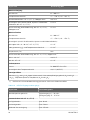
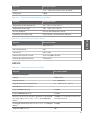
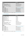
Pin # Function Notes Wire Color
1)
1 Power supply With digital output: 15 ... 30 VDC
With analog output: 15 ... 25 VDC
2)
Brown
2 RS-485- or analog
output 2
Current output: 4 … 20 mA
3)
White
3 Power and signal GND Blue
4 RS-485+ or analog
output 1
Current output: 4…20 mA
3)
Black
5 Output control and
purge trigger in analog
mode
Floating = RS-485
Grounded = Analog outputs
If you want to be able to trigger a purge manually
in the analog mode, do not connect pin #5
permanently to ground, but instead, use a relay or
similar to control the pin.
Grey
1) Wire colors apply to the following cables: 254294SP, 254295SP, 254296SP, 254297SP,
244669SP
2) When using analog outputs, it is recommended to use a low supply voltage to minimize self-
heating.
3) The ordered parameters and scaling are shown in the calibration certificate delivered with
the probe.
6 M211887EN-D

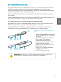
Installation
When you choose the installation location for the probe, consider the following:
• Choose a location that represents the environment and process you want to measure.
Some factors may make a location unrepresentative of the process:
• Heat sources
• Materials that absorb H
2
O
2
, such as several plastics, rubbers and sealing materials
• Limited air
flow
• The probes withstand bio-decontamination process conditions. For signal cables, you
must verify their suitability in the installation environment.
• The probes withstand high air
flow rates.
• HPP272 only: For condensation monitoring with relative saturation, consider installing the
probe close to a surface where condensation may form (typically, on cooler surfaces in
the bio-decontaminated space).
• The probe is intended for use in atmospheric pressure. Do not install the probe in a
vacuum.
When there is H
2
O
2
in the probe's environment, the probe must always be powered on. When
powered on, the PEROXCAP sensor is heated, which permits using the probe in condensing
H
2
O
2
conditions, maintains measurement performance, and lengthens the probe's lifetime.
HPP272 only: Accurate relative humidity (RH) and relative saturation (RS) measurement
requires both humidity and temperature data from the same environment. Install the main
body of the probe (H
2
O
2
and humidity measurement) and the attached temperature probe in
the same measurement environment, approximately 6 ... 10 cm apart from each other, so that
the conditions are the same for both elements. Do not install the temperature probe directly
above the H
2
O
2
and humidity probe, as moderate heat rising up from the H
2
O
2
and humidity
probe body may
aect the ambient temperature around the temperature probe.
The filter is an essential part of the measurement. If the filter is
broken, dirty, or removed altogether, measurement does not work as intended.
• Do not touch the
filter with bare hands. If you need to touch the filter, always
use clean gloves (rubber, cotton or similar material).
• Keep the
filter free of any grease or oil.
• Do not touch any parts under the filter. Touching parts under the filter may
damage the sensors.
CAUTION!
7
ENGLISH

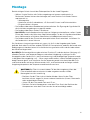
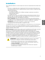
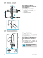
Example: Installation Through a Wall, Gland Option
60 ... 100 mm
≤ 6 mm
Ø 40 mm
Ø 8 mm
1
2
40 mm
(recommended)
A through-wall installation is
recommended especially in very harsh
processes.
Seal the lead-throughs on the metal body
of the probes.
The figure shows an example installation
using Vaisala spare part glands
(HPP272MOUNTINGSET1).
1 Nut for tightening the probe in place
2 Nut for mounting the gland
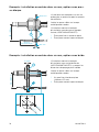
Example: Installation Through a Wall, Flange Option
Ø 5 mm
Ø 27 mm
1
2
60 ... 100 mm
≤ 4 mm
40 mm
Ø 8 mm
The figure shows an example installation
using Vaisala spare part flange
(HPP272MOUNTINGSET2), including the
drilling dimensions for the flange.
Seal the lead-throughs on the metal body
of the probes.
1 Screws for tightening the flange in
place (4 pcs, Ø 5 mm)
2 Nut for mounting the gland
8 M211887EN-D

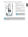
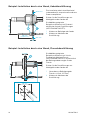
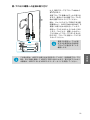
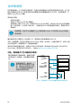
Example: Installation Entirely in Process Environment
Ø 5.5 mm
68 mm
5.5 mm
Mount the H
2
O
2
and humidity probe from
the probe body.
Mount the temperature probe from the
metal body. Note that the temperature
sensor is at the tip of the temperature
probe.
The figure shows an example installation
using Vaisala spare part wall mounting set
(HPP272WALLMOUNT).
Let the signal cable hang loosely so that it
makes a bend. This prevents condensing
water from running to the probe along the
cable. Do not hang the probe by the signal
cable.
Make sure the signal cable you
use is suitable for your bio-
decontamination process.
The examples in this section show how to install HPP272. The same instructions
apply to HPP271 installation with the exception of the external temperature probe.
For more information on installation accessories, see the HPP271 and HPP272
User Guides.
9
ENGLISH

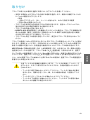
Chemical Purge
Chemical purge is a 4-minute process where the sensors are heated to remove possible
contamination. The purge is essential for the long-term performance and accuracy of the
probe in demanding H
2
O
2
environments. During the purge, H
2
O
2
and H
2
O measurements are
not available.
The purge is automatically performed:
• At probe start-up.
• After an RH for H
2
O
2
adjustment is made.
• At intervals (default 24 hours, configurable between 1 hour ... 1 week using Vaisala Insight
software, Modbus, or Indigo transmitters). Purge is postponed by 30 minutes if H
2
O
2
is
present or ambient humidity is not steady.
If required, you can also enable purge during H
2
O
2
exposure with the Insight PC
software or an Indigo transmitter.
Purge is recommended at least every 24 hours of powered-on time, even if the probe has not
been continuously exposed to H
2
O
2
.
Optional: if needed, you can also trigger a purge at any time with Vaisala Insight software,
Modbus (in digital mode) or pin #5 on the M12 connector (in analog mode).
For more information on the chemical purge, see HPP271 User Guide in English M211888EN and
HPP272 User Guide in English M211972EN available at www.vaisala.com/HPP270.
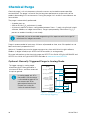
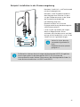
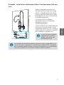
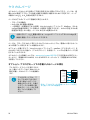
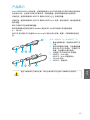
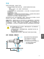
Optional: Manually Triggered Purge in Analog Mode
To trigger a purge in analog mode,
disconnect pin #5 from ground for a
minimum of 50 ms, and then reconnect
the pin to ground.
In analog mode, pin #5 in
the probe's M12 connector
is connected to ground. Do
not connect pin #5 to
ground permanently, but
instead, use a relay or
similar to control the pin.
PLC
DC power
supply
IN+ Current input
IN-
IN+ Current input
IN-
Relay/switch
control
+
-
Pin #1
(Power supply)
Pin #2
(Analog output 2)
Pin #3
(Power and signal
GND)
Pin #4
(Analog output 1 )
Pin #5
(Output control
and purge trigger
in analog mode)
HPP270 series
probe
Figure 2 Example wiring in analog mode to enable
manual purge triggering
10 M211887EN-D

Vaisala Insight Software
Vaisala Insight software is a configuration software for Indigo-compatible probes. The
supported operating systems are Windows 7 (64-bit), Windows 8.1 (64-bit), and Windows 10
(64-bit).
With the Insight software, you can:
• See device information and status.
• See real-time measurement.
•
Configure serial communication settings, purge settings, filtering factor, and analog
output parameters and scaling.
• Calibrate and adjust the device.
Download Vaisala Insight software at www.vaisala.com/insight.
The probe can be connected to Vaisala Insight software using a Vaisala USB cable (no.
242659).
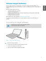
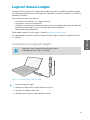
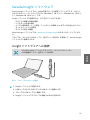
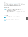
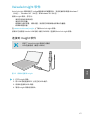
Connecting to Insight Software
• Computer with Vaisala Insight software installed
• USB connection cable (no. 242659)
Figure 3 Connecting Probe to Insight
1. Open the Insight software.
2. Connect the USB cable to a free USB port on the PC.
3. Connect the probe to the USB cable.
4. Wait for Insight software to detect the probe.
11
ENGLISH

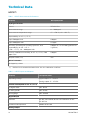
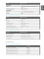
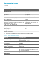
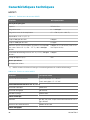
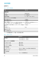
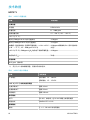
Technical Data
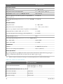
HPP271
Table 1 HPP271 Measurement Performance
Property Description/Value
Hydrogen Peroxide
Sensor PEROXCAPâ
Measurement range 0 ... 2000 ppm
Measurement temperature range +5 ... +50 °C (+41 ... +122 °F)
Repeatability at +25 °C (+77 °F)
up to 500 ppm H
2
O
2
±10 ppm
up to 1000 ppm H
2
O
2
±15 ppm
Accuracy (including non-linearity, hysteresis, and
repeatability) at +10 ... +25 °C
(+50 … +77 °F) , 10 ... 2000 ppm H
2
O
2
±10 ppm or 5 % of reading (whichever
is greater)
Factory calibration uncertainty, at +25 °C (+77 °F), 500
ppm H
2
O
2
1
±10 ppm
Response time (T
63
) 70 s
Other Parameters
H
2
O ppm by volume
1) Defined as ±2 standard deviation limits. See also calibration certificate.
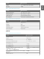
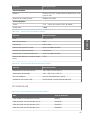
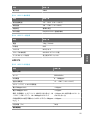
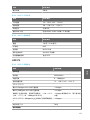
Table 2 HPP271 Inputs and Outputs
Property Description/Value
Operating voltage Digital output: 15 ... 30 VDC
Analog output: 15 ... 25 VDC
Current Consumption at +25 °C (+77 °F)
In digital mode Max. 10 mA
In analog mode Max. 50 mA
During purge Max. 250 mA
Digital Output
Interface RS-485, not isolated; do not use termination on the
RS-485 line
Communication protocol Modbus RTU v.1.02
Analog Output
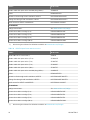
12 M211887EN-D

Property Description/Value
Outputs 2 × 4 ... 20 mA 3-wire current outputs
Max. load 500 Ω
Table 3 HPP271 Operating Environment
Property Description/Value
Operating temperature +0 ... +70 °C (+32 ... +158 °F)
Storage temperature -20 ... +70 °C (-4 ... +158 °F)
Ambient pressure Normal atmospheric pressure
EMC compliance EN/IEC 61326-1, Industrial Environment
Table 4 HPP271 Mechanical Specifications
Property Description/Value
Weight 110 g (3.88 oz)
IP rating IP65
Connector M12/5 male
Probe body material AISI316L stainless steel
Filter cap material Porous PTFE
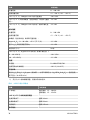
HPP272
Table 5 HPP272 Measurement Performance
Property Description/Value
Hydrogen Peroxide
Sensor PEROXCAPâ
Measurement range 0 ... 2000 ppm
Measurement temperature range +5 ... +50 °C (+41 ... +122 °F)
Repeatability at +25 °C (+77 °F)
up to 500 ppm H
2
O
2
±10 ppm
up to 1000 ppm H
2
O
2
±15 ppm
Accuracy (including non-linearity, hysteresis, and
repeatability) at +10 ... +25 °C
(+50 … +77 °F) , 10 ... 2000 ppm H
2
O
2
±10 ppm or 5 % of reading (whichever
is greater)
Factory calibration uncertainty, at +25 °C (+77 °F), 500
ppm H
2
O
2
1)
±10 ppm
Response time (T
63
) 70 s
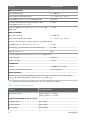
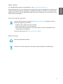
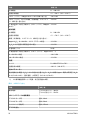
13
ENGLISH

Property Description/Value
Relative Saturation
Measurement range 0 ... 100 %RS
Measurement temperature range +5 ... +50 °C (+41 ... +122 °F)
Repeatability at +25 °C (+77 °F), 500 ppm H
2
O
2
±0.5 %RS
Accuracy (including non-linearity, hysteresis, and
repeatability) at +25 °C (+77 °F):
±4 %RS
Factory calibration uncertainty, at +25 °C (+77 °F), 500
ppm H
2
O
2
1)
±2 %RS
Relative Humidity
Measurement range 0 ... 100 %RH
Measurement temperature range +5 ... +70 °C (+41 ... +158 °F)
Accuracy (including non-linearity, hysteresis, and repeatability):
at 0 ppm H
2
O
2
, 0 ... 90 %RH, +25 °C (77 °F) ±1 %RH
over full H
2
O
2
and temperature measurement range: ±2 %RH
Response time (T
63
) 20 s
Factory calibration uncertainty, at +25 °C (77 °F), 0 ppm H
2
O
2
:
1)
at 0 … 40 %RH ±0.6 %RH
at 40 … 95 %RH ±1 %RH
Temperature
Sensor Pt-1000 RTD Class F0.1
Accuracy over temperature range ±0.2 °C (±0.36 °F)
Other Parameters
Absolute H
2
O
2
and H
2
O, H
2
O ppm by volume, water vapor saturation pressure (H
2
O and H
2
O
+H
2
O
2
), dew point temperature, vapor pressure (H
2
O and H
2
O
2
)
1) Defined as ±2 standard deviation limits. See also calibration certificate.
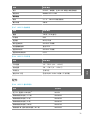
Table 6 HPP272 Inputs and Outputs
Property Description/Value
Operating voltage Digital output: 15 ... 30 VDC
Analog output: 15 ... 25 VDC
Current Consumption at +25 °C (+77 °F)
In digital mode Max. 10 mA
In analog mode Max. 50 mA
During purge Max. 250 mA
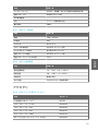
14 M211887EN-D

Property Description/Value
Digital Output
Interface RS-485, not isolated; do not use termination on the
RS-485 line
Communication protocol Modbus RTU v.1.02
Analog Output
Outputs 2 × 4 ... 20 mA 3-wire current outputs
Max. load 500 Ω
Table 7 HPP272 Mechanical Specifications
Property Description/Value
Weight 130 g (4.58 oz)
IP rating IP65
Connector M12/5 male
Probe body material AISI316L stainless steel
Filter cap material Porous PTFE
Temperature probe material AISI316L stainless steel
Temperature probe cable material PTFE
Table 8 HPP272 Operating Environment
Property Description/Value
Operating temperature +0 ... +70 °C (+32 ... +158 °F)
Storage temperature -20 ... +70 °C (-4 ... +158 °F)
Ambient pressure Normal atmospheric pressure
EMC compliance EN/IEC 61326-1, Industrial Environment
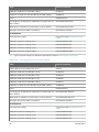
Accessories
Table 9 HPP271 Spare Parts and Accessories
Name Order Code
USB cable for PC connection
1)
242659
Probe cable with open wires (1.5 m) 254294SP
Probe cable with open wires (3 m) 254295SP
Probe cable with open wires (5 m) 254296SP
Probe cable with open wires (10 m) 254297SP
15
ENGLISH

Name Order Code
Probe cable with open wires and 90° plug (0.6 m) 244669SP
Filter DRW246363SP
Gland set for through-wall installation, HPP271 HPP271MOUNTINGSET1
Flange for through-wall installation, HPP271 HPP271MOUNTINGSET2
Wall mount for HPP271 and HPP272 HPP272WALLMOUNT
Transmitters
Indigo transmitters See www.vaisala.com/indigo
Connection cable to Indigo (1 m) INDIGOCABLEHD1M5
Connection cable to Indigo (3 m) INDIGOCABLEHD3M
Connection cable to Indigo (5 m) INDIGOCABLEHD5M
Connection cable to Indigo (10 m) INDIGOCABLEHD10M
1) Vaisala Insight software for Windows available at www.vaisala.com/insight
Table 10 HPP272 Spare Parts and Accessories
Name Order Code
USB cable for PC connection
1)
242659
Probe cable with open wires (1.5 m) 254294SP
Probe cable with open wires (3 m) 254295SP
Probe cable with open wires (5 m) 254296SP
Probe cable with open wires (10 m) 254297SP
Probe cable with open wires and 90° plug (0.6 m) 244669SP
Filter DRW246363SP
Gland set for through-wall installation, HPP272 HPP272MOUNTINGSET1
Flange for through-wall installation, HPP272 HPP272MOUNTINGSET2
Wall mount for HPP271 and HPP272 HPP272WALLMOUNT
Transmitters
Indigo transmitters See www.vaisala.com/indigo
Connection cable to Indigo (1 m) INDIGOCABLEHD1M5
Connection cable to Indigo (3 m) INDIGOCABLEHD3M
Connection cable to Indigo (5 m) INDIGOCABLEHD5M
Connection cable to Indigo (10 m) INDIGOCABLEHD10M
1) Vaisala Insight software for Windows available at www.vaisala.com/insight
16 M211887EN-D

Warranty
For standard warranty terms and conditions, see www.vaisala.com/warranty.
Please observe that any such warranty may not be valid in case of damage due to normal wear
and tear, exceptional operating conditions, negligent handling or installation, or unauthorized
modifications. Please see the applicable supply contract or Conditions of Sale for details of the
warranty for each product.
Technical Support
Contact Vaisala technical support at helpdesk@vaisala.com. Provide at least the
following supporting information:
• Product name, model, and serial number
• Name and location of the installation site
• Name and contact information of a technical person who can provide further
information on the problem
For more information, see www.vaisala.com/support.
Recycling
Recycle all applicable material.
Follow the statutory regulations for disposing of the product and packaging.
17
ENGLISH

18 M211887EN-D

Produktübersicht
Die Vaisala PEROXCAPâ Wasserstoperoxid-, Feuchte- und Temperatursonde der Baureihe
HPP270 wurde für anspruchsvolle Wasserstoperoxid-Biodekontaminationsprozesse
entwickelt. Die Sonden sind für unterschiedliche Anwendungen wie Isolatoren, Materialluken
sowie zur Biodekontamination von Räumen geeignet.
Die
Wasserstoperoxid-, Feuchte- und Temperatursonde HPP271 misst die Konzentration von
H
2
O
2
-Dampf.
Die
Wasserstoperoxid-, Feuchte- und Temperatursonde HPP272 misst die Konzentration von
H
2
O
2
-Dampf sowie relative Sättigung, relative Feuchte und Temperatur.
Die Sonde wurde nicht für sicherheitsrelevante Messungen entwickelt.
Die Optionen für Digital- und Analogausgänge umfassen eine RS-485-Schnittstelle für die
Modbus-Kommunikation und zwei Stromausgangskanäle (4 … 20 mA).
Sonden der Baureihe HPP270 können mit der Software Vaisala Insight für Kalibrierung,
Konfiguration, Diagnose und temporäre Onlineüberwachung verbunden werden.
21 43
5
21 643
5
Abbildung 4 HPP271 (oben) und HPP272
(unten)
1 Gelbe Transportabdeckung. Entfernen
Sie diese Abdeckung vor Verwendung
der Sonde.
2 Den Sensor abdeckender Filter. Der
Filter ist eine unverzichtbare
Komponente der Messtechnik.
Entfernen Sie den Filter nicht. Filter
sind als Ersatzteil erhältlich.
3 PEROXCAP-Sensor unter dem Filter.
4 HPP271: H
2
O
2
-Sonde.
HPP272: H
2
O
2
- und Feuchtesonde.
5 5-poliger M12-Anschluss.
6 HPP272: Temperatursonde
Versuchen Sie nicht, den Sondenkörper zu önen. Es gibt keine
vom Benutzer zu wartenden Teile im Inneren des Sondenkörpers.
ACHTUNG
19
DEUTSCH

Abmessungen und Pinbelegung
5-poliger
M12-Stecker
mm
118,3
44
Ø=18,5
70, Ø=4,8
38,5
Ø=30
400
22
Ø=16/18,5
118,3
44
Ø=18,5
38,5
Ø=30
22
Ø=16/18,5
HPP271 HPP272
Pin Funktion Hinweise Leiterfar-
be
1)
1 Spannungsversorgung Mit Digitalausgang: 15 ... 30 V DC
Mit Analogausgang: 15 ... 25 V DC
2)
Braun
2 RS-485- oder Analog-
ausgang 2
Stromausgang: 4 … 20 mA
3)
Weiß
3 Strom und Signalmasse Blau
4 RS-485+ oder Analog-
ausgang 1
Stromausgang: 4…20 mA
3)
Schwarz
5 Ausgangssteuerung und
Reinigungsauslöser im
Analogmodus
Potenzialfrei = RS-485
Geerdet = Analogausgänge
Wenn Sie die Sensorreinigung im Analogaus-
gangsmodus manuell auslösen möchten, dürfen
Sie Pin 5 nicht permanent mit Masse verbinden,
sondern müssen stattdessen ein Relais oder ein
vergleichbares Bauteil verwenden, um den Pin zu
steuern.
Grau
1) Leiterfarben gelten für die folgenden Kabel: 254294SP, 254295SP, 254296SP, 254297SP,
244669SP
2) Bei Verwendung von Analogausgängen wird die Verwendung einer niedrigen
Speisespannung empfohlen, um die Eigenerwärmung zu minimieren.
3) Die bestellten Parameter und deren Skalierung sind im Kalibrierzertifikat angegeben, das
mit der Sonde geliefert wird.
20 M211887EN-D
La page est en cours de chargement...
La page est en cours de chargement...
La page est en cours de chargement...
La page est en cours de chargement...
La page est en cours de chargement...
La page est en cours de chargement...
La page est en cours de chargement...
La page est en cours de chargement...
La page est en cours de chargement...
La page est en cours de chargement...
La page est en cours de chargement...
La page est en cours de chargement...
La page est en cours de chargement...
La page est en cours de chargement...
La page est en cours de chargement...
La page est en cours de chargement...
La page est en cours de chargement...
La page est en cours de chargement...
La page est en cours de chargement...
La page est en cours de chargement...
La page est en cours de chargement...
La page est en cours de chargement...
La page est en cours de chargement...
La page est en cours de chargement...
La page est en cours de chargement...
La page est en cours de chargement...
La page est en cours de chargement...
La page est en cours de chargement...
La page est en cours de chargement...
La page est en cours de chargement...
La page est en cours de chargement...
La page est en cours de chargement...
La page est en cours de chargement...
La page est en cours de chargement...
La page est en cours de chargement...
La page est en cours de chargement...
La page est en cours de chargement...
La page est en cours de chargement...
La page est en cours de chargement...
La page est en cours de chargement...
La page est en cours de chargement...
La page est en cours de chargement...
La page est en cours de chargement...
La page est en cours de chargement...
La page est en cours de chargement...
La page est en cours de chargement...
La page est en cours de chargement...
La page est en cours de chargement...
La page est en cours de chargement...
La page est en cours de chargement...
La page est en cours de chargement...
La page est en cours de chargement...
La page est en cours de chargement...
La page est en cours de chargement...
La page est en cours de chargement...
La page est en cours de chargement...
-
 1
1
-
 2
2
-
 3
3
-
 4
4
-
 5
5
-
 6
6
-
 7
7
-
 8
8
-
 9
9
-
 10
10
-
 11
11
-
 12
12
-
 13
13
-
 14
14
-
 15
15
-
 16
16
-
 17
17
-
 18
18
-
 19
19
-
 20
20
-
 21
21
-
 22
22
-
 23
23
-
 24
24
-
 25
25
-
 26
26
-
 27
27
-
 28
28
-
 29
29
-
 30
30
-
 31
31
-
 32
32
-
 33
33
-
 34
34
-
 35
35
-
 36
36
-
 37
37
-
 38
38
-
 39
39
-
 40
40
-
 41
41
-
 42
42
-
 43
43
-
 44
44
-
 45
45
-
 46
46
-
 47
47
-
 48
48
-
 49
49
-
 50
50
-
 51
51
-
 52
52
-
 53
53
-
 54
54
-
 55
55
-
 56
56
-
 57
57
-
 58
58
-
 59
59
-
 60
60
-
 61
61
-
 62
62
-
 63
63
-
 64
64
-
 65
65
-
 66
66
-
 67
67
-
 68
68
-
 69
69
-
 70
70
-
 71
71
-
 72
72
-
 73
73
-
 74
74
-
 75
75
-
 76
76


dans d''autres langues
- Deutsch: Vaisala HPP270 Benutzerhandbuch
- 日本語: Vaisala HPP270 ユーザーマニュアル
Documents connexes
-
Vaisala HMP50 Manuel utilisateur
-
Vaisala MMT162 Manuel utilisateur
-
-
-
-
-
-
-
-
Autres documents
-
ProMinent DULCOTEST PAA 1-mA-200 ppm Operating Instructions Manual
-
Grundfos Conex DIA-1 Installation And Operating Instructions Manual
-
Mettler Toledo InPro6000G Series Gas Phase Oxygen Sensors Mode d'emploi
-
-
Elcometer 456 Manuel utilisateur