La page est en cours de chargement...

Installation Instructions | Installationsanleitung | Notice d’installation
Instrucciones de instalación | Istruzioni per l’installazione
Minebea Intec Relay Box YSB01
Relay card with IP66-protected housing, with 6 relay outputs and one electrically
isolated input
Minebea Intec Relaisbox YSB01
Relaiskarte im IP66-Gehäuse mit 6 Relaisausgängen und einem galvanisch
getrennten Eingang
Boîtier relais Minebea Intec YSB01
Carte relais dans le boîtier IP66 avec 6 sorties relais et une entrée isolée
électriquement
Caja de relé YSB01 Minebea Intec
Tarjeta de relé en caja con grado de protección IP66, 6 salidas y una entrada
separada galvánicamente.
Minebea Intec Scatola relè YSB01
Scheda relè nell’alloggiamento IP66 con 6 uscite relè e un ingresso isolato
elettricamente
98647-003-47
98647-003-47

Installation Instructions | Installationsanleitung 3
English - page 3
Deutsch - Seite 13
Français – page 23
Español – página 33
Italiano - pagina 43

Installation Instructions | Installationsanleitung 3
Contents
3 Contents
3 Warnings and Safety Precautions
4 Intended Use
6 Installation
7 Wiring Diagram for Operating
Mode 1
8 Wiring Diagram for Operating
Mode 2
9 Cabling Diagram for Optional
YCC02-RELAIS01 Cable
10 Cabling Diagram for Optional
YCC02-RELAIS02 Cable
11 Cabling Diagram for Optional
YCCDI-03M5 Cable
12 Specifications
– Do not use this equipment in hazar-
dous areas/locations.
– Disconnect equipment from power
before opening the relay box.
– When using an external power supply,
the surge capacity in accordance with
EN 61326 must be ensured by the
power source.
– If the YSB01 is connected to
a power source that is not
safely electrically isolated from
the mains supply (IEC 364-4-41), the
enclosed warning label indicating ha-
zardous voltage must be affixed to the
YSB01 in a highly visible location.
– Non-permissible operating status:
If the relay module is connected to a
power supply and the control device
(scale or indicator) is not, this may
result in an undefined relay status. For
this reason, it is essential to make sure
both the relay module and the control
device are connected to power.
Warnings and
Safety Precautions

4 Installation Instructions | Installationsanleitung Installation Instructions | Installationsanleitung 5
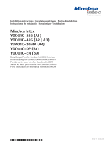
Intended Use
Servo-components
UNI_IN 6 relay outputs
Power supply
provided by
customer
(+10 V to
+30 V DC)
The YSB01 relay box is
designed for connecting
peripheral devices with
higher output levels to
a Minebea Intec control
device (Combics 2/3,
QC..., QCT01, FC...,
SEB..., SEBT01).
The relay box can be
operated in either of two
modes:
– Operating mode 1 (non-
encoded data):
Up to 4 output relays
are switched directly
by 4 control signals.
An electrically isolated
(optoisolated) input is
available.
– Operating mode 2 (enco-
ded data):
Up to 5 output relays
are switched by com-
binations of 3 signals
from the control device
(as with the Combics
“Classification” applica-
tion, for example). One
output relay is switched
directly by a control
signal. An electrically
isolated (optoisolated)
input is available.
Relay box YSB01
UNI_IN 4 signal lines
Power supply
Control device
(scale, indicator)

Installation Instructions | Installationsanleitung 5
The closed status of an output relay is
indicated by an LED.
The YSB01 relay box has been prepared
at the factory for installation on a top-
hat rail.
The relay outputs are to be wired
directly to the control elements.
The connection of the relay box to the
control device (scale or indicator) is to
be performed by the customer using
one of the following cables (available
from Minebea Intec):
– YCC02-RELAIS01 for connection to
Combics (CISL2/3, CAISL2/3)
– YCC02-RELAIS02 for connection to
Combics (CIS2/3, CAIS2/3)
– YCCDI-03M5 for connection to QC...,
QCT01, FC..., SEB..., SEBT01
Opto-input with
separate power supply Relay outputs
(connections: A1 to A10)
Control device connection DIP switch LED Power supply
(scale, indicator) (connections: C1 to C4)
(connections: B1 to B6)

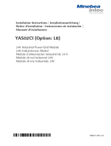
6 Installation Instructions | Installationsanleitung Installation Instructions | Installationsanleitung 7
Installation
§ Disconnect the YSB01 relay box from
power before opening the housing.
§ To open the relay box, remove the four
screws from the cover plate.
§ Installing the cable gland and cable:
– Prepare the cable opening by breaking
out the pre-punched M20 chip.
– Guide the enclosed cable gland
(M20 x 1.5) through the opening and
secure it inside the housing with the
counternut (1).
– Route the cable (2) through the cable
gland. Tighten the screw-down nut
(3) until the sealing clamp (4) forms a
slight ridge between screw-down nut
and cable.
§ Mount the cable on the relay card in
accordance with the relevant wiring
diagram (see below).
12
3
4

Installation Instructions | Installationsanleitung 7
Wiring Diagram for Operating Mode 1
To operate the relay box in Operating Mode 1 (non-encoded data), all DIP switches (1
through 7) must be open (“Off”).
A10 Ground (customer installation)
A9 Supply voltage (customer installation)
A1 UNI-IN
Less than (<) 2
Equal to (=) 3
Greater than (>) 4
Set 5
B6 Ground (from control device) Power supply C1
B5 UNI (from control device)
B4 MINOR: Less than (<)
B3 PARES: Equal to (=) Ground C3
B2 MAJOR: Greater than (>) (from control device)
B1 SET
Combics application: “Basic Filling”
Coarse flow: Control signal: Less than (<) Relay 2
Fine flow: Control signal: Equal to (=) Relay 3
Within tolerance: Control signal: Greater than (>) Relay 4
Filling active: Control signal: Set Relay 5

8 Installation Instructions | Installationsanleitung Installation Instructions | Installationsanleitung 9
Wiring Diagram for Operating Mode 2
To operate the relay box in Operating Mode 2 (encoded data), DIP switches 1 through 3
and 5 through 7 must be open (“Off”) and DIP switch 4 closed (“On”).
B6 Ground (from control device) Power supply C1
B5 UNI (from control device)
B4 MINOR: Less than (<)
B3 PARES: Equal to (=) Ground C3
B2 MAJOR: Greater than (>) (from control device)
B1 SET
A10 Ground (customer installation)
A9 Supply voltage (customer installation)
A1 UNI-IN
Less than (<) 2
Less than (<) + Equal to (=) 3
Equal to (=) 4
Equal to (=) + Greater than (>) 5
Greater than (>) 6
Set 8
Combics application: “Classification” (5 classes)
Class 1: Control signal: Less than (<) Relay 2
Class 2: Control signal: Less than (<) + Equal to (=) Relay 3
Class 3: Control signal: Equal to (=) Relay 4
Class 4: Control signal: Equal to (=) + Greater than (>) Relay 5
Class 5 Control signal: Greater than (>) Relay 6
Ready/Set Control signal: Set Relay 8

Installation Instructions | Installationsanleitung 9
Cabling Diagram for Optional
YCC02-RELAIS01 Cable
Connecting the YSB01 relay box to the COM1 interface on a Combics (CISL2/3) or
Combics (CAISL2/3) indicator:
YSB01 YCC02-RELAIS01
Designation On: Cable Label 25-pin D-Sub male
ends connector
Not connected RS-485 + RS-485 + (TxD-RxD+) (2)
Ground B6 GND GND (7)
Not connected RS-485 - RS-485 - (TxD-RxD-) (20)
MINOR (less than <) B4 MINOR < (16)
PARES (equal to =) B3 PARES = (17)
MAJOR (greater than >) B2 MAJOR > (18)
SET B1 SET SET (19)
UNI B5 UNI_IN UNI_IN (15)
Ground C3 COM COM (21)
Supply voltage C1 LINE LINE (24)
(1)
Isolate unused cable ends in accordance with industry standards.

10 Installation Instructions | Installationsanleitung Installation Instructions | Installationsanleitung 11
Cabling Diagram for Optional
YCC02-RELAIS02 Cable
Connecting the YSB01 relay box to the COM1 interface on a Combics (CIS2/3) or Combics
(CAIS2/3) indicator:
YSB01 YCC02-RELAIS02
Designation On: Cable Label Label CISx CAISx
ends
Not connected RS-485+ RS-485+
Ground B6 GND GND (19) (4)
Not connected RS-485- RS-485-
MINOR (less than <) B4 MINOR MINOR (5) (17)
PARES (equal to =) B3 PARES PARES (4) (18)
MAJOR (greater >) B2 MAJOR MAJOR (3) (19)
SET B1 SET SET (2) (20)
UNI B5 UNI_IN UNI_IN (1) (16)
Ground C3 COM COM (14) (7)
Supply voltage C1 LINE LINE (12) (10)
Connect cables in accordance with the pin assignments specified for the particular Combics indi-
cator (CIS2/3 or CAIS2/3). Isolate unused cable ends in accordance with industry standards.

Installation Instructions | Installationsanleitung 11
Cabling Diagram for Optional
YCCDI-03M5 Cable
Connecting the YSB01 relay box to the COM1 interface on a scale from the QC..., QCT01,
FC..., SEB..., or SEBT01 series:
YSB01 YCC02-RELAIS02
Designation On: Cable Color Round male
ends connector
MAJOR (greater than >) B2 brown A
Not connected red B
Not connected magenta C
Not connected yellow D
Ground B6 and C3 green E
Not connected blue F
MINOR (less than <) B4 violet G
Not connected gray H
PARES (equal to =) B3 white J
UNI B5 black K
Set B1 gray/pink L
Supply voltage C1 red/blue M
Isolate unused cable ends in accordance with industry standards.

12 Installation Instructions | Installationsanleitung Installation Instructions | Installationsanleitung 13
Specifications
Opto-input:
– Polarity: Low active
– Input active: 0V to +5V
– Input inactive: +11 V to +30 V
– Supply voltage +10 V DC to+30 V DC
– Power consumption: 0.9 W maximum
Relay output unit 1 N/O (1 closer)
– Maximum charge: 250 V AC/3 A; 30 V DC/3 A
Power supply:
– Supply voltage: +10 V DC to +30 V DC
– Power consumption: 3.0 W maximum
Allowable storage temperature: -25°C to +80°C (-13°F to +176°F)
Operating temperature range: -10°C to +70°C (+14°F to +158°F)
Dimensions: 254 mm x 180 mm x 90 mm
Housing: Fiberglass reinforced polycarbonate housing (IP66),
impact resistant, temperature resistant, with
transparent cover
Cable glands (2): M20 x 1.5

Installation Instructions | Installationsanleitung 13
Inhalt
13 Inhalt
13 Warn- und Sicherheitshinweis
14 Verwendungszweck
16 Installation
17 Verdrahtungsplan für
Betriebsmodus 1
18 Verdrahtungsplan für
Betriebsmodus 2
19 Verbindungsplan für Zubehörkabel
YCC02-RELAIS01
20 Verbindungsplan für Zubehörkabel
YCC02-RELAIS02
21 Verbindungsplan für Zubehörkabel
YCCDI-03M5
22 Technische Daten
Warn- und
Sicherheitshinweis
– Gerät nicht in explplosionsgefärdeten
Bereichen einsetzen.
– Vor dem öffnen der Relaisbox Netz-
spannung trennen.
– Bei einer externen Spannungsversor-
gung von YSB01 muss eine Stoßspan-
nungsfestigkeit gemäß EN61326 durch
die Versorgungsquelle gewährleistet
sein.
– Beim Anschluss von
YSB01 an Spannungen die
nicht sicher vom Netz
getrennt sind
(IEC 364-4-41) muss das beiliegen-
de Haftetikett, das auf gefährliche
Spannungen hinweist, gut sichtbar an
YSB01 angebracht werden.
– Verbotener Betriebszustand:
Wird das Relaismodul mit Spannung
versorgt, und das Steuergerät (Waage,
Auswertegerät) nicht, können hieraus
undefinierte Zustände an den Relais
entstehen. Es ist daher stets darauf zu
achten, dass sowohl das Relaismodul
aus auch das Steuergerät versorgt sind.

14 Installation Instructions | Installationsanleitung Installation Instructions | Installationsanleitung 15
Verwendungszweck
Die Relaisbox YSB01
dient dem Anschluß von
Peripheriegeräten mit
größeren Leistungen
an ein Minebea Intec
Steuergerät (Combics
2/3, QC..., QCT01, FC...,
SEB..., SEBT01).
Die Relaisbox kann in
zwei unterschiedlichen
Modi betrieben werden:
– Betriebsmodus 1 (unko-
dierte Daten):
Bis zu 4 Output-Relais
werden direkt über 4
Steuersignale geschal-
tet. Ein galvanisch
getrennter Eingang
(optoisoliert) steht zur
Verfügung.
– Betriebsmodus 2 (ko-
dierte Daten):
Bis zu 5 Output-Relais
werden über die Kom-
bination von 3 Signalen
des Steuergerätes (z.B.
Combics »Klassieren«)
geschaltet. Ein Output-
Relais wird direkt (unko-
diert) über ein Steuer-
signal geschaltet. Ein
galvanisch getrennter
Eingang (optoisoliert)
steht zur Verfügung.
Stellglieder (z.B. Ventile)
UNI_IN 6 Relaisausgänge
Stromver-
sorgung
kundenseitig
(+10 V bis
+30 V DC)
Relaisbox YSB01
UNI_IN 4 Signalleitungen
Stromversorgung
Steuergerät
(Waage, Auswertegerät)

Installation Instructions | Installationsanleitung 15
Der geschlossene Zustand eines Output-
Relais wird durch eine LED angezeigt.
Das Relaisbox YSB01 ist für die Hut-
schienenmontage vorbereitet.
Die Relais-Ausgänge werden direkt mit
den Steuerelementen verdrahtet (Ver-
bindung erfolgt kundenseitig).
Die Verbindung zwischen der Relaisbox
und dem Steuergerät erfolgt kundensei-
tig über die von Minebea Intec lieferba-
ren Anschlusskabel:
– YCC02-RELAIS01 zum Anschluss an
Combics (CISL2/3, CAISL2/3)
– YCC02-RELAIS02 zum Anschluss an
Combics (CIS2/3, CAIS2/3)
– YCCDI-03M5 zum Anschluss an QC...,
QCT01, FC..., SEB..., SEBT01
OPTO-IN Eingang mit
seperater Stromversorgung
(Anschlüsse: A1 bis A10) Relais-OUT
Anschluss Steuergerät DIP-Schalter LED Stromversorgung
(Waage, Auswertegerät) (Anschlüsse: C1 bis C4)
(Anschlüsse: B1 bis B6)

16 Installation Instructions | Installationsanleitung Installation Instructions | Installationsanleitung 17
Installation
§ Vor dem öffnen der Relaisbox YSB01
Gerät vom Netz trennen.
§ Zum Öffnen der Relaisbox die vier
Schrauben am Deckel lösen. Deckel
abnehmen.
§ Kabelverschraubung und Kabel montie-
ren:
– Vorprägung M20 am Gehäuse ausbre-
chen.
– Beiliegende Kabelverschraubung
M20 x 1,5 durch Ausbruch stecken
und mit Gegenmutter (1) von innen
sichern.
– Kabel (2) durch die Kabelverschrau-
bung stecken. Druckmutter (3) anzie-
hen bis der Dichteinsatz (4) zwischen
Druckmutter und Kabel einen kleinen
Wulst bildet.
§ Kabel entsprechend der Verdrahtungs-
pläne an der Relaiskarte montieren.
12
3
4

Installation Instructions | Installationsanleitung 17
Verdrahtungsplan für Betriebsmodus 1
Um die Relaisbox im Modus 1 (unkodierte Daten) betreiben zu können, müssen die DIP-
Schalter 1-7 offen (auf »OFF«) sein.
A10 Ground (kundenseitig)
A9 Versorgungsspannung (kundenseitig)
A1 UNI-IN
kleiner (<) 2
gleich (=) 3
größer (>) 4
SET 5
B6 Ground (von Steuergerät) Versorgungs- C1
B5 UNI spannung
B4 MINOR: kleiner (<) (von Steuergerät)
B3 PARES: gleich (=) Ground C3
B2 MAJOR: größer (>) (von Steuergerät)
B1 SET
Combics »Dosieren Basic«:
Grobstrom: Steuersignal: kleiner (<) Relais 2
Feinstrom: Steuersignal: gleich (=) Relais 3
In Toleranz: Steuersignal: größer (>) Relais 4
Dosieren aktiv: Steuersignal: SET Relais 5

18 Installation Instructions | Installationsanleitung Installation Instructions | Installationsanleitung 19
Um die Relaiskarte im Modus 2 (kodierte Daten) betreiben zu können müssen die DIP-
Schalter 1-3 und 5-7 offen (auf »OFF«) und der Schalter 4 geschlossen (auf »ON«) sein.
Verdrahtungsplan für Betriebsmodus 2
B6 Ground (von Steuergerät) Versorgungs- C1
B5 UNI spannung
B4 MINOR: kleiner (<) (von Steuergerät)
B3 PARES: gleich (=) Ground C3
B2 MAJOR: größer (>) (von Steuergerät)
B1 SET
A10 Ground (kundenseitig)
A9 Versorgungsspannung (kundenseitig)
A1 UNI-IN
kleiner (<) 2
kleiner (<) + gleich (=) 3
gleich (=) 4
gleich (=) + größer (>) 5
größer (>) 6
SET 8
Combics »5 Klassen Klassieren«:
Klasse 1: Steuersignal: kleiner (<) Relais 2
Klasse 2: Steuersignal: kleiner (<) + gleich (=) Relais 3
Klasse 3: Steuersignal: gleich (=) Relais 4
Klasse 4: Steuersignal: gleich (=) + größer (>) Relais 5
Klasse 5 Steuersignal: größer (>) Relais 6
Bereit/SET Steuersignal: SET Relais 8

Installation Instructions | Installationsanleitung 19
Verbindungsplan für Zubehörkabel
YCC02-RELAIS01
Verbindung zwischen YSB01 und der COM1 Schnittstelle von Combics (CISL2/3) oder
Combics (CAISL2/3):
YSB01 YCC02-RELAIS01
Bezeichnung Anschluss Kabel Label 25-pol. D-Sub-Stecker
enden
nicht belegt RS485+ RS485+ (TxD-RxD+) (2)
Ground B6 GND GND (7)
nicht belegt RS485- RS485- (TxD-RxD-) (20)
MINOR (kleiner <) B4 MINOR < (16)
PARES (gleich =) B3 PARES = (17)
MAJOR (größer >) B2 MAJOR > (18)
SET B1 SET SET (19)
UNI B5 UNI_IN UNI_IN (15)
Ground C3 COM COM (21)
Versorgungsspann. C1 LINE LINE (24)
(1)
Nicht belegte Kabelenden fachgerecht isolieren.

20 Installation Instructions | Installationsanleitung Installation Instructions | Installationsanleitung 21
Verbindungsplan für Zubehörkabel
YCC02-RELAIS02
Verbindung zwischen YSB01 und der COM1 Schnittstelle von Combics (CIS2/3) oder Combics
(CAIS2/3):
YSB01 YCC02-RELAIS02
Bezeichnung Anschluss Kabel Label Label CISx CAISx
enden
nicht belegt RS485+ RS485+
Ground B6 GND GND (19) (4)
nicht belegt RS485- RS485-
MINOR (kleiner <) B4 MINOR MINOR (5) (17)
PARES (gleich =) B3 PARES PARES (4) (18)
MAJOR (größer >) B2 MAJOR MAJOR (3) (19)
SET B1 SET SET (2) (20)
UNI B5 UNI_IN UNI_IN (1) (16)
Ground C3 COM COM (14) (7)
Versorgungsspann. C1 LINE LINE (12) (10)
Die Kabel entsprechend der Belegungspläne des Steuergerät (Combics-Auswertegerätes CIS2/3
oder CAIS2/3) auflegen. Nicht belegte Kabelenden fachgerecht isolieren.
/