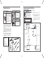
Friedrich WCT08A10A WCT10A10A WCT10A30A WCT12A10A WCT12A30A WCT16A30A WET10A33A WET12A33A WET16A33A WHT12A33A Mode d'emploi
- Catégorie
- Climatiseurs split-system
- Taper
- Mode d'emploi

Installation and Operation Manual
Thru-the-Wall Conditioners
Air Conditioners and Heat Pumps
WallMaster
®
WCT08, WCT10, WCT12
WCT10, WCT12, WCT16, WET10, WET12,
WET16, WHT12
115-Volt:
230-Volt:
93001017_00

2 3
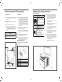
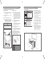
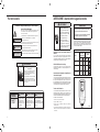
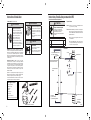
Register your air conditioner
Model information can be found on the name plate
behind the front cover.
Please complete and mail the owner registration
card furnished with this product, or register online
at www.friedrich.com.
For your future convenience, record the model
information here.
MODEL NUMBER
SERIAL NUMBER
PURCHASE DATE
MODEL NUMBER
YS10M10A
SERIAL NUMBER
LICY00008
VOLTS 115
60 HZ / 1 PH
VOLTS MIN 108
COOLING
BTH/HR 6500
EER 12.0
AMPS 8.0
HEATING
BTH/HR 6500
EER 10.4
AMPS 7.0
REFRIGERANT
30.1 OZ R410A
XXXXXXXXX
600 PSIG HS
300 PSIG LS
XXXXXXXXXX
XXXXXXXXX
XXXXXXXXXX
XXXXXXXXXX
FUSE PROTECTED
CIRCUITS USE 15A
TIME DELAY FUSE
X XX
XXXXX
XXXXXXXXXX
U
L
AIR CONDITIONING CO.
SAN ANTONIO, TEXAS
ASSEMBLED IN MEXICO
MODEL NUMBER
YS10M10A
SERIAL NUMBER
LICY00008
AIR CONDITIONING CO.
SAN ANTONIO, TEXAS
ASSEMBLED IN MEXICO
Thank you for your decision to purchase the Friedrich High Efciency Air Conditioner. Your new Friedrich has been carefully engineered and manufactured to
give you many years of dependable, efcient operation, maintaining a comfortable temperature and humidity level. Many extra features have been built into
your unit to assure quiet operation, the greatest circulation of cool, dry air, and the most economic operation.
THANK YOU, on behalf of our entire company,
for making such a wise purchase.
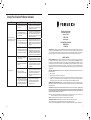
Table of Contents
Safety Precautions ...................................................................................... 4
WARNING: Before Operating Your Unit ..................................................................... 5
Standard Filter Cleaning / Installation Instructions ........................................................... 6
Control Panel Operation .................................................................................. 7
New WallMaster Control Options .......................................................................... 20
Wi-Fi Set-Up Instructions ................................................................................ 21
Control Panel Operation Instructions ....................................................................... 22
Remote Control Operation ................................................................................ 23
Remote Effectiveness .................................................................................... 23
Airow Selection and Adjustment .......................................................................... 23
Installation Instructions .................................................................................. 24
Installation Instructions for WSE Sleeve .................................................................... 25
WallMaster Chassis Installation Instructions ................................................................ 27
Troubleshooting Tips .................................................................................... 29
Warranty .............................................................................................. 31

4 5
Safety Precautions
Your safety and the safety of others is very
important.
We have provided many important safety messages in this manual and on your
appliance. Always read and obey all safety messages.
This is a safety Alert symbol.
This symbol alerts you to potential hazards that can kill or hurt you and others.
All safety messages will follow the safety alert symbol with the word “WARNING”
or “CAUTION”. These words mean:
Indicates a hazard which, if not avoided, can result in severe personal injury or
death and damage to product or other property.
Indicates a hazard which, if not avoided, can result in personal injury and damage to
product or other property.
All safety messages will tell you what the potential hazard is, tell you how to
reduce the chance of injury, and tell you what will happen if the instructions are
not followed.
Indicates property damage can occur if instructions are not followed.
WARNING
Refrigeration system
under high pressure
Do not puncture, heat, expose to ame or incinerate.
Only certied refrigeration technicians should service
this equipment.
R410A systems operate at higher pressures than R22
equipment. Appropriate safe service and handling
practices must be used.
Only use gauge sets designed for use with R410A.
Do not use standard R22 gauge sets.
NOTICE
CAUTION
WARNING
SAFETY
FIRST
WARNING AVERTISSEMENT ADVERTENCIA
Do not remove, disable or
bypass this unit’s safety
devices. Doing so may cause
re, Doing so may cause re,
injuries, or death.
Ne pas supprime, désactiver ou
contourner cette l´unité des
dispositifs de sécurité, faire vous
risqueriez de provoquer le feu, les
blessures ou la mort.
No eliminar, desactivar o pasar
por alto los dispositivos de
seguridad de la unidad. Si lo hace
podría producirse fuego, lesiones
o muerte.
THINK
WARNING
Electrical Shock Hazard
Make sure your electrical receptacle has the
same conguration as your air conditioner’s
plug. If different, consult a Licensed Electrician.
Do not use plug adapters.
Do not use an extension cord.
Do not remove ground prong.
Always plug into a grounded 3 prong outlet.
Failure to follow these instructions can result
in death, re, or electrical shock.
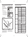
Make sure the wiring is adequate for your unit.
If you have fuses, they should be of the time delay type. Before you install
or relocate this unit, be sure that the amperage rating of the circuit breaker
or time delay fuse does not exceed the amp rating listed in Table 1.
DO NOT use an extension cord.
The cord provided will carry the proper amount of electrical power to the
unit; an extension cord may not.
Make sure that the receptacle is compatible with the air
conditioner cord plug provided.
Proper grounding must be maintained at all times. Two prong receptacles
must be replaced with a grounded receptacle by a certied electrician.
The grounded receptacle should meet all national and local codes and
ordinances. You must use the three prong plug furnished with the air
conditioner. Under no circumstances should you remove the ground
prong from the plug.
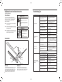
Test the power cord.
All Friedrich room air conditioners are shipped from the factory with a
Leakage Current Detection Interrupter (LCDI) equipped power cord. The
LCDI device on the end of the cord meets the UL and NEC requirements
for cord connected air conditioners.
To test your power supply cord:
1. Plug power supply cord into a grounded 3 prong outlet.
2. Press RESET (see Figure 1).
3. Press TEST, listen for click; the RESET button trips and pops out.
4. Press and release RESET (Listen for click; RESET button latches and
remains in). The power cord is ready for use.
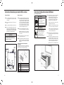
WARNING: Before Operating Your Unit
Figure 1
FRR072
WARNING:
TEST BEFORE EACH USE!
1. PRESS REST BUTTON.
2. PLUG LCDI INTO POWER
RECEPTACLE.
3. PRESS TEST BUTTON,
RESET BUTTON SHOULD
POP UP.
4. PRESS RESET BUTTON
FOR USE.
DO NOT USE IF ABOVE
TEST FAILS.
WHEN GREEN LIGHT
IS ON, IT IS WORKING
PROPERLY!
TEST
RESET
Once plugged in, the unit will operate normally without the need to reset
the LCDI device. If the LCDI device fails to trip when tested or if the
power supply cord is damaged, it must be replaced with a new power
supply cord from the manufacturer. Contact our Technical Assistance
Line at (800) 541-6645. To expedite service, please have your model
number available.
NOTICE
Do not use the LCDI device as an ON/OFF switch.
Failure to adhere to this precaution may cause
premature equipment malfunction.
Table 1
MODEL
CIRCUIT RATING
OR TIME DELAY
FUSE
REQUIRED
WALL
RECEPTACLE
AMP VOLT
NEMA
NO.
WCT08, WCT10,
WCT12 15 125 5-15P
WCT10, WCT12,
WCT16 15 250 6-15P
WET10, WET12,
WET16, WHT12 20 250 6-20P

6 7
Standard Filter Cleaning / Installation Instructions
Figure 2
FRR071
HOW TO CLEAN YOUR AIR FILTER
Your Friedrich room air conditioner is equipped with a permanent/ washable mesh air lter. The lter serves to remove dust, pollen, and other impurities
from the air.
CHECK FILTER LIGHT
Your Friedrich room air conditioner is equipped with a check lter light that will illuminate after *45 – 60 days of fan operation.
To reset the CHECK FILTER reminder press the CHECK FILTER button. (While the reminder is set for 45 – 60 days of operation, we recommend checking
the lter every 30 days for optimal performance.)
*Actual timer is set for 1000 hours of fan cycle operation.
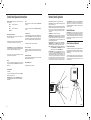
FILTER ACCESS
Remove the FRONT PANEL. Using the handles, pull panel out until it is released from the two retaining snaps. Place the cover aside carefully. Remove the
lter by pulling it from the handles releasing it from the slots on the frame. Wash the lter with water to remove all dust and then rinse, remove water excess
and let it dry – do not twist – then replace the lter by inserting each tab in their respective slot.
Replace the FRONT PANEL by positioning one of the sides in the snaps of the handle rst and then the other side, make sure that both snaps are correctly
aligned and the logo is in the right position.
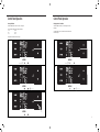
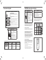
Control Panel Operation
Figure 3
SYSTEM
Cycles between
AUTO, HEAT,
COOL, or FAN
ONLY
(if equipped)
FAN MODE
Sets fan to either:
- Cycle automatically
- Run continuously
FAN SPEED
Sets fan speed:
LOW, MED,
HIGH or AUTO
(if equipped)
TEMPERATURE
Increment UP
TEMPERATURE
Increment DOWN
TIMER
Turns ON or OFF
IR WINDOW
Do not block
ON / OFF
Turns unit on/ off
MODE
Cycles between
COOL, HEAT, FAN
ONLY or -AUTO-
(if equipped)
ON / OFF
Turns unit on/off
-AUTO-
Automatically switches
between cool & heat
CONTROL
LOCKED
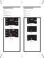
2 DIGIT DISPLAY
Shows Setting for:
- Set Point (Temperature)
- Clock (AM/PM)
WI-FI OPERATING
STATE
TEMPERATURE
UP
TEMPERATURE
DOWN
TIMER
shows on or off
FILTER
Check / clean
FAN SPEED
Sets fan speed:
LOW, MED, HIGH,
OR MAX
(Actual settings are
model dependant)
FAN
Sets fan to either:
- Automatically cycle
- Continuously run
COOL HEAT FAN ONLY DISCONNECTED
FROM POWER BOARD
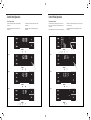
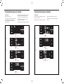
All of the control panel function buttons and mode icons can be viewed in Figure 3.
Power On – Press the button to turn on the air conditioner. The power button illuminates to indicate that the power is on. The backlight on the power switch
will automatically turn off after 20 seconds of inactivity. The remote control can also be used to turn power ON / OFF (See Remote Control).
Display – The display is a high efciency LCD with a built-in backlight. After 20 seconds of inactivity, the display switches off. Touching any button
automatically changes the display to full brightness.
There are three control push buttons on each side of the display.
Figure 4

8 9
Control Panel Operation
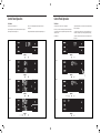
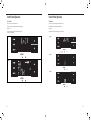
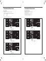
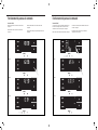
Accessing Sub-Menus
The leftmost MENU button accesses the sub-menu. See Figure 5.
Figure 5
Control Panel Operation
The arrow buttons navigate the 6 menu options (See Figure 6):
– LIM – LOCK
– TM – CnCT
– F-C – diAG
The rightmost button exits the menu. See Figure 7.
MENU
Figure 6
MENU
Figure 7
MENU
Navigating Inside the Sub-Menus
The leftmost MENU button moves you forward through the sub-menu.
See Figure 8.
The rightmost button moves you backward once inside the LIM and TM
menus. See Figure 9.
Figure 8
MENU
Figure 9
MENU

10 11
MENU
MENU
MENU
MENU
Control Panel OperationControl Panel Operation
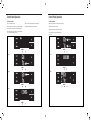
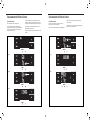
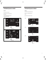
The LIM Menu
This is the limit menu. See Figure 10.
Upon entering the menu, the rst option will be to set the lower setpoint
limit using the arrow buttons. See Figure 11.
Figure 10
MENU
Figure 11
MENU
Figure 12
Figure 13
Then you can set the higher setpoint limit using the arrow buttons.
See Figure 12.
Pressing the leftmost button completes the limit setting. See Figure 13.
The TM Menu
This is the TM menu used to set a timer. See Figure 14.
In the menu, you set the current time using the arrow buttons. See Figure
15. (Note: These two “set clock” steps will be skipped if the unit is already
connected to Wi-Fi.)
First, set the hour.
Figure 14
MENU
Figure 15
MENU
Figure 16
Figure 17
Using the leftmost button, you switch to the minutes and complete setting
the time. See Figure 16.
You select your mode. Either cool, heat, or auto. Toggle these using the
arrow buttons. See Figure 17. (Note: cooling-only models skip this step.)
The process is the same for all three modes. Auto mode will be shown as
the example.

12 13
MENU
MENU
MENU
Control Panel Operation
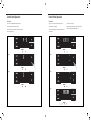
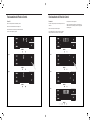
The TM Menu continued
Auto mode selected. See Figure 18.
Set the cool setpoint for your rst timer period using the arrow buttons.
The cooling mode timer only sets the cool setpoint. See Figure 19.
Next, set the heat setpoint for your rst timer period. The heating mode
timer only sets the heat setpoint. See Figure 20.
Figure 18
MENU
Figure 19
MENU
Figure 20
Figure 21
Note: The auto mode timer sets both the cool and heat setpoint.
Set the time to start the rst timer period. See Figure 21.
Control Panel Operation
The TM Menu continued
Set the cool setpoint for the second scheduled timer. See Figure 22.
Set the heat setpoint for the second timer.
Set the time to start the second timer period. See Figure 23.
Press the leftmost button to complete the time timer setup.
See Figure 24.
Figure 22
MENU
Figure 23
Figure 24
MENU

14 15
MENU
Control Panel Operation
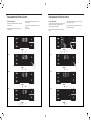
The F-C Menu
This menu is used to toggle between Fahrenheit and Celsius.
This is the Fahrenheit/ Celsius Menu. See Figure 25.
Using the arrow buttons on the right side switches it from Fahrenheit to
Celsius. See Figures 26 and 27.
Figure 25
MENU
Figure 26
MENU
Figure 27
Control Panel Operation
The Lock Menu
This menu is used to lock the changing setting with a password.
This is the Lock Menu. See Figure 28.
The default is the off setting. Use the arrows to toggle between off and
on. See Figure 29.
Figure 28
MENU
Figure 29
MENU
Figure 30
MENU
Figure 31
MENU
This is LOCK on. See Figure 30.
Set the rst digit of the password using the arrow buttons. Use the left-
most button to proceed to the next digit. See Figure 31.

16 17
MENU
Control Panel Operation
The Lock Menu continued
Set the second digit of the password using the same method.
See Figure 32.
Set the third digit of the password using the same method.
See Figure 33.
Figure 32
MENU
Figure 33
MENU
Figure 34
Control Panel Operation
The Lock Menu continued
The ON on the right side of the display shows the lock function is
active. To go back into the menu, select the leftmost button again.
See Figure 36.
Enter the password in the same manner it was created. See Figure 37.
Figure 36
MENU
Figure 37
MENU
Figure 38
MENU
Figure 39
MENU
Entering the correct password will give the user access to all of the sub-
menus. See Figure 38.
Accessing the lock menu will allow you to toggle lock OFF if needed.
See Figure 39.
MENU
Figure 35
Set the fourth digit of the password using the same method.
See Figures 34.
Press the leftmost button to complete the password process.
See Figure 35.

18 19
MENU
Control Panel Operation
The CnCT Menu
This menu is used to turn on Wi-Fi connection.
This is the CnCT menu. Pressing the leftmost button will activate Wi-Fi.
See Figure 40.
The Wi-Fi symbol in the top right corner of the display shows Wi-Fi
connection is on. See Figure 41.
Control Panel Operation
The diAG Menu
This menu is used to access the diagnostic codes. See Figure 42.
Selecting this sub-menu shows the E that represents “Error.”
See Figure 43.
Toggle through the error codes using the arrow keys. See Figure 44.
Figure 42
MENU
Figure 43
MENU
Figure 44
Figure 40
MENU
Figure 41
MENU

20 21
New WallMaster
®
Control Options Wi-Fi Set-Up Instructions
Below are the set-up instructions for Wi-Fi to use your unit wirelessly.
Follow the instructions below:
STEP 1. Using a mobile device such as a smartphone or laptop, navigate
to www.FriedrichConnect.com.
STEP 2. Sign-in using your username and password.
STEP 3. Click the “Add Device” button.
STEP 4. Select the time zone the device is located in and click the “Next”
button.
STEP 5. To start the setup process click the menu button on the home
screen of your WallMaster model.
STEP 6. Using the up and down arrows, navigate to the CnCT screen
(Figure 45).
STEP 7. Click the menu button, this will begin the setup process for your
Friedrich Connect enabled device.
STEP 8. Click the “Next” button on your mobile device.
STEP 9. Follow the on-screen steps to nish adding the device to
your account.
Figure 45
Figure 46
The new WallMaster gives you a variety of options for control, programming,
and scheduling including wireless capabilities.
Wireless Programming and Control:
Friedrich Connect allows you to conveniently control, program, and monitor
your air conditioning unit remotely from a smartphone or computer.
Pre-Programmed Scheduling Options:
Your unit’s digital control comes equipped with a 24-hour timer.
24-Hour Timer
The 24-hour timer allows you to set 2 temperature changes at pre-set times
or a unit control panel.
Customizable Programming Options:
Customizable timers, with up to four temperature adjustments per day, can
be set using Friedrich Connect for one or multiple units.
See www.friedrich.com for complete details on Friedrich Connect.

22 23
30°
45°
60°
30°
45°
60°
25ft
25ft
8ft
4ft
25ft
16ft
6ft
30°
30°
45°
60°
45°
60°
25ft
25ft
25ft
8ft
25ft
25ft
7.5ft
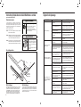
Figure 47
TOP VIEW
SIDE VIEW
FRR080
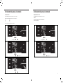
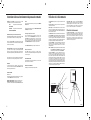
Remote Control Operation
Remote Control - Refer to Figure 47 during operation description.
Getting Started - Install two (2) AAA batteries in the battery compartment
located on the back of the unit.
Operation - The remote control should be within 25 feet of the air conditioner
for operation. (Refer to Figure 47 for effectiveness). Press the power button
to turn the remote on. The remote will automatically power off after 15
seconds if the buttons are not being pressed. The remote must be on to
control the unit.
POWER Button - Turns remote and unit on and off.
SYSTEM Button - Allows the user to sequentially select the following:
AUTO, COOL, HEAT, and FAN ONLY operations. When the button is
pressed, the display indicates which mode has been selected via a display
message. Note that when the heating function is not available, the system
will automatically skip the HEAT mode.
FAN MODE Button - Selects between automatic (AUTO FAN) or
CONTINUOUS operation. In the AUTO FAN mode, the fan only turns on
and off when the compressor operates or the heat function is enabled.
NOTE: AUTO FAN is not available in the FAN ONLY Mode, the display
indicates CONTINUOUS. In the CONTINUOUS mode, fan speed
is determined by your selection on the FAN SPEED button.
FAN SPEED Button - Used to sequentially select new fan speed,
plus AUTO operation. When the FAN SPEED button is pressed, the
fan speed icon (triangle) changes to indicate the new speed level. Fan
speed automatically varies depending on the set temperature on the
control panel and the actual room temperature. For example, if there
is a big difference between your set temperature and the actual room
temperature, the system fan speed increases to HIGH. It remains at
this speed until the room temperature matches the set temperature.
UP and DOWN Arrows - Pressing either the UP or DOWN button
changes the desired room temperature. The factory preset lower and
upper limits are 60 °F (16 °C) and 99 °F (37 °C). These buttons are also
used to navigate between function options when using the User Menu
or Maintenance Mode.
Remote Effectiveness
Handheld Remote - Has an operating range of up to 25 ft. The infrared
remote control signal must have a clear path to transmit the command to
the air conditioning unit. The remote signal has some ability to “bounce”
off of walls and furniture similar to a television remote control. The diagram
below shows the typical operating range of the control in a standard room
with 8 ft high ceilings.
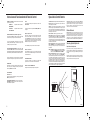
Airflow Selection and Adjustment
Airflow direction adjustment
The airow path may be adjusted to distribute air independently from the
left or right side of the discharge opening. Each of the banks of louvers can
be directed left, right, up, or down in order to achieve the most optimum
airow positioning.
To adjust airow direction, grab the lever in the center of the louver bank
and move it in the direction that you would like the air to be directed. Please
note that it is normal that airow may be stronger out of one side of the
louvers than the other.
Control Panel Operation Instructions
SYSTEM - The MODE button allows you to sequentially select up to four
modes of operation:
AUTO Available on select models
COOL
HEAT Available on select models
FAN ONLY
AUTO FAN (No Cooling Demand)
When in AUTO mode, the fan only operates when the system has a
demand to cool or heat the room.
In the ON fan mode, the fan operates all the time. The system periodically
cools or heats the fan’s airow but the ow of air does not stop.
UP and DOWN Arrows - Pressing either an UP or DOWN button changes
the system’s setpoint (desired room temperature). These buttons are also
used to make system parameter changes later in this manual.
One press equals 1 degree of change in Fahrenheit mode. One press
equals 0.5 degree change in Celsius mode.
TIMER
The timer can be engaged or disengaged from the control panel. This is
done by pressing or holding the UP and DOWN arrows simultaneously for
three seconds.
OTHER FUNCTIONS
°F – °C Select
To switch from degrees Fahrenheit (F) to Celsius (C), press the MENU
button and enter the F-C sub-menu.
FAN SPEED - Depending on your model, the FAN SPEED button allows
you to toggle between three or four modes of operation: LOW, MEDIUM,
HIGH and MAX.
Alerts
When the lter needs to be cleaned or replaced, the CHECK FILTER
icon displays.
The alert can be dismissed by pressing the FAN MODE and TIME for
3 seconds.
Lock Control Panel
To lock/ unlock the front panel controls, navigate to the “LOCK” sub-menu
found after clicking the MENU button. The lock requires a four digit pass code
to lock/ unlock the unit. This pass code will be required to enter the menu to
unlock the unit. The LOCK icon illuminates to indicate the locked status.
The LOCK icon disappears to indicate unlocked status.
External Control Status
The Wi-Fi icon illuminates to indicate that the system is receiving a Wi-
Fi connection. The Wi-Fi icon also provides information about the signal
strength.
ADVANCED FUNCTIONS
The functions mentioned in the following section may or may not be available
depending on the air conditioner model.
Modify the TIMER Function
Navigate to the TIME menu to set the timer.

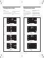
24 25
Figure 48
FRR011
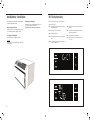
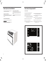
Installation Instructions for WSE Sleeve
(WSE Sleeve Accessory Sold Separately)
Wall Preparation
STEP 1. The wall opening required for a WSE SLEEVE is 17 ¼″ high by
27 ¼″ wide.
STEP 2. LINTELS must be used in opening of brick veneer and masonry
walls to support the material above the WSE SLEEVE. The
following considerations should also be given:
A. Masonry walls to support the material above the WSE SLEEVE.
B. Adjustable SUBBASE (SB) or other unit support must be
provided for panel wall type construction and for walls less
than 8″ thick.
WARNING
Falling Object Hazard
Not following Installation Instructions
for mounting your air conditioner can
result in property damage, injury, or
death.
Mounting Hardware
ITEM
NO
DESCRIPTION QTY.
1 SCREW, #12A x 2″ 7
24″ MINIMUM REQUIRED FROM
TOP OF UNIT TO CEILING
INSIDE
WALL
LINTELS
1″ MINIMUM SPACING REQUIRED
ON ALL SIDES OF UNIT
7
/8″ MINIMUM BEYOND
INSIDE WALL
1″ MINIMUM
3
1
/2″ FOR SUBBASE
5
1
/2″ MAXIMUM FOR SUBBASE
OUTSIDE WALL
WSE SLEEVE
WALL MOUNT
SCREW LOCATIONS
DRAIN EXTENSION
5″ (127 mm)
5″ (127 mm)
9
/16″ MINIMUM BEYOND
OUTSIDE WALL
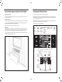
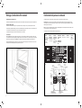
IMPORTANT: Before you begin the actual installation of your air
conditioner, check your local electrical codes and the information below.
Your air conditioner must be connected to a power source with the same
alternating current (A.C.) voltage and amperage as marked on the name
plate located on the chassis. Only A.C. can be used. Direct Current (D.C.)
cannot be used.
CIRCUIT PROTECTION – Use on single outlet circuit only. An overloaded
circuit will invariably cause malfunction or failure of an air conditioner;
therefore, it is necessary that the electrical protection is adequate. Due
to momentary high current demand when the air conditioner starts, use a
“TIME DELAY” fuse or a HACR type circuit breaker. Consult your dealer or
power company if in doubt.
Refer to the electrical name plate located on the air conditioner chassis
(see Page 2) to determine the correct fuse or circuit breaker amperage for
your model (see Table 1 on Page 5 for electrical receptacle types).
The power cord has a plug with a grounding prong and a matching
receptacle is required.
Installation Instructions
READ THIS FIRST! Electrical Requirements
WARNING
Electrical Shock Hazard
Make sure your electrical receptacle has the
same conguration as your air conditioner’s
plug. If different, consult a Licensed Electrician.
Do not use plug adapters.
Do not use an extension cord.
Do not remove ground prong.
Always plug into a grounded 3 prong outlet.
Failure to follow these instructions can result
in death, re, or electrical shock.
WARNING
MOVING PARTS HAZARDS
• Do not operate unit out of sleeve or
with front grille removed.
• Do not place hands in blower or fan
blade areas.
Failure to do so can result in serious injury.
CAUTION
Excessive Weight Hazard
Use two or more people when installing your
air conditioner.
Failure to do so can result in back or other
injury.
Recommended Tools
1. Power Drill
2.
5
/32" Drill Bit
3. Gloves
4. Carpenters Level
5.
5
/16" Wrench
6.
1
/4" Wrench
7. #2 Phillips Screw Driver
8. Putty Knife or (wood stir stick)
1
2
3
4
65
87
5/16
5/16
1/4
1/4
ITEMS NOT TO SCALE
SIDE VIEW

26 27
CAUTION
Excessive Weight Hazard
Use two or more people when installing your
air conditioner.
Failure to do so can result in back or other
injury.
STEP 1. Check the sleeve to be certain it has been correctly installed
in the wall. Remove the front panel on the WSE SLEEVE.
Remove the rear WEATHER PANEL. Reverse grille. Place
lower edge into sleeve tab (Friedrich logo facing out). Align
slots with the screw holes. Secure grille with screws.
A. Check the anchor screw. There should be four (4) in the WSE
SLEEVE (two in each side).
B. Determine if the sleeve has a downward slope of
3
/8″ to the
outside. See Page 26 for further details.
C. Check to be sure the sleeve has been sealed around all
edges with an industrial type caulking on both the outside
and inside to prevent rain entry.
STEP 3. Check the electrical receptacle to see that it conforms to the
requirements for the chassis model to be installed. See Page 5
for the receptacle requirements.
STEP 3. Remove the chassis from the shipping carton. Lift the chassis
by the basepan and slide it into the front of the sleeve. (Obtain
assistance as needed.) Push the chassis all the way into the
sleeve, using the plastic front handles, so that the front panel
meets the front edge of the shell.
NOTE: Chassis comes with pre-installed seal gasket.
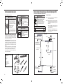
Figure 49
Installation Instructions for WSE Sleeve continued
CAULK
(AS NEEDED)
FRONT
OF UNIT
FRONT
UNIT
REST
LEVEL
BACK
UNIT
REST
SHIM TO
PROPER
SPACING
CAULK
(AS NEEDED)
BACK
OF UNIT
3
/8″
SLOPE
CAULK
(AS NEEDED)
NOTICE
Sleeve projections and leveling precautions must be
observed to prevent the entry of water into the room.
A
WSE SLEEVE
B 61603200 INDOOR WEATHER PANEL (METAL)
C 61603304 OUTDOOR WEATHER PANEL (PAINTED METAL)
D 61603012 ASSY GRILLE WSE SLEEVE
E 61578101 GASKET (ATTACHED TO SLEEVE)
WallMaster Chassis Installation Instructions
for WCT, WET and WHT models
CAUTION
Cut/Sever
Although great care has been
taken to minimize sharp edges
in the construction of your unit,
use gloves or other hand
protection when handling unit
Failure to do so can result in minor
to moderate personal injury.
Figure 51
Installation Requirements
STEP 1. The WSE sleeve should be positioned so that the drain
extension extends a minimum of
9
/16″ beyond the outside wall
(see Figure 48).
STEP 2. The WSE sleeve must extend a minimum of
7
/8″ beyond the
inside wall.
STEP 3. The WSE sleeve must be installed level side to side.
STEP 4. The WSE sleeve must also be installed with a downward tilt
toward the outside of the building. If a level is placed so that
it rests on the front and back unit rest as shown in Figure 49, a
properly installed unit provides a
3
/8″ slope to the outside of the
building.
Sleeve Requirements
STEP 1. After unpacking the WSE sleeve from the carton, remove the
indoor weather panel. Place the WSE sleeve in the wall opening
following the instructions given in the Installation Requirements.
Attach the sleeve to the inside wall by driving two #12A x 2″
screws in each side of the sleeve (see Figure 50). Shim at the
top of the sleeve, midway between the sides. Drive one #12A
x 2″ screw in the top of the sleeve. If the wall opening is not
framed with wood, use expansion anchor bolts or molly (toggle)
bolts (not provided).
STEP 2. Once the sleeve has been installed, check the level again to be
sure the
3
/8″ downward slope is maintained.
NOTE: If necessary, apply shims below the chassis and inside
the sleeve front unit rest, to ensure a
3
/8″ downward slope front
to back.
STEP 3. Caulk the perimeter of the entire opening on the inside and the
outside between the sleeve and the wall.
STEP 4. The indoor weather panel removed in Step 1 above must be
remounted back in place if masonry work is to be done and/ or if
the “WallMaster”chassis is to be installed at a later date.
How to cover inner weather panel holes
Two beige plugs are included in the plastic bag taped to the WallMaster
chassis. These plugs may be used to cover the two holes left after removing
the indoor weather panel.
Figure 50

28 29
COMPLAINT CAUSE SOLUTION
Unit does not operate.
• The unit is turned to the off position, or the
thermostat is satised.
• Turn the unit to the on position and raise or lower
temperature setting (as appropriate) to call for
operation.
• The LCDI power cord is unplugged.
• Plug into a properly grounded 3 prong receptacle.
See “Electrical Rating Tables” on Page 5 for the
proper receptacle type for your unit.
• The LCDI power cord has tripped (Reset
button has popped out).
• Press and release RESET (Listen for click. Reset
button latches and remains in.) to resume operation.
• The circuit breaker has tripped or the
supply circuit fuse has blown.
• Reset the circuit breaker, or replace the fuse as
applicable. If the problem continues, contact a
licensed electrician.
• There has been a local power failure.
• The unit will resume normal operation once power
has been restored.
Unit Trips Circuit Breaker or
Blows Fuses.
• Other appliances are being used on the
same circuit.
• The unit requires a dedicated outlet circuit, not shared
with other appliances.
• An extension cord is being used.
• Do NOT use an extension cord with this or any other
air conditioner.
• The circuit breaker or time-delay fuse is
not of the proper rating.
• Replace with a circuit breaker or time-delay fuse of
the proper rating. See “Electrical Rating Tables” on
Page 5 for the proper circuit breaker/ fuse rating for
your unit. If the problem continues, contact a licensed
electrician.
LCDI Power Cord Trips
(Reset Button Pops Out).
• The LCDI power cord can trip (Reset
button pops out) due to disturbances on
your power supply line.
• Press and release RESET (Listen for click. Reset
button latches and remains in.) to resume normal
operation.
• Electrical overload, overheating, or cord
pinching can trip (Reset button pops out)
the LCDI power cord.
• Once the problem has been determined and
corrected, press and release RESET (Listen for
click. Reset button latches and remains in.) to
resume normal operation.
NOTE: A damaged power supply cord must be replaced with a new power supply cord obtained from the
product manufacturer and must not be repaired.
Unit Does Not Cool/ Heat Room
Sufciently, or Cycles On And Off
Too Frequently.
• The return/ discharge air grille is blocked.
• Ensure that the return and/ or discharge air paths are
not blocked by curtains, blinds, furniture, etc.
• Windows or doors to the outside are open. • Ensure that all windows and doors are closed.
• The temperature is not set at a cool
enough/ warm enough setting.
• Adjust the Temperature control to a cooler or warmer
setting as necessary.
• The lter is dirty or obstructed.
• Clean the lter, (See Routine Maintenance), or
remove obstruction.
• The indoor coil or outdoor coil is dirty or
obstructed.
• Clean the coils, (See Routine Maintenance), or
remove obstruction.
• There is excessive heat or moisture
(cooking, showers, etc.) in the room.
• Be sure to use exhaust vent fans while cooking or
bathing and, if possible, try not to use heat producing
appliances during the hottest part of the day.
• The temperature of the room you are
trying to cool is extremely hot.
• Allow additional time for the air conditioner to cool off
a very hot room.
Troubleshooting Tips
WARNING
MOVING PARTS HAZARDS
• Do not operate unit out of sleeve or
with front grille removed.
• Do not place hands in blower or fan
blade areas.
Failure to do so can result in serious injury.
MOVING OBJECT HAZARD
WARNING
Replace all panels before operating your air
conditioner.
Failure to do so can result in severe personal
injury or death and damage to product or other
property.
WallMaster Chassis Installation Instructions
for WCT, WET and WHT models
Condensate Removal
If you desire to drain condensate from the basepan during unit
operation, this unit is provided with a drain nipple that can be attached
to the basepan. You must provide a
3
/8″ outside diameter thin-wall
plastic or copper tube which will attach to the drain nipple.
Follow the instructions below:
STEP 1. Find the drain rubber plug on the rear of the basepan and
remove it (see Figure 52).
STEP 2. Remove the knockout in the lower right side of the rear grille.
Slide the chassis into the WSE SLEEVE so that the drain nipple
extends through the knockout.
STEP 3. Slide the tubing over the drain nipple. If the chassis must be
removed from the sleeve for service, remove the clamped drain
hose before sliding the chassis out of the sleeve.
IDK (Drain Kit)
New construction allowing for condensate drain systems built
within the walls can use the Friedrich Interior Drain Kit (Accessory
#IDK). This kit is designed for installation in the bottom of the sleeve
below the condensate bellows valve (heat/ cool models only).
Alternate Drain Kits
DK (Drain Kit)
In the event that the outdoor temperature drops below 37 °F, any water
that remains in the chassis basepan is drained into the sleeve pan
on WET and WHT models to prevent freezing. (NOTE: In the cooling
mode of the WCT, WET and WHT models, condensate overow is
possible in very humid climates). For these particular instances, an
optional drain kit (Accessory #DK) is available for water removal.
Figure 52
DRAIN
HOSE
DRAIN
NIPPLE
BASEPAN
SLEEVE

30 31
COMPLAINT CAUSE SOLUTION
Unit Does Not Cool/ Heat Room
Sufciently, or Cycles On And Off
Too Frequently (continued).
• The outside temperature is below 60 °F
(16 °C).
• Do not try to operate your air conditioner in the
cooling mode when the outside temperature is below
60 °F (16 °C). The unit will not cool properly, and the
unit may be damaged.
• The digital control is set to fan cycling mode.
• Since the fan does not circulate the room air
continuously at this setting, the room air does not
mix as well and hot (or cold) spots may result. Using
the continuous fan setting is recommended to obtain
optimum comfort levels.
• The air conditioner has insufcient cooling
capacity to match the heat gain of the room.
• Check the cooling capacity of your unit to ensure it
is properly sized for the room in which it is installed.
Room air conditioners are not designed to cool
multiple rooms.
• The air conditioner has insufcient heating
capacity to match the heat loss of the room.
• Check the heating capacity of your unit. Air conditioners
are sized to meet the cooling load, and heater size
is then selected to meet the heating load. In extreme
northern climates, room air conditioners may not be able
to be used as a primary source of heat.
Unit Runs Too Much.
• This may be due to an excessive heat load
in the room.
• If there are heat producing appliances in use in the
room, or if the room is heavily occupied, the unit will
need to run longer to remove the additional heat.
• It may also be due to an improperly sized unit.
• Be sure to use exhaust vent fans while cooking or
bathing and, if possible, try not to use heat producing
appliances during the hottest part of the day.
• This may be normal for higher efciency
(EER) air conditioners.
• The use of higher efciency components in your new
air conditioner may result in the unit running longer
than you feel it should. This may be more apparent, if
it replaced an older, less efcient, model. The actual
energy usage, however, will be signicantly less
when compared to older models.
• You may notice that the discharge air
temperature of your new air conditioner
may not seem as cold as you may be
accustomed to from older units. This
does not; however, indicate a reduction
in the cooling capacity of the unit.
• The energy efciency ratio (EER) and cooling
capacity rating (Btu/ h) listed on the unit’s rating
plate are both agency certied.
Troubleshooting Tips continued
Friedrich Air Conditioning Company
10001 Reunion Place, Suite 500
San Antonio, TX 78216
1-800-541-6645
www.friedrich.com
WALLMASTER
®
THRU-THE-WALL AIR CONDITIONERS
LIMITED WARRANTY
FIRST YEAR
ANY PART: If any part supplied by FRIEDRICH fails because of a defect in workmanship or material within twelve months from date of original purchase,
FRIEDRICH will repair the product at no charge, provided room air conditioner is reasonably accessible for service. Any additional labor cost for removing
inaccessible units and/or charges for mileage related to travel by a Service Agency that exceeds 25 miles one way will be the responsibility of the owner. This
remedy is expressly agreed to be the exclusive remedy within twelve months from the date of the original purchase.
SECOND THROUGH FIFTH YEAR
SEALED REFRIGERANT SYSTEM: If the Sealed Refrigeration System (dened for this purpose as the compressor, condenser coil, evaporator coil,
reversing valve, check valve, capillary, lter drier, and all interconnecting tubing) supplied by FRIEDRICH in your Room Air Conditioner fails because of
a defect in workmanship or material within sixty months from date of purchase, FRIEDRICH will pay a labor allowance and parts necessary to repair the
Sealed Refrigeration System; PROVIDED FRIEDRICH will not pay the cost of diagnosis of the problem, removal, freight charges, and transportation of the
air conditioner to and from the Service Agency, and the reinstallation charges associated with repair of the Sealed Refrigeration System. All such cost will be
the sole responsibility of the owner. This remedy is expressly agreed to be the exclusive remedy within sixty months from the date of the original purchase.
APPLICABILITY AND LIMITATIONS: This warranty is applicable only to units retained within the Fifty States of the U.S.A., District of Columbia, and Canada.
This warranty is not applicable to:
1. Air lters or fuses.
2. Products on which the model and serial numbers have been removed.
3. Products which have defects or damage which results from improper installation, wiring, electrical current characteristics, or maintenance; or caused by
accident, misuse or abuse, re, ood, alterations and/or misapplication of the product and/or units installed in a corrosive atmosphere, default or delay in
performance caused by war, government restrictions or restraints, strikes, material shortages beyond the control of FRIEDRICH, or acts of God.
OBTAINING WARRANTY PERFORMANCE: Service will be provided by the FRIEDRICH Authorized Dealer or Service Organization in your area. They are listed
in the Yellow Pages. If assistance is required in obtaining warranty performance, write to: Room Air Conditioner Service Manager, Friedrich Air Conditioning Co.
LIMITATIONS: THIS WARRANTY IS GIVEN IN LIEU OF ALL OTHER WARRANTIES. Anything in the warranty notwithstanding, ANY IMPLIED WARRANTIES
OF FITNESS FOR PARTICULAR PURPOSE AND/OR MERCHANTABILITY SHALL BE LIMITED TO THE DURATION OF THIS EXPRESS WARRANTY.
MANUFACTURER EXPRESSLY DISCLAIMS AND EXCLUDES ANY LIABILITY FOR CONSEQUENTIAL OR INCIDENTAL DAMAGE FOR BREACH OF
ANY EXPRESSED OR IMPLIED WARRANTY.
NOTE: Some states do not allow limitations on how long an implied warranty lasts, or do not allow the limitation or exclusion of consequential or incidental
damages, so the foregoing exclusions and limitations may not apply to you.
OTHER: This warranty gives you specic legal rights, and you may also have other rights which vary from state to state.
PROOF OF PURCHASE: Owner must provide proof of purchase in order to receive any warranty related services.
All service calls for explaining the operation of this product will be the sole responsibility of the consumer.
All warranty service must be provided by an Authorized FRIEDRICH Service Agency, unless authorized by FRIEDRICH prior to repairs being made.

Friedrich Air Conditioning Co.
10001 Reunion Place, Suite 500 • San Antonio, Texas 78216
1-800-541-6645
www.friedrich.com
Printed in Mexico
93001017_00

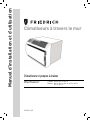
Manual de Instalación y Funcionamiento
Aire Acondicionados de Pared
Aire Acondicionadores y Bombas de Calor
WallMaster
®
WCT08, WCT10, WCT12
WCT10, WCT12, WCT16, WET10, WET12,
WET16, WHT12
115-Volt:
230-Volt:
93001017_00

2 3
Tabla de Contenidos
Precauciones de Seguridad .............................................................................. 4
ADVERTENCIA: Antes de Operar su Unidad .................................................................. 5
Instrucciones de Limpieza / Instalación de Filtros Estándar .................................................... 6
Funcionamiento del Panel de Control . . . . . . . . . . . . . . . . . . . . . . . . . . . . . . . . . . . . . . . . . . . . . . . . . . . . . . . . . . . . . . . . . . . . . . . 7
Nuevas Opciones del Control WallMaster ................................................................... 20
Instrucciones de Conguración de Wi-Fi .................................................................... 21
Instrucciones de Funcionamiento del Panel de Control ........................................................ 22
Funcionamiento del Control Remoto ....................................................................... 23
Ecacia a Distancia ...................................................................................... 23
Selección y Ajuste del Flujo de Aire ......................................................................... 23
Instrucciones de Instalación .............................................................................. 24
Instrucciones de Instalación para WSE Manga ............................................................... 25
Instrucciones de Instalación del Chasis WallMaster ........................................................... 27
Consejos Para Solucionar Problemas ...................................................................... 29
Garantía ............................................................................................... 31
Registre su aíre acondicionado
La información del modelo se puede encontrar en
la placa de identicación detrás de la tapa frontal.
Por favor, complete y envíe por correo la tarjeta
de registro del propietario proporcionada con este
producto o regístrese en línea en www.friedrich.com.
Para su futura comodidad, registre la información
del modelo aquí.
NÚMERO DE MODELO
NÚMERO DE SERIE
FECHA DE COMPRA
MODEL NUMBER
YS10M10A
SERIAL NUMBER
LICY00008
VOLTS 115
60 HZ / 1 PH
VOLTS MIN 108
COOLING
BTH/HR 6500
EER 12.0
AMPS 8.0
HEATING
BTH/HR 6500
EER 10.4
AMPS 7.0
REFRIGERANT
30.1 OZ R410A
XXXXXXXXX
600 PSIG HS
300 PSIG LS
XXXXXXXXXX
XXXXXXXXX
XXXXXXXXXX
XXXXXXXXXX
FUSE PROTECTED
CIRCUITS USE 15A
TIME DELAY FUSE
X XX
XXXXX
XXXXXXXXXX
U
L
AIR CONDITIONING CO.
SAN ANTONIO, TEXAS
ASSEMBLED IN MEXICO
MODEL NUMBER
YS10M10A
SERIAL NUMBER
LICY00008
AIR CONDITIONING CO.
SAN ANTONIO, TEXAS
ASSEMBLED IN MEXICO
GRACIAS, en nombre de toda nuestra empresa, por hacer
una compra tan sabia.
Gracias por su decisión de comprar el Aire Acondicionado Friedrich de Alta Eciencia. Su nuevo Friedrich ha sido cuidadosamente diseñado y fabricado para
darle muchos años de funcionamiento conable y eciente, manteniendo una temperatura confortable y nivel de humedad. Muchas características adicionales
han sido incorporadas en su unidad para asegurar un funcionamiento silencioso, la mayor circulación de aire fresco y seco, y la operación más económica.

4 5
Figura 1
FRR072
WARNING:
TEST BEFORE EACH USE!
1. PRESS REST BUTTON.
2. PLUG LCDI INTO POWER
RECEPTACLE.
3. PRESS TEST BUTTON,
RESET BUTTON SHOULD
POP UP.
4. PRESS RESET BUTTON
FOR USE.
DO NOT USE IF ABOVE
TEST FAILS.
WHEN GREEN LIGHT
IS ON, IT IS WORKING
PROPERLY!
TEST
RESET
Tabla 1
MODELO
POTENCIA DEL
CIRCUITO O FUSIBLE
DE RETARDO POR
RECEPTÁCULO DE
PARED
REQUERIDO
AMP VOLT
NEMA
NO.
WCT08, WCT10,
WCT12 15 125 5-15P
WCT10, WCT12,
WCT16 15 250 6-15P
WET10, WET12,
WET16, WHT12 20 250 6-20P
Su seguridad y la seguridad de los demás son
muy importantes.
Hemos proporcionado muchos mensajes de seguridad importantes en este
manual y en su electrodoméstico. Siempre lea y obedezca todos los mensajes de
seguridad.
Este es un símbolo de alerta de seguridad.
Este símbolo le advierte de los peligros potenciales que pueden matar o lastimar a
usted y a los demás.
Todos los mensajes de seguridad le seguirán al símbolo de alerta de seguridad con
la palabra “ADVERTENCIA” o “PRECAUCIÓN”. Estas palabras signican:
Indica un peligro que, de no evitarse, puede resultar en lesiones personales graves
o en la muerte y en daños al producto u otros bienes.
Indica un peligro que, de no evitarse, puede resultar en lesiones personales y en
daños al producto u otros bienes.
Todos los mensajes de seguridad le dirán cuál es el peligro potencial, le dirán
cómo reducir el riesgo de lesiones, y le dirán lo que sucederá si no se siguen las
instrucciones.
Indica que le pueden ocurrir daños a los bienes si no se siguen las instrucciones.
AVISO
PRECAUCIÓN
ADVERTENCIA
ADVERTENCIA
Peligro de choque eléctrico
Asegúrese de que su enchufe tenga la misma
conguración eléctrica que el acondicionador
de aire. Si es diferente, consulte a un electricista
autorizado.
No utilice adaptadores de enchufe.
No utilice un cable de extensión.
No quite la clavija de tierra.
Siempre conecte a un enchufe de tres clavijas.
El no cumplir con estas instrucciones se puede
ocasionar la muerte, un incendio o un choque
eléctrico.
Asegúrese de que el cableado sea adecuado para su unidad.
Si tiene fusibles, deben ser del tipo de retardo. Antes de instalar o
trasladar esta unidad, asegúrese de que el amperaje del interruptor o
el fusible de retardo no superen el amperaje en el Cuadro 1.
NO utilice un cable de extensión.
El cable proporcionado le suministrará la cantidad de energía
eléctrica adecuada a la unidad; puede que un cable de extensión no.
Asegúrese de que la toma de corriente sea compatible con el
enchufe del aire acondicionado proporcionado.
Esto garantiza una conexión a tierra adecuada. Si usted tiene una toma
de corriente de dos clavijas, tendrá que solicitar que un electricista
certicado se lo sustituya por una toma de corriente conectada a tierra.
La toma de corriente conectada a tierra debe cumplir con todos los
códigos y reglamentos locales y nacionales. Bajo ninguna circunstancia
se deberá quitar la clavija de tierra del enchufe. Debe utilizar el enchufe
de tres clavijas suministrado con el aire acondicionado.
Prueba el cable de alimentación.
Todos los acondicionadores de aire habitación de Friedrich se envían
desde la fábrica con un cable de alimentación equipado con un Interruptor
de detección de fugas (LCDI). El aparato de LCDI en la punta del cable
cumple con los requisitos de UL y NEC para los aires acondicionados con
la conexión de cable.
Para probar el cable de alimentación:
1. Enchufe el cable de alimentación a un enchufe de tierra de tres clavijas.
2. Presione RESET (vea gura 1).
3. Presione TEST, escuche el clic; el botón de RESET se sale.
4. Presione y suelte RESET (Escuche clic; el botón de RESET se mantiene
para adentro). El cable de alimentación está listo para su uso.
ADVERTENCIA: Antes de Operar Su Unidad
La unidad funcionará normalmente ya que esté conectado, sin
necesidad de reiniciar el aparato LCDI. Si el aparato de LCDI no
dispara durante la prueba o si el cable de alimentación está dañado, se
debe reemplazar con un nuevo cable de alimentación del fabricante.
Contacta nuestra Asistencia Técnica al (800) 541-6645. Para facilitar
el servicio, por favor tenga su número de serie.
AVISO
No utilice el aparato de LCDI como un interruptor
ON / OFF (encender/apagar).
Se puede causar mal funcionamiento prematuro del
equipo si no sigue esta precaución.
SEGURIDAD
PRIMERO
WARNING AVERTISSEMENT ADVERTENCIA
Do not remove, disable or
bypass this unit’s safety
devices. Doing so may cause
re, Doing so may cause re,
injuries, or death.
Ne pas supprime, désactiver ou
contourner cette l´unité des
dispositifs de sécurité, faire vous
risqueriez de provoquer le feu, les
blessures ou la mort.
No eliminar, desactivar o pasar
por alto los dispositivos de
seguridad de la unidad. Si lo hace
podría producirse fuego, lesiones
o muerte.
PENSAR
ADVERTENCIA
Sistema de refrigeración
a alta presión
No perforar, calentar, exponer a las llamas o incinerar.
Únicamente los técnicos certicados en refrigeración
deben reparar este equipo.
Los sistemas R410A funcionan a presiones más
altas que el equipo R22. Se deben utilizar prácticas
adecuadas de servicio y manejo seguro.
Únicamente utilice los medidores de presión diseñados
para su uso con R410A. No utilice los medidores de
presión estándar R22.
Precauciones de Seguridad
La page charge ...
La page charge ...
La page charge ...
La page charge ...
La page charge ...
La page charge ...
La page charge ...
La page charge ...
La page charge ...
La page charge ...
La page charge ...
La page charge ...
La page charge ...
La page charge ...
La page charge ...
La page charge ...
La page charge ...
La page charge ...
La page charge ...
La page charge ...
La page charge ...
La page charge ...
La page charge ...
La page charge ...
La page charge ...
La page charge ...
La page charge ...
La page charge ...
La page charge ...
La page charge ...
La page charge ...
-
 1
1
-
 2
2
-
 3
3
-
 4
4
-
 5
5
-
 6
6
-
 7
7
-
 8
8
-
 9
9
-
 10
10
-
 11
11
-
 12
12
-
 13
13
-
 14
14
-
 15
15
-
 16
16
-
 17
17
-
 18
18
-
 19
19
-
 20
20
-
 21
21
-
 22
22
-
 23
23
-
 24
24
-
 25
25
-
 26
26
-
 27
27
-
 28
28
-
 29
29
-
 30
30
-
 31
31
-
 32
32
-
 33
33
-
 34
34
-
 35
35
-
 36
36
-
 37
37
-
 38
38
-
 39
39
-
 40
40
-
 41
41
-
 42
42
-
 43
43
-
 44
44
-
 45
45
-
 46
46
-
 47
47
-
 48
48
-
 49
49
-
 50
50
-
 51
51


Friedrich WCT08A10A WCT10A10A WCT10A30A WCT12A10A WCT12A30A WCT16A30A WET10A33A WET12A33A WET16A33A WHT12A33A Mode d'emploi
- Catégorie
- Climatiseurs split-system
- Taper
- Mode d'emploi
dans d''autres langues
Documents connexes
-
Friedrich KCQ05A10A Guide d'installation
-
Friedrich KCS10A10A Guide d'installation
-
Friedrich WET16A33A Guide d'installation
-
Friedrich WS08D10A WallMaster Installation and Operation Manual
-
-
-
-
Friedrich UCT10A10A Mode d'emploi
-