Extron XTP T USW 103 4K Manuel utilisateur
- Catégorie
- Commutateurs vidéo
- Taper
- Manuel utilisateur

User Guide
XTP T USW 103 4K
XTP Systems
Three Input Switcher
with an Integrated XTP Transmitter
68-3217-01 Rev. A
05 19

Safety Instructions
Safety Instructions • English
WARNING: This symbol, , when used on the product, is intended to
alert the user of the presence of uninsulated dangerous voltage within the
product’s enclosure that may present a risk of electric shock.
ATTENTION: This symbol, , when used on the product, is intended
to alert the user of important operating and maintenance (servicing)
instructions in the literature provided with the equipment.
For information on safety guidelines, regulatory compliances, EMI/EMF
compatibility, accessibility, and related topics, see the Extron Safety and
Regulatory Compliance Guide, part number 68-290-01, on the Extron
website, www.extron.com.
Sicherheitsanweisungen • Deutsch
WARNUNG: Dieses Symbol auf dem Produkt soll den Benutzer darauf
aufmerksam machen, dass im Inneren des Gehäuses dieses Produktes
gefährliche Spannungen herrschen, die nicht isoliert sind und die einen
elektrischen Schlag verursachen können.
VORSICHT: Dieses Symbol auf dem Produkt soll dem Benutzer in
der im Lieferumfang enthaltenen Dokumentation besonders wichtige
Hinweise zur Bedienung und Wartung (Instandhaltung) geben.
Weitere Informationen über die Sicherheitsrichtlinien, Produkthandhabung,
EMI/EMF-Kompatibilität, Zugänglichkeit und verwandte Themen finden Sie in
den Extron-Richtlinien für Sicherheit und Handhabung (Artikelnummer
68-290-01) auf der Extron-Website, www.extron.com.
Instrucciones de seguridad • Español
ADVERTENCIA: Este símbolo, , cuando se utiliza en el producto,
avisa al usuario de la presencia de voltaje peligroso sin aislar dentro del
producto, lo que puede representar un riesgo de descarga eléctrica.
ATENCIÓN: Este símbolo, , cuando se utiliza en el producto, avisa
al usuario de la presencia de importantes instrucciones de uso y
mantenimiento recogidas en la documentación proporcionada con el
equipo.
Para obtener información sobre directrices de seguridad, cumplimiento
de normativas, compatibilidad electromagnética, accesibilidad y temas
relacionados, consulte la Guía de cumplimiento de normativas y seguridad
de Extron, referencia 68-290-01, en el sitio Web de Extron, www.extron.com.
Instructions de sécurité • Français
AVERTISSEMENT : Ce pictogramme, , lorsqu’il est utilisé sur le
produit, signale à l’utilisateur la présence à l’intérieur du boîtier du
produit d’une tension électrique dangereuse susceptible de provoquer
un choc électrique.
ATTENTION : Ce pictogramme, , lorsqu’il est utilisé sur le produit,
signale à l’utilisateur des instructions d’utilisation ou de maintenance
importantes qui se trouvent dans la documentation fournie avec le
matériel.
Pour en savoir plus sur les règles de sécurité, la conformité à la
réglementation, la compatibilité EMI/EMF, l’accessibilité, et autres sujets
connexes, lisez les informations de sécurité et de conformité Extron, réf.
68-290-01, sur le site Extron, www.extron.com.
Istruzioni di sicurezza • Italiano
AVVERTENZA: Il simbolo, , se usato sul prodotto, serve ad
avvertire l’utente della presenza di tensione non isolata pericolosa
all’interno del contenitore del prodotto che può costituire un rischio di
scosse elettriche.
ATTENTZIONE: Il simbolo, , se usato sul prodotto, serve ad avvertire
l’utente della presenza di importanti istruzioni di funzionamento e
manutenzione nella documentazione fornita con l’apparecchio.
Per informazioni su parametri di sicurezza, conformità alle normative,
compatibilità EMI/EMF, accessibilità e argomenti simili, fare riferimento
alla Guida alla conformità normativa e di sicurezza di Extron, cod. articolo
68-290-01, sul sito web di Extron, www.extron.com.
Instrukcje bezpieczeństwa • Polska
OSTRZEŻENIE: Ten symbol, , gdy używany na produkt, ma na celu
poinformować użytkownika o obecności izolowanego i niebezpiecznego
napięcia wewnątrz obudowy produktu, który może stanowić zagrożenie
porażenia prądem elektrycznym.
UWAGI: Ten symbol, , gdy używany na produkt, jest przeznaczony do
ostrzegania użytkownika ważne operacyjne oraz instrukcje konserwacji
(obsługi) w literaturze, wyposażone w sprzęt.
Informacji na temat wytycznych w sprawie bezpieczeństwa, regulacji
wzajemnej zgodności, zgodność EMI/EMF, dostępności i Tematy pokrewne,
zobacz Extron bezpieczeństwa i regulacyjnego zgodności przewodnik, część
numer 68-290-01, na stronie internetowej Extron, www.extron.com.
Инструкция по технике безопасности • Русский
ПРЕДУПРЕЖДЕНИЕ: Данный символ, , если указан
на продукте, предупреждает пользователя о наличии
неизолированного опасного напряжения внутри корпуса
продукта, которое может привести к поражению электрическим
током.
ВНИМАНИЕ: Данный символ, , если указан на продукте,
предупреждает пользователя о наличии важных инструкций
по эксплуатации и обслуживанию в руководстве,
прилагаемом к данному оборудованию.
Для получения информации о правилах техники безопасности,
соблюдении нормативных требований, электромагнитной
совместимости (ЭМП/ЭДС), возможности доступа и других
вопросах см. руководство по безопасности и соблюдению
нормативных требований Extron на сайте Extron: ,
www.extron.com, номер по каталогу - 68-290-01.
安全说明 • 简体中文
警告: 产品上的这个标志意在警告用户该产品机壳内有暴露的危险 电压,
有触电危险。
注意: 产品上的这个标志意在提示用户设备随附的用户手册中有
重要的操作和维护(维修)说明。
关于我们产品的安全指南、遵循的规范、EMI/EMF 的兼容性、无障碍
使用的特性等相关内容,敬请访问 Extron 网站 , www.extron.com,参见
Extron 安全规范指南,产品编号 68-290-01。

Copyright
© 2019 Extron Electronics. All rights reserved. www.extron.com
Trademarks
All trademarks mentioned in this guide are the properties of their respective owners.
The following registered trademarks (
®
), registered service marks (
SM
), and trademarks (
TM
) are the property of RGBSystems, Inc. or
ExtronElectronics (see the current list of trademarks on the Terms of Use page at www.extron.com):
Registered Trademarks
(
®
)
Extron, Cable Cubby, ControlScript, CrossPoint, DTP, eBUS, EDID Manager, EDID Minder, Flat Field, FlexOS, Glitch Free. Global
Configurator, GlobalScripter, GlobalViewer, Hideaway, HyperLane, IPIntercom, IPLink, KeyMinder, LinkLicense, LockIt, MediaLink,
MediaPort, NetPA, PlenumVault, PoleVault, PowerCage, PURE3, Quantum, Show Me, SoundField, SpeedMount, SpeedSwitch,
StudioStation, SystemINTEGRATOR, TeamWork, TouchLink, V-Lock, VideoLounge, VN-Matrix, VoiceLift, WallVault, WindoWall, XTP,
XTPSystems, and ZipClip
Registered Service Mark
(SM)
: S3 Service Support Solutions
Trademarks
(
™
)
AAP, AFL (Accu-RateFrameLock), ADSP(Advanced Digital Sync Processing), Auto-Image, AVEdge, CableCover, CDRS(ClassD
Ripple Suppression), Codec Connect, DDSP(Digital Display Sync Processing), DMI (DynamicMotionInterpolation), DriverConfigurator,
DSPConfigurator, DSVP(Digital Sync Validation Processing), eLink, EQIP, Everlast, FastBite, FOX, FOXBOX, IP Intercom HelpDesk,
MAAP, MicroDigital, Opti-Torque, PendantConnect, ProDSP, QS-FPC(QuickSwitch Front Panel Controller), RoomAgent, Scope-Trigger,
ShareLink, SIS, SimpleInstructionSet, Skew-Free, SpeedNav, Triple-Action Switching, True4K, Vector™ 4K , WebShare, XTRA, and
ZipCaddy
안전 지침 • 한국어
경고: 이 기호 가 제품에 사용될 경우, 제품의 인클로저 내에 있는
접지되지 않은 위험한 전류로 인해 사용자가 감전될 위험이 있음을
경고합니다.
주의: 이 기호 가 제품에 사용될 경우, 장비와 함께 제공된 책자에 나와
있는 주요 운영 및 유지보수(정비) 지침을 경고합니다.
안전 가이드라인, 규제 준수, EMI/EMF 호환성, 접근성, 그리고 관련 항목에
대한 자세한 내용은 Extron 웹 사이트(www.extron.com)의 Extron 안전 및
규제 준수 안내서, 68-290-01 조항을 참조하십시오.
安全記事 • 繁體中文
警告: 若產品上使用此符號,是為了提醒使用者,產品機殼內存在著
可能會導致觸電之風險的未絕緣危險電壓。
注意 若產品上使用此符號,是為了提醒使用者,設備隨附的用戶手冊中有
重要的操作和維護(維修)説明。
有關安全性指導方針、法規遵守、EMI/EMF 相容性、存取範圍和相關主題的詳細資
訊,請瀏覽 Extron 網站:www.extron.com,然後參閱《Extron 安全性與法規
遵守手冊》,準則編號 68-290-01。
安全上のご注意 • 日本語
警告: この記号 が製品上に表示されている場合は、筐体内に絶縁されて
いない高電圧が流れ、感電の危険があることを示しています。
注意:この記号 が製品上に表示されている場合は、本機の取扱説明書に
記載されている重要な操作と保守(整備)の指示についてユーザーの注意
を喚起するものです。
安全上のご注意、法規厳守、EMI/EMF適合性、その他の関連項目に
つ い て は 、エ ク スト ロ ン の ウ ェブ サ イト www.extron.com よ り 『 Extron Safety
and Regulatory Compliance Guide』 ( P/N 68-290-01) をご覧ください。

FCC Class A Notice
This equipment has been tested and found to comply with the limits for a Class A digital
device, pursuant to part15 of the FCC rules. The ClassA limits provide reasonable
protection against harmful interference when the equipment is operated in a commercial
environment. This equipment generates, uses, and can radiate radio frequency energy and,
if not installed and used in accordance with the instruction manual, may cause harmful
interference to radio communications. Operation of this equipment in a residential area is
likely to cause interference. This interference must be corrected at the expense of the user.
ATTENTION: The Twisted Pair Extension technology works with unshielded twisted
pair (UTP) or shielded twisted pair (STP) cables; but to ensure FCC Class A and CE
compliance, STP cables and STP Connectors are required.
For more information on safety guidelines, regulatory compliances, EMI/EMF
compatibility, accessibility, and related topics, see the “Extron Safety and Regulatory
Compliance Guide” on the Extron website.

Conventions Used in this Guide
Notifications
The following notifications are used in this guide:
WARNING: Potential risk of severe injury or death.
AVERTISSEMENT : Risque potentiel de blessure grave ou de mort.
ATTENTION:
• Risk of property damage.
• Risque de dommages matériels.
NOTE: A note draws attention to important information.
TIP: A tip provides a suggestion to make working with the application easier.
Software Commands
Commands are written in the fonts shown here:
^AR Merge Scene,,0p1 scene 1,1 ^B 51 ^W^C.0
[01] R 0004 00300 00400 00800 00600 [02] 35 [17] [03]
E X! *X1&* X2)* X2#* X2! CE}
NOTE: For commands and examples of computer or device responses used in this
guide, the character “0” is used for the number zero and “O” is the capital letter “o.”
Computer responses and directory paths that do not have variables are written in the font
shown here:
Reply from 208.132.180.48: bytes=32 times=2ms TTL=32
C:\Program Files\Extron
Variables are written in slanted form as shown here:
ping xxx.xxx.xxx.xxx —t
SOH R Data STX Command ETB ETX
Selectable items, such as menu names, menu options, buttons, tabs, and field names are
written in the font shown here:
From the File menu, select New.
Click the OK button.
Specifications Availability
Product specifications are available on the Extron website, www.extron.com.
Extron Glossary of Terms
A glossary of terms is available at http://www.extron.com/technology/glossary.aspx.

xiiXTP T USW 103 4K Switcher • Contents
Contents
Introduction ...............................................1
Guide Overview ................................................... 1
Product Description ............................................. 1
System Compatibility ....................................... 2
Control Methods .............................................. 2
Features .............................................................. 2
XTP interconnection Features .......................... 2
Video Features ................................................. 3
Audio Features ................................................ 3
Control Features .............................................. 3
General Features ............................................. 4
Installation .................................................5
Rear Panel Connectors ........................................ 5
Inputs and Output Connections ....................... 6
XTP Interconnection ........................................ 7
Control Connections ........................................ 8
Power Connection ........................................... 8
Connection Details .............................................. 9
HDMI Connection ............................................ 9
Twisted Pair Cable Termination and
Recommendations for
XTP Communication ..................................... 10
Twisted Pair Cable Termination for
Pass-Through Ethernet Communication ....... 12
RS-232 and IR Over XTP Communication ..... 13
Power Connection ......................................... 14
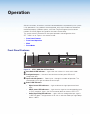
Operation .................................................17
Front Panel Features .......................................... 17
Front Panel Operation ........................................ 18
Switch Modes................................................ 18
Front Panel Lockout Mode
(Executive Mode) .......................................... 18
EDID .................................................................. 19
Reset Mode ....................................................... 19
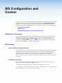
SIS Configuration and Control .................20
Host Device Connection .................................... 20
SIS Overview ..................................................... 20
Host and Device Communication ................... 20
Unsolicited Message ...................................... 20
Error Responses ............................................ 21
Command and Response Table Overview...... 21
Symbol Definitions ......................................... 21
Command and Response Tables for SIS
Commands ...................................................... 22
Input Commands ........................................... 22
Audio Configuration Commands .................... 22
Picture Adjustment Commands
(Analog Only) ................................................ 23
Preset Commands ......................................... 24
Auto memories (analog only) .......................... 24
EDID Commands ........................................... 24
Advanced Configuration Commands ............. 25
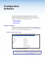
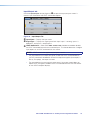
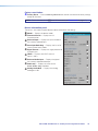
Configuration Software ............................28
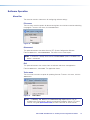
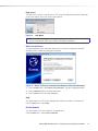
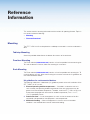
Software Installation........................................... 28
Software Download Center Page ................... 28
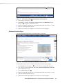
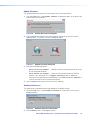
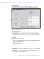
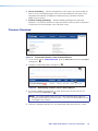
Software Product Page .................................. 29
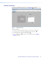
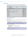
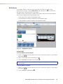
Software Connection ......................................... 30
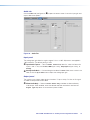
Software Operation............................................ 31
Menu Bar ...................................................... 31
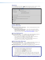
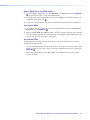
Device Settings .............................................. 34
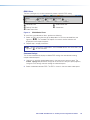
EDID Minder .................................................. 40
Reference Information ............................. 43
Mounting ........................................................... 43
Tabletop Mounting ......................................... 43
Furniture Mounting......................................... 43
Rack Mounting .............................................. 43
Firmware Download ........................................... 44

XTP T USW 103 4K Switcher • Contents xiii

XTP T USW 103 4K Switcher • Introduction 1
Introduction
This section contains general information about this guide and the Extron
XTP T USW 103 4K Switcher. Topics in this section include:
• Guide Overview
• Product Description
• Features
Guide Overview
This guide provides installation, operation, control, and reference information for the
XTP T USW 103 4K Switcher primarily in point-to-point applications.
NOTE: See an XTP matrix switcher user guide at www.extron.com for matrix
applications
In this guide, the terms “switcher” and “XTP T USW 103 4K” are used interchangeably to
refer to the XTP T USW 103 4K Switcher.
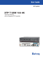
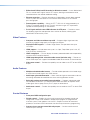
Product Description
The Extron XTP T USW 103 4K is a three input universal switcher with an integrated XTP
transmitter that sends HDMI, DisplayPort, or digitized analog video, audio, bidirectional
RS-232 and IR, and Ethernet up to 330 feet (100 meters) over a single shielded twisted
pair cable (STP). It is compliant with HDCP 2.2 (HDMI) or HDCP 1.3 (DisplayPort) standards
and supports video signal resolutions up to 4K. The XTP T USW 103 4K works with XTP
Systems for signal distribution and long-distance transmission between XTP devices.
The switcher can be powered locally or remotely through an Extron PI 140 Power Injector
(see Power Connection on page 14) or an XTP matrix switcher using an XTP input
board capable of remote powering 26-watt devices.
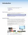
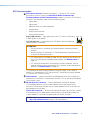
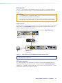
The following diagram shows one way the XTP T USW 103 4K can be integrated in an XTP
point-to-point application.
LAN
SIG LINK
XTP IN
POWER
12V
HDMI
1A MAX
Rx GTx
RS-232 IR
RxTx
−+−+
LR
1
2
OVER XTP
AUDIO
OFF
ON
S/PDIF
RESET
RS-232
Tx Rx G
REMOTERELAYS
OUTPUTS
AUDIO
Extron
XTP SR HD 4K
XTP Scaling Receiver
Extron
Cable Cubby 1200
Cable Access Enclosure
Ext
ron
XT
P T USW 103 4K
Swit
cher
SIG LINK
LAN
XTP OUT
POWER
XTP T USW 103 4K
12V
1.5 A MAX
AUDIO
123
RGB
HDMI DISPLAYPORT
HDMI OUT
Rx GTx
RS-232 IR
RxTx
G
CONTACT
G
RS-232
Tx Rx
123
TALLY OUT
+V
123
R
INPUTS
REMOTE
OVER XTP
USB CHARGER
125 VAC. 50-60 Hz 12A MAX
PRESSPRESS
PRESSPRESS
Shielded Twisted Pair Cable
up to 330' (100 m)
HDMI
HDMI DisplayPortVGAAudio
4K Display
MODEL 80
FLAT PANEL
Figure 1. Typical XTP T USW 103 4K Point-to-Point Application

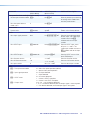
XTP T USW 103 4K Switcher • Introduction 2
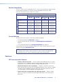
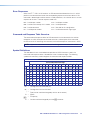
System Compatibility
The XTP T USW 103 4K is compatible with XTP systems, but the maximum video resolution
may be limited with different XTP devices. See the table below for maximum video
resolutions and refresh rates for various XTP systems.
Maximum Resolution and Refresh Rates for XTP Systems
Output
Non-4K 4K Fiber 4K Twisted
Pair
4K PLUS
Input
Analog 1920x1200
@ 60 Hz
1920x1200
@ 60 Hz
1920x1200
@ 60 Hz
1920x1200
@ 60 Hz
Non-4K Digital 2048x1080
@ 60 Hz
2048x1080
@ 60 Hz
2048x1080
@ 60 Hz
2048x1080
@ 60 Hz
4K Fiber 2048x1080
@ 60 Hz
4096x2160
@ 24 Hz
4096x2160
@ 24 Hz
4096x2160
@ 24 Hz
4K Twisted Pair 2048x1080
@ 60 Hz
4096x2160
@ 24 Hz
4096x2160
@ 30 Hz
4096x2160
@ 30 Hz
4K PLUS 2048x1080
@ 60 Hz
4096x2160
@ 24 Hz
4096x2160
@ 30 Hz
4096x2160
@ 60 Hz
Control Methods
To directly control the switcher, use one of the following methods:
• Front panel operation (see Operation on page 17)
• Simple Instruction Set (SIS) commands (see SIS Configuration and Control on
page 20)
• XTP Configuration Software (see Configuration Software on page 28).
Certain features can also be controlled through an XTP matrix switcher (see the XTP matrix
switcher user guide at www.extron.com).
NOTE: If the XTP T USW 103 4K is connected to an XTP matrix switcher, configure
it through the XTP matrix switcher (see the XTP matrix switcher user guide for SIS
commands or the XTP System Configuration Help File for software details).
Features
XTP interconnection Features
• Reliable cable infrastructure — Transmits video, audio, bidirectional RS-232 and IR,
and Ethernet over a shielded twisted pair cable to provide high reliability and maximum
performance on an economical and easily installed cable infrastructure.
• Shielded twisted pair cable compatibility — Supports a maximum transmission
distance of 330 feet (100 meters) for all compatible resolutions when used with shielded
twisted pair cable. Shielded twisted pair cabling with solid center conductor sizes of
24 AWG or better is recommended for optimal performance.
• Digital conversion of analog video and audio input signals — Digitizes analog
signals, ensuring that a reliable, high quality digital video signal is sent to the output
destination.

XTP T USW 103 4K Switcher • Introduction 3
• Bidirectional RS-232 and IR insertion for AV device control — Inserts bidirectional
RS-232 control and IR signals into the XTP output, allowing a remote device to be
controlled without the need for additional cabling.
• Ethernet extension — Reduces the amount of independent network drops required
within a system with centralized 10/100 Ethernet communication via an Ethernet
pass-through port.
• Remote power capability — Allows the XTP T USW 103 4K to be powered by an
Extron PI 140 power injector or an XTP matrix switcher using an XTP input board
capable of remote powering 26-watt devices.
• RJ-45 signal and link status LED indicators for XTP ports — Provides a means
for validating signal flow and operation from switcher to receiver, allowing quick
identification of connectivity issues.
Video Features
• Computer and video resolutions up to 4K — Supports digital signal extension,
maintaining superior image quality at the highest resolutions.
• DisplayPort SST support — Includes Single Stream Transport data rates up to
10.8 Gbps.
• HDMI support — Includes data rates up to 10.2 Gbps, Deep Color up to 12-bit, 3D,
and HD lossless audio formats.
• HDCP compliance — Ensures display of content-protected media and interoperability
with other HDCP-compliant devices.
• HDMI loop-through with selectable audio control (switcher only) — Features an
active HDMI output with support for embedded audio for connection to a local monitor.
• Video mute control — Provides the capability to mute video on the XTP or local HDMI
output.
Audio Features
• Multiple embedded audio formats — Provides reliable operation with a broad range
of multi-channel audio signals with HDMI sources.
• Audio input gain and attenuation — Allows the level of gain or attenuation to be set,
eliminating noticeable volume differences when switching between sources.
• Selectable analog stereo audio input embedding — Supports unbalanced audio
for extended transmission. This feature enables direct connection of separate stereo
audio signals from a laptop, Blu-ray Disc™ player, or other device.
• Audio mute control — Provides the capability to mute audio on the XTP or local HDMI
output.
Control Features
• Front panel USB configuration port
• RS-232 control — Enables the use of serial commands for complete control and
configuration via the Extron Windows
®
-based control program, or integrated into
a control system. Extron products use the SIS - Simple Instruction Set command
protocol, a set of basic ASCII commands that allow for quick and easy programming.
• Contact closure remote control with tally output — Can be used for external
control of input switching.

XTP T USW 103 4K Switcher • Introduction 4
General Features
• XTP compatibility — Provides a flexible signal switching and distribution solution that
is completely integrated, ensuring reliable routing of multiple digital and analog formats.
• Auto-input switching — Can be set to automatically switch to the highest or lowest
priority input with an active video signal for simplified operation.
• User-selectable HDCP authorization — Allows individual inputs to appear HDCP
compliant or non-HDCP compliant to the connected source, which is beneficial if the
source automatically encrypts all content when connected to an HDCP-compliant
device. Protected material is not passed in non-HDCP mode.
• EDID Minder — Automatically manages EDID communication between connected
devices. It ensures that all sources power up properly and reliably outputs content for
display.
• Key Minder — Authenticates and maintains continuous HDCP encryption between
input and output devices to ensure quick and reliable switching in professional AV
environments, while enabling simultaneous distribution of a single source signal to one
or more displays.
• HDCP visual confirmation — Provides a green signal when encrypted content is sent
to a non-compliant display.
• Internal color bars test patterns — Helps with setup and calibration.
• LED indicators — Provides visual indication of signal presence, HDCP, and power for
real-time feedback and monitoring of key performance parameters.
• LockIt HDMI cable lacing brackets — Secure HDMI cables to the HDMI connectors.
• 1U high, half rack width metal enclosure
• Highly reliable, energy-efficient external universal power supply included —
Provides worldwide power compatibility, with high demonstrated reliability and low
power consumption for reduced operating costs.

XTP T USW 103 4K Switcher • Installation 5
Installation
This section contains installation procedures for the XTP T USW 103 4K and wiring details.
Topics in this section include the following:
• Rear Panel Connectors
• Connection Details
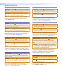
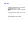
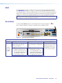
Rear Panel Connectors
SIG LINK
LAN
XTP OUT
POWER
XTP T USW 103 4K
12V
1.5 A MAX
AUDIO
123
RGB
HDMIDISPLAYPORT
HDMI OUT
Rx GTx
RS-232 IR
RxTx
G
CONTACT
G
RS-232
Tx Rx123
TALLY OUT
+V
123
R
INPUTS
LABCDE
FG H
IJK
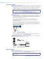
Input and Output Connectors Interconnection, Control, and Power
Connectors
A
Analog audio input connector
(see page 6)
B
Analog video input connector,
input 1 (see page 6)
C
HDMI input connector,
input 2 (see page 6)
D
DisplayPort input connector,
input 3 (see page 6)
E
HDMI output connector (see
page 6)
F
XTP output connector (see page 7)
G
LAN connector (see page 7)
H
RS-232 and IR Over XTP connector (see
page 7)
I
Contact closure connector (see page 8)
J
Tally Out connector (see page 8)
K
Remote RS-232 (see page 8)
L
Power connector and LED (see page 8)
Figure 2. XTP T USW 103 4K Rear Panel Connectors

XTP T USW 103 4K Switcher • Installation 6
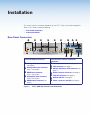
Inputs and Output Connections
NOTES:
• For HDMI cables, the maximum cable length is 15 feet (4.6 meters).
• Use Extron LockIt Cable Lacing Brackets to secure HDMI connectors to the device
(see HDMI Connection on page 9).
A
Analog audio input connector (see figure 2 on the previous page) — Connect an
analog stereo audio source to the 3.5 mm tip-ring-sleeve (TRS) jack.
Tip (+)
Sleeve ( )
Sleeve ( )
Ring (
-
)
Tip (+)
Audio Plugs.eps
RCA Connector
3.5 mm Stereo Plug Connector
(balanced)
Sleeve ( )
Ring (R)
Tip (L)
3.5 mm Stereo Plug Connector
(unbalanced)
Figure 3. Wiring for the Analog Audio Connector
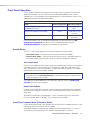
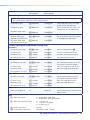
By default, audio input is selected automatically (see Audio input selection SIS
commands on page 22 to manually select audio inputs). When input 2 or 3 is
selected with automatic audio input selections, the switcher prioritizes embedded digital
audio. The table below shows the audio format that is sent over the XTP connection
when a specific audio format is not specified.
Default Audio Priorities
Selected
Video Input
Digital Embedded
Audio Present
Analog Audio
Present
Audio Sent Over XTP or
to the Local HDMI output
VGA N/A Yes Analog audio
VGA N/A No No audio
HDMI or DP Yes No Digital embedded audio
HDMI or DP Yes Yes Digital embedded audio
HDMI or DP No Yes Analog audio
HDMI or DP No No No audio
B
Analog video input connector — Connect a video source to the 15-pin HD
connector, labeled input 1. It accepts RGBHV video signals.
C
HDMI input connector — Connect a digital video source device to the female HDMI
connector, labeled input 2. It accepts HDMI, DVI (with an appropriate adapter), or dual
mode DisplayPort video sources.
D
DisplayPort input connector — Connect a digital video source device to the female
DisplayPort connector, labeled input 3.
E
HDMI output connector — Connect a digital video display to the HDMI output
connector for a local display of the selected input.

XTP T USW 103 4K Switcher • Installation 7
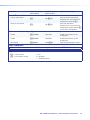
XTP Interconnection
F
XTP output connector (see figure 2 on page 5) — Connect an XTP twisted
pair receiver or matrix switcher (see Twisted Pair Cable Termination and
Recommendations for XTP Communication on page 10) to the RJ-45 XTP output
connector. The twisted pair cable carries the following signals:
• Digital video
• Digital audio
• Bidirectional RS-232 and IR commands
• Remote power
• Ethernet communication
• System communication
Signal LED indicator — Lights green when the XTP T USW 103 4K outputs
a video signal or a test pattern.
Link LED indicator — Lights yellow when XTP devices are connected and
communication is established.
ATTENTION:
• Do not connect this connector to a computer data or telecommunications
network.
• Ne connectez pas ce connecteur à un réseau de données informatiques ou à
un réseau de télécommunications.
• XTP remote power is intended for indoor use only. No part of the network that
uses XTP remote power should be routed outdoors (see Remote power on
page 16).
• XTP à distance est destiné à une utilisation en intérieur seulement. Aucune
partie du réseau qui utilise l’alimentation XTP à distance ne peut être routée en
extérieur (voir Remote power à la page 16).
This connector can also be used to power the switcher using a PI 140. To do so,
connect a PI 140 between this XTP port and the XTP connection of a locally powered
XTP receiver or XTP matrix switcher.
G
LAN connector — Connect a control or controlled device to the pass-through LAN
connector for 10/100Base-T Ethernet communication. LEDs on the connector indicate
link and activity status.
H
RS-232 Over XTP connector — To pass bidirectional serial signals between
XTP-compatible devices, connect a control device to the 5-pole captive screw
connector. The connector includes only the 2 poles labeled “RS-232” and shares the
ground pole with the IR poles.
IR Over XTP connector — To transmit and receive IR signals (up to 56 kHz), connect
a control device to the 5-pole captive screw connector. The connector includes the
2 poles labeled “IR” and shares the ground pole with the RS-232 poles.
NOTE: RS-232 and IR data can be transmitted simultaneously (see RS-232 and IR
Over XTP Communication on page 13 for wiring details).
SignalLink

XTP T USW 103 4K Switcher • Installation 8
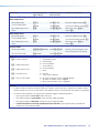
Control Connections
I
Contact closure connector (see figure 2 on page 5) — Connect Extron Show Me cables
or a locally-constructed contact closure device to the 4-pole captive screw connector.
The three left poles (1, 2, and 3) are used to select inputs 1 through 3 when momentarily
shorted to the ground pole. The closure accepts a momentary or latching contact.
NOTE: Auto switch mode must be disabled. To disable auto switch mode, use the
SIS commands (see the Auto switch mode commands on page 22) or the XTP
Configuration Software (see Auto-input Switching panel on page 38).
In conjunction with the tally connector, the currently selected input can be indicated.
J
Tally Out connector — To remotely identify the currently selected input, connect a
locally-constructed device into the 4-pole captive screw connector. Connect the power
wire for the device into the +V pin and connect the ground wire for each indicator in the
corresponding tally out pole (1, 2, or 3).
When an input is selected, by either contact closure or front panel selection, the
corresponding tally out pole shorts to ground, closing the circuit and lighting the
connected indicator (LED).
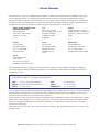
This connector can also be used with Extron Show Me cables and the contact closure
connector. For each Show Me cable, connect the red pigtail to the associated pole of
the contact closure connector and the black pigtail to the associated pole on the tally out
connector (see the diagram below).
G
CONTACT
G
RS-232
Tx Rx123
TALLY OUT
+V
123
Red Black
Show Me Cable
Pigtail
Figure 4. Show Me Cable Wiring
For more information and installation details about the Extron Show Me cables, see the
Show Me Cable Series Setup Guide at www.extron.com.
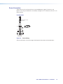
K
Remote RS-232 connector — Connect a host device to the 3.5 mm, 3-pole captive
screw connector for serial control of the switcher.
Do not tin the wires!
Controlling
Device
Ground (G)
Receive (Rx)
Transmit (Tx)
Ground (G)
Receive (Rx)
Transmit (Tx)
Bidirectional
Tx Rx G
RS-232
Figure 5. Remote RS-232 Wiring
Power Connection
L
Power connector and LED — Connect the external 12 V, 1.5 A power supply to the
2-pole captive screw connector (see Power Connection on page 14).
NOTE: The XTP T USW 103 4K can also be powered remotely (see Remote power
on page 16).

XTP T USW 103 4K Switcher • Installation 9
Connection Details
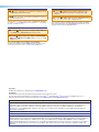
HDMI Connection
To secure the HDMI cable to the HDMI input or output connector, use an Extron LockIt
Cable Lacing Bracket and a tie wrap.
3
1
2
3
4
5
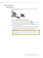
Figure 6. Installing the LockIt Cable Lacing Bracket
1. Plug the HDMI cable into the panel connection (see figure 6,
1
).
2. Loosen the HDMI connection mounting screw from the panel (
2
) enough to allow the
LockIt to be placed over it. The screw does not have to be removed.
3. Place the LockIt on the screw and against the HDMI connector (
3
), and then tighten
the screw to secure the bracket.
4. Loosely place the included tie wrap around the HDMI connector and the LockIt (
4
).
5. While holding the connector securely against the cable lacing bracket, use pliers or
similar tools to tighten the tie wrap, then remove any excess length (
5
).
ATTENTION:
• Connect and pull the tie wraps until they are secure. Do not overtighten.
• Connectez et tirez les serre-câbles jusqu’à ce qu’ils soient sécurisés. Ne pas
trop serrer.

XTP T USW 103 4K Switcher • Installation 10
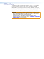
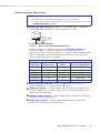
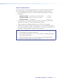
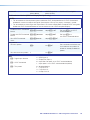
Twisted Pair Cable Termination and Recommendations for
XTP Communication
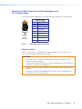
Use the following pin configurations for twisted pair cables used for XTP communication.
12345678
RJ-45
Connector
Inser
t Twisted
Pair Wires
Pins:
Pin
1
2
3
4
5
6
7
8
Wire color
White-green
Green
White-orange
Blue
White-blue
Orange
White-brown
Brown
Wire color
T568A T568B
White-orange
Orange
White-green
Blue
White-blue
Green
White-brown
Brown
TIA/EIA-T568B
Pin Wire Color
1 White-orange
2 Orange
3 White-green
4 Blue
5 White-blue
6 Green
7 White-brown
8 Brown
Figure 7. Twisted Pair Cable Termination
Supported cables
The XTP T USW 103 4K is compatible with shielded twisted pair (F/UTP, SF/UTP, and
S/FTP) and unshielded twisted pair (U/UTP) cables.
ATTENTION:
• Do not use Extron UTP23SF-4 Enhanced Skew-Free AV UTP cable or STP201
cable to link the XTP products.
• N’utilisez pas le câble AV Skew-Free UTP version améliorée UTP23SF d’Extron ou
le câble STP201 pour relier les produits XTP.
• To ensure FCC Class A and CE compliance, STP cables and STP connectors are
required.
• Afin de s’assurer de la compatibilité entre FCC Classe A et CE, les câbles STP et
les connecteurs STP sont nécessaires.

XTP T USW 103 4K Switcher • Installation 11
Cable recommendations
Extron recommends using the following practices for XTP communication to achieve full
transmission distances up to 330 feet (100 meters) and reduce transmission errors.
• Use the following Extron XTP DTP 24 SF/UTP cables and connectors for the best
performance:
• XTP DTP 24/1000 Non-Plenum 1000’ (305 m) spool 22-236-03
• XTP DTP 24P/1000 Plenum 1000’ (305 m) spool 22-235-03
• XTP DTP 24 Plug Package of 10 101-005-02
• If not using XTP DTP 24 cable, at a minimum, Extron recommends 24 AWG, solid
conductor, STP cable with a minimum bandwidth of 400 MHz.
• Terminate cables with shielded connectors to the TIA/EIA-T568B standard.
• Limit the use of more than two pass-through points, which may include patch points,
punch down connectors, couplers, or power injectors. If these pass-through points are
required, use shielded couplers and punch down connectors.
NOTE: When using STP cable in bundles or conduits, consider the following:
• Do not exceed 40% fill capacity in conduits.
• Do not comb the cable for the first 20 m, where cables are straightened, aligned,
and secured in tight bundles.
• Loosely place cables and limit the use of tie wraps or hook-and-loop fasteners.
• Separate twisted pair cables from AC power cables.

XTP T USW 103 4K Switcher • Installation 12
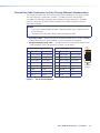
Twisted Pair Cable Termination for Pass-Through Ethernet Communication
The twisted pair cable used for Ethernet communication depends on the network speed.
The LAN connectors support both 10BASE-T (10 Mbps Ethernet) and 100BASE-T
(100 Mbps Fast Ethernet), half-duplex and full-duplex Ethernet connections. Terminate
the RJ-45 connectors for Ethernet communcation with straight-through or crossover
termination standards.
NOTES:
• Do not use standard telephone cables. Telephone cables do not support Ethernet
or Fast Ethernet.
• To avoid transmission errors, do not stretch or bend the cables.
• Crossover cable — Wire one end of the twisted pair cable with the T568A standard
and the other with the T568B standard. Use this to connect to a computer.
• Straight-through (patch) cable — Wire both ends of the twisted pair cable with the
T568B standard. Use this to connect to a switch, hub, or router.
Straight-Through Cable
Pin End 1 Wire End 2 Wire
1 White-orange White-orange
2 Orange Orange
3 White-green White-green
4 Blue Blue
5 White-blue White-blue
6 Green Green
7 White-brown White-brown
8 Brown Brown
Crossover Cable
Pin End 1 Wire End 2 Wire
1 White-green White-orange
2 Green Orange
3 White-orange White-green
4 Blue Blue
5 White-blue White-blue
6 Orange Green
7 White-brown White-brown
8 Brown brown
Figure 8. RJ-45 Pin Assignment
12345678
RJ-45 Connector
Insert T
wisted
Pair Wires
Pins:
Side View

XTP T USW 103 4K Switcher • Installation 13
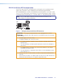
RS-232 and IR Over XTP Communication
The RS-232 and IR Over XTP connector passes serial signals (such as projector control
signals) and infrared data. To pass bidirectional serial command signals between
XTP-compatible devices, connect a control device to the three poles (Tx, Rx, and G) under
“RS-232” of the 5-pole captive screw connector. To transmit and receive IR signals, connect
a control device to the three poles (G, Tx, and Rx) under “IR.” The ground (G) pole is shared.
NOTE: RS-232 and IR data can be transmitted or received simultaneously (see
figure 9 below for wiring considerations).
Tx/Rx
Pins
RxTx
RS-232
RxTx
TxRx
RxTx
Custom
IR Device
RS-232 Device
G
G
G
IR
Figure 9. Wiring the RS-232 and IR Over XTP Connector
ATTENTION: The length of the exposed wires in the stripping process is critical.
ATTENTION : La longueur des câbles exposés est primordiale lorsque l’on entreprend
de les dénuder.
• The ideal length is 3/16 inch (5 mm).
• La longueur idéale est de 5mm (3/16inches).
• If the exposed portion is longer, the wires may touch, causing a short circuit
between them.
• S’ils sont trop longs, les câbles exposés pourraient se toucher et provoquer un
court circuit.
• If the exposed wires are shorter, they can be easily pulled out, even if tightly
fastened by the captive screws.
• S’ils sont trop courts, ils pourraient sortir, même s’ils sont correctement serrés
par les borniers à vis.
• Do not tin the wires. Tinned wire does not hold its shape and can become loose
over time.
• Ne pas étamer les câbles. Les câbles étamés ne sont pas aussi bien fixés dans les
terminaisons des connecteurs à vis captives et pourraient sortir.
La page est en cours de chargement...
La page est en cours de chargement...
La page est en cours de chargement...
La page est en cours de chargement...
La page est en cours de chargement...
La page est en cours de chargement...
La page est en cours de chargement...
La page est en cours de chargement...
La page est en cours de chargement...
La page est en cours de chargement...
La page est en cours de chargement...
La page est en cours de chargement...
La page est en cours de chargement...
La page est en cours de chargement...
La page est en cours de chargement...
La page est en cours de chargement...
La page est en cours de chargement...
La page est en cours de chargement...
La page est en cours de chargement...
La page est en cours de chargement...
La page est en cours de chargement...
La page est en cours de chargement...
La page est en cours de chargement...
La page est en cours de chargement...
La page est en cours de chargement...
La page est en cours de chargement...
La page est en cours de chargement...
La page est en cours de chargement...
La page est en cours de chargement...
La page est en cours de chargement...
La page est en cours de chargement...
La page est en cours de chargement...
-
 1
1
-
 2
2
-
 3
3
-
 4
4
-
 5
5
-
 6
6
-
 7
7
-
 8
8
-
 9
9
-
 10
10
-
 11
11
-
 12
12
-
 13
13
-
 14
14
-
 15
15
-
 16
16
-
 17
17
-
 18
18
-
 19
19
-
 20
20
-
 21
21
-
 22
22
-
 23
23
-
 24
24
-
 25
25
-
 26
26
-
 27
27
-
 28
28
-
 29
29
-
 30
30
-
 31
31
-
 32
32
-
 33
33
-
 34
34
-
 35
35
-
 36
36
-
 37
37
-
 38
38
-
 39
39
-
 40
40
-
 41
41
-
 42
42
-
 43
43
-
 44
44
-
 45
45
-
 46
46
-
 47
47
-
 48
48
-
 49
49
-
 50
50
-
 51
51
-
 52
52


Extron XTP T USW 103 4K Manuel utilisateur
- Catégorie
- Commutateurs vidéo
- Taper
- Manuel utilisateur
dans d''autres langues
- English: Extron XTP T USW 103 4K User manual
Documents connexes
-
Extron XTP R HD 4K Manuel utilisateur
-
Extron XTP T VGA Manuel utilisateur
-
-
Extron XTP T HWP 101 4K Manuel utilisateur
-
-
-
-
-
-