Eccotemp 45HI-NGV Manuel utilisateur
- Catégorie
- Chauffe-eau
- Taper
- Manuel utilisateur


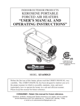
WARNING: If the information in these
instructions is not followed exactly, a re or
explosion may result causing property
damage, personal injury or death.
• Do not store or use gasoline or other
ammable vapors and liquids in the
vicinity of this or any other appliance.
• WHAT TO DO IF YOU SMELL GAS
- Do not try to light any appliance.
- Do not touch any electrical switch; do
not use any phone in your building.
- Immediately call your gas supplier
from a neighbor’s phone. Follow the gas
supplier’s instructions.
- If you cannot reach your gas supplier,
call the re department.
• Installation and service must be performed
by a qualied installer, service agency or
the gas supplier.

1
Product Support: Eccotemp.com/help-desk Shop Online: Eccotemp.com/products Store Locator: Eccotemp.com/locator
Phone: 866-356-1992 | Email: Support@eccotemp.com | Address: 315 - A Industrial RD Summerville, SC 29483
Use & Care Manual
With Installation Instructions for the Installer
Residential Outdoor Gas 140,00 BTU Max Input @ 6.8 GPM
Tankless Water Heater
WARNING: This water heater may not be suitable
for use in manufactured (mobile) homes! Please check
local code restrictions pertaining to permanent/xed installations in
manufactured homes in your area.
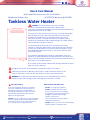
The purpose of this manual is twofold: one, to provide the installer
with the basic directions and recommendations for the proper
installation and adjustment of the water heater; and two, to
the owner-operator, to explain the features, operation, safety
precautions, maintenance and troubleshooting of the water heater.
This manual also includes a parts list.
It is imperative that all persons who are expected to install,
operate or adjust this water heater read the instructions carefully
so they may understand how to perform these operations. If you
don’t understand these instructions or any terms within it, seek
professional advice.
Any questions regarding the operation, maintenance, service or
warranty of this water heater should be directed to the seller from
whom it was purchased. If additional information is required, refer to
the section on If You Need Service.
Do not destroy this manual. Please read carefully and keep in a safe
place for future reference.
Recognize this symbol as an indication of Important Safety Information!
California Proposition 65 Warning: This product contains chemicals known to the
State of California to cause cancer, birth defects or other reproductive harm.
WARNING: If the information in these instructions is not followed exactly, a re or
explosion may result causing property damage, personal injury or death.
FOR YOUR SAFETY!
Improper installation, adjustment, alteration,
service or maintenance can cause property
damage, personal injury, or death. Refer to
this manual. Installation and service must be
performed by a qualied installer, service
agency or the gas supplier.
DO NOT store or use gasoline or other ammable
vapors or liquids or other combustible materials
in the vicinity of this or any other appliance. To
do so may result in an explosion or re.
WHAT TO DO IF YOU SMELL GAS
• DO NOT try to light any appliance.
• DO NOT touch any electrical switch;
do not use any phone in your building.
• Immediately call your gas supplier from
a neighbor’s phone. Follow the gas
supplier’s instructions.
• If you cannot reach your gas supplier,
call the re department.
• DO NOT return to your home until authorized by
the gas supplier or re department.

2
Product Support: Eccotemp.com/help-desk Shop Online: Eccotemp.com/products Store Locator: Eccotemp.com/locator
Phone: 866-356-1992 | Email: Support@eccotemp.com | Address: 315 - A Industrial RD Summerville, SC 29483
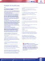
FOR YOUR RECORDS
Write the model and serial numbers here:
#_______________________________
#_______________________________
You can nd them on a label on the appliance
and/or packaging.
Staple sales slip or canceled check here.
Proof of the original purchase date is needed to
obtain service under the warranty.
READ THIS MANUAL
Inside you will nd many helpful hints on how
to use and maintain your water heater properly.
A little preventive care on your part can save
you time and money over the life of your water
heater. You’ll nd many answers to common
problems in the Troubleshooting Guide. If you
review the chart of Troubleshooting Tips rst,
you may not need to call for service.
READ THE SAFETY INFORMATION
Your safety and the safety of others are very
important. There are many important safety
messages in this manual and on your appliance.
Always read and obey all safety
messages.
This is the safety alert symbol.
Recognize
this symbol as an indication of
Important Safety Information! This
symbol alerts you
to potential hazards that can kill or hurt
you and others.
All safety messages will follow the safety alert
symbol and either the word “DANGER”,
“WARNING”, “CAUTION” or “NOTICE”.
These words mean:
DANGER - An imminently hazardous situation
that will result in death or serious injury.
WARNING - A potentially hazardous situation
that could result in death or serious injury
and/or damage to property.
CAUTION - A potentially hazardous situation
that may result in minor or moderate injury.
NOTICE: Attention is called to observe
a specied procedure or maintain a
specic condition.
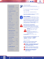
Safety Information
Safety Precautions .............3-6
LP Gas Models .......................5
Installation Instructions
Location ..............................7-9
Water Connections ...........9-10
Gas Supply............................10
Relief Valve...........................11
Leak Testing..........................12
High Altitude ........................12
Venting ................................12
Remote Control ..............13-14
Electrical Connection ...........15
Typical Installation ...............16
Pipe Insulation .....................17
Installation Checklist ...........18
Operating Instructions
Start Instructions ............19-20
Water Temperature ............21
Temperature Memory..........21
Care and Cleaning
Maintenance .......................22
Housekeeping .................22-23
Extended Shut-Down ...........23
Anti-Freezing........................23
Draining ...............................24
Troubleshooting Tips
Before You Call ....................25
Error Code Guide ................26

3
Product Support: Eccotemp.com/help-desk Shop Online: Eccotemp.com/products Store Locator: Eccotemp.com/locator
Phone: 866-356-1992 | Email: Support@eccotemp.com | Address: 315 - A Industrial RD Summerville, SC 29483
IMPORTANT SAFETY INFORMATION READ ALL
INSTRUCTIONS BEFORE USING
Be sure to read and understand the entire Use and Care Manual before attempting to install or
operate this water heater. It may save you time and money. Pay particular attention to the Safety
Instructions. Failure to follow these warnings could result in serious bodily injury or death. Should
you have problems understanding the instructions in this manual, or have any questions, STOP, and
get help from a qualied service technician, or the local gas utility.
DANGER!
PROPERLY INSTALL WATER HEATER
Failure to properly install the water heater outdoors as outlined in the Installation
Instructions in this manual can result in unsafe operation of the water heater. To
avoid the risk of re, explosion, or asphyxiation from carbon monoxide, never
operate this water heater unless it is installed properly and has an adequate
air supply for proper operation. Be sure to inspect the ue terminal for proper
installation at initial start-up; and at least annually thereafter. Refer to the Care
and Cleaning section of this manual for more information regarding ue terminal
inspection.
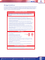
WARNING!
Gasoline, as well as other ammable materials and liquids (adhesives, solvents,
paint thinners etc.), and the vapors they produce are extremely dangerous. DO
NOT handle, use or store gasoline or other ammable or combustible materials
any where near or in the vicinity of a water heater or any other appliance. Be sure
to read and follow the labels on the water heater, as well as the warnings printed
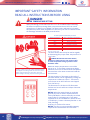
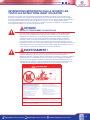
Vapors from ammable
liquids will explode and catch re
causing death or severe burns.
Do not use or store ammable products
such as gasoline, solvents or adhesives
In the same room or area near the
water heater.
Keep ammable products :
1. Far away from heater
2. In approved containers
3. Tightly closed
4. Out of children ‘s reach
Water heater has a main burner ame.
The main burner ame
1. Can come on at any time and
2. Will ignite ammable vapors.
Vapors:
1. Cannot be seen
2. Are heavier than air
3. Go a long way on the oor
4. Can be carried from other rooms to
the main burner ame by air currents.
Installation:
Do not Install water heater where ammable products will be stored or used
unless the main burner ame Is at least 18” above the oor. This will reduce, but
not eliminate, the risk of vapors being ignited by the main burner ame.
Read and follow water heater warnings and Instructions. If owners manual is
missing, contact the retailer or manufacturer.

4
Product Support: Eccotemp.com/help-desk Shop Online: Eccotemp.com/products Store Locator: Eccotemp.com/locator
Phone: 866-356-1992 | Email: Support@eccotemp.com | Address: 315 - A Industrial RD Summerville, SC 29483
IMPORTANT SAFETY INFORMATION
READ ALL INSTRUCTIONS BEFORE USING
DANGER!
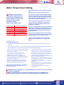
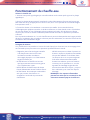
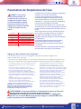
WATER TEMPERATURE SETTING
Safety and energy conservation are factors to be considered when selecting
the water temperature setting. Water temperatures above 125°F can cause
severe burns or death from scalding. The thermostat is adjusted to its lowest
temperature position when shipped from the factory. Be sure to read and follow
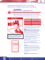
the warnings outlined on the label pictured below.
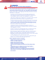
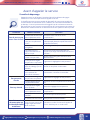
The chart shown above may be used as a guide
in determining the proper water temperature for
your home
DANGER: Households with small children,
disabled, or elderly persons may require a 120°F.
or lower temperature setting to prevent contact
with”HOT” water.
Maximum water temperature occurs while
burner is on. To nd water temperature being
delivered, turn on a hot water faucet and place a
thermometer in the water stream and read the
thermometer.
The temperature of the water at the outlet of
the water heater can be regulated by setting the
temperature on Remote Control . The remote
control was set at 110°F before it was shipped
from the factory.
The illustration to the bottom left illustrates
the Remote Control and how to adjust the water
temperature.
NOTICE: When this water heater is supplying
general purpose hot water requirements for
use by individuals, a thermostatically controlled
mixing valve for reducing point of use water
temperature is recommended to reduce the risk
of scald injury. Contact a licensed plumber or the
local plumbing
authority for further information.
NOTICE: The factory recommended operating
temperatures are between 90°F and 140°F.
Water Temperature
120°F
125°F
130°F
135°F
140°F
145°F
150°F
155°F
Time To Produce a Serious Burn
More than 5 minutes
1 1/2to 2 minutes
About 30 seconds
About 10 seconds
Less than 5 seconds
Less than 3 seconds
About 1 1/2 seconds
About 1 second
Time/Temperature Relationship in Scalds
Table courtesy of Shriners Burn Institute
Water temperature over 125°F can cause severe burns
instantly or death from scalds. Children, disabled and elderly
are at highest risk of being scalded. See instruction manual
before setting temperature at water heater. Feel water
before bathing or showering. Temperature limiting valves are

5
Product Support: Eccotemp.com/help-desk Shop Online: Eccotemp.com/products Store Locator: Eccotemp.com/locator
Phone: 866-356-1992 | Email: Support@eccotemp.com | Address: 315 - A Industrial RD Summerville, SC 29483
DANGER!
NATURAL GAS AND LIQUEFIED PETROLEUM MODELS
Both LP and natural gas have an odorant added to aid in detecting a gas leak.
Some people may not physically be able to smell or recognize this odorant. If you
are unsure or unfamiliar with the smell of LP or natural gas, ask the gas supplier.
Other conditions, such as “odorant fade”, which causes the odorant to diminish in
intensity, can also hide or camouage a gas leak. Always check with commercial
leak detector or soapy water.
• Gas detectors are recommended in LP and natural gas applications and
their installation should be in accordance with the detector manufacturer’s
recommendations and/or local laws, rules, regulations or customs.
• Water heaters utilizing LP gas are different from natural gas models. A natural
gas water heater will not function safely on LP gas and vice versa.
• No attempt should ever be made to convert the water heater from natural gas
to LP gas. To avoid possible equipment damage, personal injury or re, do not
connect the water heater to a fuel type not in accordance with the unit data
plate; propane for propane units and natural gas for natural gas units. These
units are not certied for any other fuel type.
• LP appliances should not be installed· below grade (for example, in a
basement) if such installation is prohibited by federal, state and/or local laws,
rules, regulations or customs.
• Propane or LP gas must be used with great caution. It is heavier than air and
will collect rst in lower areas making it hard to detect at nose level.
• Before attempting to light the water heater, make sure to look and smell for
gas leaks. Use a soapy solution to check all gas ttings and connections.
Bubbling at a connection indicates a leak that must be corrected. When smelling
to detect a gas leak, be sure to sniff near the oor also.
• It is recommended that more than one method, such as soapy solution, gas
detectors, etc., be used to detect leaks in gas applications.
Notice: If a gas leak is present or suspected:
• DO NOT attempt to nd the cause yourself.
• DO NOT try to light any appliance.
• DO NOT touch any electrical switch.
• DO NOT use any phone in your building.
• Leave the house immediately and make sure your family and pets leave
also.
• Leave the doors open for ventilation and contact the gas supplier, a
qualied service agency or the re department.
• Stay away from the house (or building) until the service call has been
made, the leak is corrected and a qualied agency has determined the
area to be safe.

6
Product Support: Eccotemp.com/help-desk Shop Online: Eccotemp.com/products Store Locator: Eccotemp.com/locator
Phone: 866-356-1992 | Email: Support@eccotemp.com | Address: 315 - A Industrial RD Summerville, SC 29483
IMPORTANT SAFETY INFORMATION READ ALL
INSTRUCTIONS BEFORE USING
FOR INSTALLATIONS I N THE STATE OF CALIFORNIA
California Law requires that residential water heaters must be braced, anchored
or strapped to resist falling or horizontal displacement due to earthquake
motions.For residential water heaters up to 52 gallon capacity, a brochure with
generic earthquake bracing instructions can be obtained from: Ofce of the State
Architect, 400 P Street, Sacramento, CA 95814 or you may call 916-445-8100 or
ask a water heater dealer.
However, applicable local codes shall govern installation. For residential water
heaters of a capacity greater than 52 gallons or tankless style, consult the local
building jurisdiction code for acceptable bracing procedures.
SAFETY PRECAUTIONS
Have the installer show you the location of the gas shut-off valve and how to shut
it off if necessary. Turn off the manual shut-off valve if the water heater has been
subjected to overheating, re, ood, physical damage or if the gas supply fails to
shut off.
• Read this manual entirely before installing or operating the water heater.
• Use this appliance only for its intended purpose as described in this
Use and Care Manual.
• Be sure your appliance is properly installed in accordance with local codes
and the provided installation instructions.
• Part of your water heater unless it is specically recommended in this manual.
All other servicing should be referred to a qualied technician.
READ AND FOLLOW THIS SAFETY INFORMATION CAREFULLY .
SAVE THESE INSTRUCTIONS
WARNING!
For your safety, the information in this manual must be followed to
minimize the risk of re or explosion, electric shock, or to prevent property
damage, personal injury, or loss of life.
This water heater must be installed in accordance with these instructions, local codes, utility company requirements, and/
or in the absence of local codes, use the latest edition of the American National Standard/National Fuel Gas Code. A copy
can be purchased from either the American Gas Association, 400 North Capitol Street Northwest, Washington, DC 20001
as ANSI standard Z223.1 or National Fire Protection Association, 1 Batterymarch Park, Quincy, MA 02269 as NFPA 54. In
Canada, the latest edition of the CSA B149.1 Natural Gas and Propane Installation, and the Canadian Electrical Code, CSA
C22.1Part1, in the absence of local codes.

7
Product Support: Eccotemp.com/help-desk Shop Online: Eccotemp.com/products Store Locator: Eccotemp.com/locator
Phone: 866-356-1992 | Email: Support@eccotemp.com | Address: 315 - A Industrial RD Summerville, SC 29483
The water heater must be located so it is not
subject to physical damage, for example, by
moving vehicles, area ooding, etc.
The water heater must be installed vertically
with the water, gas, and power connections
on the underside, pointing toward the ground.
Failure to properly install the water heater
outdoors as outlined in this manual can result
in unsafe operation.
Hot and cold water lines should be insulated
to conserve water and energy.
DO NOT install water heater where subject to
vibrations.
DO NOT install the water heater in
Recreational Vehicles, Mobile Homes, Boats
and other Watercraft.
DO NOT install the water heater near vents
for heating or cooling. A minimum of 4 feet
should be maintained.
If the clearances stated on the Instruction/
Warning Label, located on the front panel
of the heater differ, install the water heater
according to the clearances stated on the label.
Location
This water heater is for OUTDOOR
installation ONLY!
Make sure before installation that the gas
type you will use is the same type on the
data plate.
The water heater unit should be installed by
professionals from your local gas company.
Please don’t attempt installation by yourself.
Improper installation may cause failure or
dangerous conditions such as gas leaking or
explosion.
This water heater is an outdoor model and
must be mounted on a vertical wall. It must
not be installed indoors or in a conned
space. The water heater should be installed
close to the most frequently used outlet and
its position chosen with safety and service in
mind.
Make sure people (particularly children,
disabled, and elderly) will not touch the
hot water outlet or the ue terminal. The
ue terminal and air inlet must be clear of
obstruction and shrubbery.
If installed in a public corridor, please assure
that the surrounding area is free of debris,
obstruction and ammable materials.
The unit must be installed on a re retardant
area, and must be away from all ammable
materials. Clearance should be 1.75 ft to the
left and right side of ammable materials,
and 6.75 ft to the front.
The unit should be installed in open area
where strong currents are not prevalent
This unit is of high power and will consume
a lot of oxygen when working, so the
installation area must be well ventilated, and
air in and out of the area has no blockage.
The outdoor unit should not be installed in a
corridor with rooms on the both sides or in
the closed corridor.
Take measures to avoid direct wind, rain
and snow. The installation area should be
constructed of re retardant materials. The
power socket connecting the water heater
should be properly grounded.
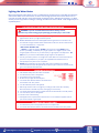
Installing the water heater
WARNING: Combustible construction
refers to adjacent walls and ceilings and
should not be confused with combustible
or ammable products and materials.
Combustible and/or ammable products
and materials should never be stored in
the vicinity of this or any gas appliance.

8
Product Support: Eccotemp.com/help-desk Shop Online: Eccotemp.com/products Store Locator: Eccotemp.com/locator
Phone: 866-356-1992 | Email: Support@eccotemp.com | Address: 315 - A Industrial RD Summerville, SC 29483
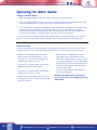
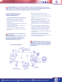
Proper operation of the water heater requires air for combustion and ventilation. Provisions for
combustion and ventilation air must comply with referenced codes and standards.
Combustion and Ventilation Air
This water heater is for OUTDOOR installation ONLY.
It must NOT be installed indoors or in a conned space.
Installing the water heater
Corrosive Atmospheres
The air in beauty shops, dry cleaning establishments, photo
processing labs, and storage areas for liquid and powdered
bleaches or swimming pool chemicals often contain such
halogenated hydrocarbons.
An air supply containing halogenated hydrocarbons may be safe
to breathe, but when it passes through a gas ame corrosive
elements are released that will shorten the life of any gas
burning appliance.
Propellants from common spray cans or gas leaks from A/ C and
refrigeration equipment are highly corrosive after passing through
a ame.
The water heater warranty is voided when failure of the heater is
due to operation in a corrosive atmosphere.
NOTICE: The water heater
should not be installed near
an air supply containing
halogenated hydrocarbons.
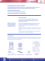
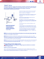
Inspect Shipment
Inspect the water heater for possible damage. Check the markings on the rating plate of the water
heater to be certain the type of gas supplied corresponds to the water heater requirements. Verify
all included parts are present (see below).
2

9
Product Support: Eccotemp.com/help-desk Shop Online: Eccotemp.com/products Store Locator: Eccotemp.com/locator
Phone: 866-356-1992 | Email: Support@eccotemp.com | Address: 315 - A Industrial RD Summerville, SC 29483
• When the water is supplied from a water
supply tank, the height of the tank and the
diameter of the pipes and their relation to
water pressure, should be taken into
consideration. Gravity water pressure is
not recommended.
NOTICE: If the water ow resistance of a
shower head is too high, the burner in the
water heater will fail to ignite. Keep the
shower head clean from debris that could
cause additional pressure drop.
NOTICE: If using mixing valves on the outlet,
choose one which prevents cold water
pressure from overcoming hot water line
pressure.
IMPORTANT: Do not apply heat to the HOT
or COLD water connections. Any heat applied
to the water supply ttings will permanently
damage the internal components of the water
heater.
Water Supply Connections
Plumbing should be carried out by a qualied
plumber in accordance with local codes.
Use approved plumbing materials and tools only.
To conserve energy and to prevent freezing,
insulate both cold and hot water supply lines.
DO NOT cover the drain valves.
To ensure proper operation of the water
heater, the following water pressure
guidelines should be followed:
• Operation of the water heater requires the
minimum water pressure of 14 psi and a
minimum water ow rate of 0.75 gpm.
• Additional water pressure is required for
long pipe runs and outlet tting(s) water
pressure drops.
• To maintain proper performance, ensure
sufcient water supply pressure. The
Required Water Pressure = Min. Operating
Water Pressure (14 psi) + Pipe Pressure
Loss + Faucet and Shower Pressure Loss +
Safety Margin (more than 5 psi).
• To supply hot water to upper oors,
additional water pressure (0.44 psi/ft)
must be ensured.The measurement should
be calculated by the distance between the
water inlet of the water heater (ground
level) to the hot water faucet (upper oor level).
• Well water systems should be set at a
range of 50-60 psi.
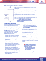
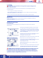
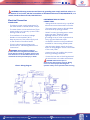
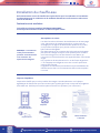
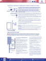
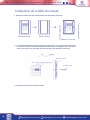
Mounting the Water Heater
Make sure the location of the appliance allows for easy access
and operation.
In case of dry wall or concrete wall use dry wall anchors or lag bolts.
The water heater requires 120VAC/ 60Hz. Have a receptacle with
ground terminal near the water heater. The length of the power
supply cord is 5 feet.
Drill the holes as per the sizes in the gure to the left, put 2
expansion screws into the top holes, and 2 rubber screws into the
bottom holes.
Hang up the water heater unit, tighten the expansion screws, and
put 2 wood thread screws into the bottom holes.
CAUTION: Reinforcement of the wall is
required in case the wall is not strong enough
to hold the appliance.
CAUTION: This water heater must
only be used with the following water
supply system conditions:
• With clean, potable water free of
corrosive chemicals, sand, dirt, or
other contaminates.
• With inlet water temperatures
above 32°F, but not exceeding 120°F.
• Free of lime and scale deposits.
• DO NOT reverse the hot and cold
water connections. The water
heater will not operate.

10
Product Support: Eccotemp.com/help-desk Shop Online: Eccotemp.com/products Store Locator: Eccotemp.com/locator
Phone: 866-356-1992 | Email: Support@eccotemp.com | Address: 315 - A Industrial RD Summerville, SC 29483
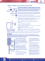
Water Supply Connections Continued
If a water heater is installed in a closed water supply system, such as one
having a backow preventer in the cold water supply line, means shall be
provided to control thermal expansion. Contact the water supplier or local
plumbing inspector on how to control this situation. Install a shutoff valve
near the inlet of the water heater for service and draining purposes.
Before connecting the water supply pipe to the water heater, open
the shutoff valve ·and clean out sand, debris, air, caulking material,
etc. inside the pipe. Connect to the water inlet, then check water ow.
Close the shutoff valve and clean the water lter.
Be sure to connect the water inlet and the hot water outlet as shown
on the water heater. If reversed, the water heater will not function.
Installation of unions or exible copper connections are
recommended on the HOT and COLD water lines, so that the water
heater may disconnect easily for servicing if necessary.
Install a Check Valve between the water heater and the water
shutoff
valve. (See illustration to the top left).
In regards to the HOT WATER OUTLET:
Connections between the water heater and point(s) of use should be
as short and direct as possible.
DO NOT use lead or non-approved plastic pipe.
NOTICE: The ow rate of hot water may vary when more than two
faucets (appliances, xtures, etc.) are being used simultaneously.
NOTICE: The pipes MUST be completely drainable. If the hot water faucets are located at a point higher
than the water heater, place a drain valve at the lowest point (see illustration to the bottom left).
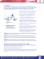
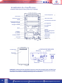
Gas Supply
WARNING: Do not attempt to convert this water heater for use with a different type of gas
other than the type shown on the rating plate. Such conversion could result in hazardous operating
conditions. Please have a professional connect the gas pipe.
A Manual Gas Appliance Shutoff
Valve must be installed at the gas
connection of the water heater at the
time of installation (see diagram to
the left). The branch gas supply line to
the water heater should be clean black
steel pipe or other approved gas piping
material.
A ground joint union or ANSI design
certied semi-rigid or exible gas
appliance connector should be
installed in the gas line close to the
water heater. The National Fuel Gas
Code (NFGC) mandates a manual gas
shut-off valve: See (NFGC) for complete
instructions.
If exible connectors are used, the
maximum length shall not exceed 36”.
If lever type gas shut offs are used,
they shall be T-Handle type.
Compound used on the threaded
joints of the gas piping must be of
the type resistant to the action of LP
gas. Use compound sparingly on male
threads only.
A sediment trap should be installed
at the bottom of the gas line.
Do not use excessive force (over
31.5 ft lbs.) in tightening the pipe,
particularly if pipe-tape compound
is used, as the unit may be damaged.
The inlet gas pressure to the water
heater must not exceed 10.5 “ w.c.
for natural or 14” w.c. for LP gas. For
purposes of input adjustment, the
minimum inlet gas pressure (with
main burner on) is shown on the
water heater rating plate. If high or
low gas pressures are present, contact
your gas supplier for correction.

11
Product Support: Eccotemp.com/help-desk Shop Online: Eccotemp.com/products Store Locator: Eccotemp.com/locator
Phone: 866-356-1992 | Email: Support@eccotemp.com | Address: 315 - A Industrial RD Summerville, SC 29483
Relief Valve
• The pressure rating of the relief valve must not exceed
150 psi, the maximum working pressure of the water
heater as marked on the rating plate.
• The BTUH rating of the relief valve must equal or exceed
the BTUH input of the water heater as marked on its
rating plate.
• No valve of any type should be installed between the
relief valve and the water heater.
• Discharge from the relief valve should be piped to a
suitable drain to eliminate potential water damage. Piping
used should be of a type approved for the distribution of
hot water.
• Hot and cold water lines should be insulated up to the
water heater.
• The discharge line must be NO SMALLER than the outlet
of the valve and must pitch downward to allow complete
drainage (by gravity) of the relief valve and discharge line.
• The end of the discharge line should not be threaded or
concealed and should be protected from freezing. No
valve of any type, restriction or reducer coupling should
be installed in discharge line.
NOTICE: Local codes govern the installation of relief valves. If local codes require that a temperature
and pressure relief valve should be installed the manufacturer recommends a type 40XL Watts T&P
relief valve or an equivalent model be used.
NOTICE: Manual operation of relief valves should be performed at least once a year. Turn off the
electrical power and gas shutoff valve. Lift and release lever on the relief valve and check the manual
operation of the relief valve. You should take precaution to avoid contact with the hot water coming
out of the relief valve and to prevent water damage.
NOTICE: If the relief valve on the system discharges periodically, this may be due to thermal expansion
in a closed water supply system. Contact the water supplier or local plumbing inspector on how to
correct theis situation. Do not plug the relief valve.
A new pressure relief valve, complying with the Standard for relief Valves and Automatic Gas Shut-Off Devices
for Hot Water Supply Systems, ANSI Z21.22, must be installed at the hot water outlet connection of the water
heater at the time of installation. Local codes shall govern the installation of relief valves.
For safe operation of the water heater, be sure that:
NOTICE: The above illustrates
a pressure only relief valve.
If local codes require a
combination temperature
and pressure relief valve be
installed, an extension piece
may be needed.
Pressure Testing the Gas Supply System
WARNING: Install a gas pressure regulator, in the gas supply line, which does not exceed the
maximum supply pressure.
DO NOT use an industrial type gas regulator.
Failure to isolate heater during pressure test can damage internal components voiding warranty. The water
heater must be isolated from the gas piping system by closing the manual gas shut-off valve during any pressure
testing of the gas supply piping at pressures equal to or less than 1/2 psi (14’w.c.).

12
Product Support: Eccotemp.com/help-desk Shop Online: Eccotemp.com/products Store Locator: Eccotemp.com/locator
Phone: 866-356-1992 | Email: Support@eccotemp.com | Address: 315 - A Industrial RD Summerville, SC 29483
Leak Testing
WARNING: Never use an open ame to test for gas leaks, as property damage, personal
injury, or death could result.
The water heater and its gas connections must be leak tested at normal operating pressures before
it is placed in operation.
• Turn on the gas shut-off valve(s) to the water heater.
• Use a commercial leak detector or soapy water solution to test for leaks at all connections and ttings.
Bubbles indicate a gas leak that must be corrected.
The factory connections should also be leak tested after the water heater is placed in operation.
High Altitude
Ratings of gas appliances are based on sea level operation and need not be changed for installations at
elevations up to 2,000 feet.
Unit not recommended for elevations in excess of 2,000 feet
Installing the water heater.
Flue Terminal Location
The location of the vent terminal depends on the following minimum clearances and considerations
(see illustration):
• Twelve (12) inches above grade level and above normal snow levels.
• Four (4) feet below, or four (4) feet horizontally from any door,
window, soft, under eave vent or gravity air inlet to the building
or other appliances, or from gas or electric meters. Do not locate
vent above walkways, doors, windows, air inlets, gas or electric
meters or other equipment.
• Ten (10) feet from any forced air inlet to the building. Any fresh or
make-up air inlet such as for a dryer or furnace area
is considered to be a forced air inlet.
• Eighteen (18) inches from an inside corner formed by two exterior walls.
• DO NOT install vent terminal under any patio or deck.
• To help prevent moisture from freezing on walls and under eaves,
do not locate vent terminal on the side of a building
with prevailing winter winds.
• DO NOT locate vent terminal too close to shrubbery, as ue
gases may damage them.
• Caulk all cracks, seams and joints within six (6) feet of vent terminal.
• All painted surfaces should be primed to lessen the chance of
physical damage. Painted surfaces will require maintenance.
Additional Considerations
WARNING : Moisture in the ue gas will condense as it leaves the vent terminal. In cold weather
this condensate can freeze on the exterior wall, under the eaves and on surrounding objects.
Some discoloration to the exterior of the building is to be expected. However, improper location
or installation can result in severe damage to the structure or exterior nish of the building. Code
requirements are subject to change and may vary by location.

13
Product Support: Eccotemp.com/help-desk Shop Online: Eccotemp.com/products Store Locator: Eccotemp.com/locator
Phone: 866-356-1992 | Email: Support@eccotemp.com | Address: 315 - A Industrial RD Summerville, SC 29483
WARNING : Field wiring connections and electrical grounding must comply with local codes, or in
the absence of local codes, with the latest edition of the National Electrical Code, ANSI/NFPA 70, or in
Canada, Canadian Electrical Code, CSA C22.1 Part 1
Remote Control Installation
The following are considerations for determining the location of the remote control(s):
• Avoid areas where the remote control(s)
may be subjected to oil and/or steam from
cooking.
• Avoid areas where chemical agents (such as
thinner, benzine and alkaline) are used.
• Avoid areas of direct sunlight.
• The MAXIMUM distance between the water
heater and the remote control(s) installation
location is limited to 50 feet.
• No other manufacturer’s controls are
suitable for use with this water heater.
• DO NOT attempt to disassemble the
remote control.
• DO NOT install any remote control outdoors.
• Place remote control(s) out of children’s reach.
• The remote control(s) can be installed in
convenient locations such as the kitchen,
laundry room, or utility room.
• The included remote control can be placed in
a convenient location in a bathroom, however,
AVOID areas where water may come into
contact with the control(s).
• Avoid areas where the remote control(s
may be exposed to heat, e.g. stove ranges or
heaters.
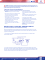
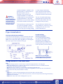
Remote control - Connection, Installation and Set
(For Panel Control/Remote Control and Remote Control units)
Panel Control/Remote Control and Remote Control units will work with either one or two
remote controls. If two remotes are desired, a wire connector will need to be provided. To
connect the remote control:
1. For one control: Plug the aviation joint into the socket directly on the water heater
(see illustration below)
2. For two controls: First, cut off the aviation joints on the two controllers, plug one into
the socket on the water heater (length is dependent on your requirements), and throw away
the other. Then connect the wires of the aviation joint to the inlet wire of the connector, and
connect the two remote control to the outlet wires of connector.

14
Product Support: Eccotemp.com/help-desk Shop Online: Eccotemp.com/products Store Locator: Eccotemp.com/locator
Phone: 866-356-1992 | Email: Support@eccotemp.com | Address: 315 - A Industrial RD Summerville, SC 29483
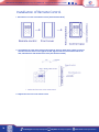
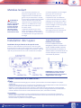
Installation of Remote Control
1. Remove the front cover of the Remote Control. (See illustration below)
2. At installation site, mark and screw two holes with 0.24” with 1.2” depth. Insert 2 rubber screws into
the holes. Place the remote control against the wall, align the holes of control with the holes in the
wall, and fasten them with wood thread screws. (See illustration below)
3. Replace the front cover on the remote control.

15
Product Support: Eccotemp.com/help-desk Shop Online: Eccotemp.com/products Store Locator: Eccotemp.com/locator
Phone: 866-356-1992 | Email: Support@eccotemp.com | Address: 315 - A Industrial RD Summerville, SC 29483
HARDWIRING THE ELE CTRICAL
CONNECTIONS:
• Wiring should be carried out by a qualied
electrician in accordance with local codes.
• The water heater requires 120 VAC/60Hz
and should be properly grounded.
• DO NOT connect grounding wire to water
pipes, gas pipes, telephone cables,
lightning conductor circuits and to
grounding circuit of other equipment that
carry a ground-fault interrupter.
• An ON/OFF switch must be provided and
installed for the incoming 120VAC power.
• Wire the water heater exactly as shown
below. A wiring diagram is also found inside
of the cover panel.
• A green screw is provided in the junction
box for grounding connection.
• Connect the live wire to black leg wire and
the neutral wire to the white neutral wire.
Electrical Connection
POWER CORD:
• The electric power supply requirement for
this water heater is 120 VAC/60HZ, 2 Amps.
• The water heater comes with a three (3) pin
power supply cord. Use only a power outlet
with a ground terminal.
• The installation of an electric leakage
breaker is recommended. (GFCI)
• Keep any excess of the power supply cord
on the outside of the water heater.
• If local codes require hardwiring, see
instructions for “Hardwiring the Electrical
Connections”.
WARNING :Field wiring connections and electri cal grounding must comply with local codes, or in
the absence of local codes, with the la test edition of the National Electrical Code,ANSI/NFPA 70, or in
Canada, Canadi an Electrical Code, CSA C22.1Part1.
WARNING: Shock hazard line voltage is
present. Before servicing the water heater, turn
off the electrical power to the water heater at the
main disconnect or circuit breaker. Failure to do so
could result in severe personal injury or death.
CAUTION: Label all wires prior to
disconnection when servicing controls. Wiring
errors can cause improper and dangerous
operation. Verify correct operation after servicing.
Electric Wiring Diagram

16
Product Support: Eccotemp.com/help-desk Shop Online: Eccotemp.com/products Store Locator: Eccotemp.com/locator
Phone: 866-356-1992 | Email: Support@eccotemp.com | Address: 315 - A Industrial RD Summerville, SC 29483
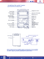
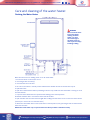
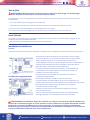
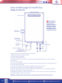
Installing the water heater.
Typical Installation ( Some Items May Not Apply)
NOTICE: The National Fuel Gas Code (NFGC) mandates a manual gas shut- off valve: See (NFGC)
for complete instructions. Local codes or plumbing authority requirements may vary from the
instructions or diagrams provided and take precedent over these instructions.

17
Product Support: Eccotemp.com/help-desk Shop Online: Eccotemp.com/products Store Locator: Eccotemp.com/locator
Phone: 866-356-1992 | Email: Support@eccotemp.com | Address: 315 - A Industrial RD Summerville, SC 29483
Insulation blankets, available to the
general public, for external use on
gas water heaters are not
necessary. The purpose of an
insulation blanket is to reduce the
standby heat loss encountered with
storage tank heaters. This water
heater does not store water making
an insulation blanket unnecessary.
The manufacturer’s warranty does
not cover any damage or defect
caused by installation, attachment
or use of any type of energy saving
or other unapproved devices
(other than those authorized by
the manufacturer) into, onto or in
conjunction with the water heater.
The use of unauthorized energy
saving devices may shorten the
life of the water heater and may
endanger life and property.
The manufacturer disclaims any
responsibility for such loss or injury
resulting from the use of such
unauthorized devices.
WARNING: If
local codes require
external application of
insulation blanket kits
the manufacturer’s
instructions included
with the kit must be
carefully followed.
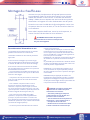
Hot and Cold Pipe
Insulation Installation
For increased energy efciency,
use pipe insulation. Please install
the insulation, according to the
illustrations above, making sure to
insulate all the way to the top. Do not
cover any drain or pressure valve(s).
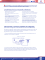
Pipe Installation
Inlet Pipe and Outlet Pipe Installation
Use pressure resistant pipe to connect the inlet and outlet
water pipes of the water heater and the local water pipe
(Make sure to place the rubber ring).Before connecting the
inlet water pipe, ush the inside of the pipe.
NOTICE: The hot and cold pipes
should be insulated as shown help to
provide additional freeze protection
During Installation of this water heater…
Do’s
• DO check inlet gas pressure to ensure that it is within the range specied on the rating plate.
• DO provide adequate air for combustion and ventilation as discussed in the Use & Care Manual and the
National Gas Code (CAN/CGA B 149 in Canada).
• DO maintain proper clearances to combustibles as specied by applicable code.
• DO ensure that the ue terminal location complies with the guidelines found in the Use & Care Manual and
National Fuel Gas Code (CAN/CGA B 149 in Canada).
Dont’s
• DON’T block or restrict Air Intake Opening located on the back side of the water heater.
• DON’T remove the front cover unless absolutely necessary. This should only be done after being examined by a
qualied service technician.
• DON’T install this product where standing water may occur.
La page charge ...
La page charge ...
La page charge ...
La page charge ...
La page charge ...
La page charge ...
La page charge ...
La page charge ...
La page charge ...
La page charge ...
La page charge ...
La page charge ...
La page charge ...
La page charge ...
La page charge ...
La page charge ...
La page charge ...
La page charge ...
La page charge ...
La page charge ...
La page charge ...
La page charge ...
La page charge ...
La page charge ...
La page charge ...
La page charge ...
La page charge ...
La page charge ...
La page charge ...
La page charge ...
La page charge ...
La page charge ...
La page charge ...
La page charge ...
La page charge ...
La page charge ...
La page charge ...
La page charge ...
La page charge ...
La page charge ...
La page charge ...
La page charge ...
La page charge ...
La page charge ...
-
 1
1
-
 2
2
-
 3
3
-
 4
4
-
 5
5
-
 6
6
-
 7
7
-
 8
8
-
 9
9
-
 10
10
-
 11
11
-
 12
12
-
 13
13
-
 14
14
-
 15
15
-
 16
16
-
 17
17
-
 18
18
-
 19
19
-
 20
20
-
 21
21
-
 22
22
-
 23
23
-
 24
24
-
 25
25
-
 26
26
-
 27
27
-
 28
28
-
 29
29
-
 30
30
-
 31
31
-
 32
32
-
 33
33
-
 34
34
-
 35
35
-
 36
36
-
 37
37
-
 38
38
-
 39
39
-
 40
40
-
 41
41
-
 42
42
-
 43
43
-
 44
44
-
 45
45
-
 46
46
-
 47
47
-
 48
48
-
 49
49
-
 50
50
-
 51
51
-
 52
52
-
 53
53
-
 54
54
-
 55
55
-
 56
56
-
 57
57
-
 58
58
-
 59
59
-
 60
60
-
 61
61
-
 62
62
-
 63
63
-
 64
64


Eccotemp 45HI-NGV Manuel utilisateur
- Catégorie
- Chauffe-eau
- Taper
- Manuel utilisateur
dans d''autres langues
- English: Eccotemp 45HI-NGV User manual
Documents connexes
-
Eccotemp EL22i-NGH Manuel utilisateur
-
Eccotemp iE11 Manuel utilisateur
-
Eccotemp L5 Pump/Strainer Manuel utilisateur
-
-
-
-
Eccotemp CEL 5 Manuel utilisateur
-
Eccotemp EZKIT Manuel utilisateur
-
-
Autres documents
-
Rheem XP75T12UHN100U0 Mode d'emploi
-
-
-
HTP Everlast Electric Mini Tank Water Heater Manuel utilisateur
-
Ariston ANDRIS RS 2.5U 1.4KW Manuel utilisateur
-
-
GSW Chauffe-eau au gaz à évacuation forcée Manuel utilisateur
-
 Dyna-Glo Delux KFA650DGD Guide d'installation
