

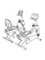
Before attempting to operate your Lifecycle 9500HR exercise bike, it is imperative that you
familiarize yourself with the contents of the Operation Manual. If your exercise bike does not
respond as described in the operation manual contact the nearest Life Fintness Customer
Service Center as listed in the operation manual.
Avant d'essayer de mettre en marche le vélo d'entraînement Lifecycle 9500HR, il est impératif
de vous familiariser avec le contenu du manuel d'utilisation. Si votre vélo ne fonctionne pas de
la manière décrite dans le manual d’utilisation, prenez contact avec le Centre de Service à la
Clientèle de Life Fitness dont le numéro figure dans le manual d’utilisation.
Antes de intentar poner en funcionamiento su bicicleta de ejercicio 9500HR, es imperativo que
usted se familiarice con el contenido del Manual de Operación. Si su bicicleta de ejercicio no
responde de la manera que se describe en el manual de operacon, entonces póngase en
contacto con el Centro de Servicio Life Fitness más cercano de los que se encuentran en la
lista del manual de operacon.
10601 West Belmont Avenue
l
Franklin Park, IL 60131
800.351.3737 or 847.451.0036
Copyright 1999 Brunswick Corporation. All rights reserved. Life Fitness, Lifecycle, Lifepulse, and FlexDeck are registered trademarks
and Heart Rate Zone Training, Lifespring and “Rely on it” are trademarks of Brunswick Corporation.
M051-00K20-B155
1/99
PRE-OPERATION CHECKLIST
4 Insure that the STABILIZER BAR and HANDLEBAR BOLTS are tight.
4 Make sure the exercise bike is properly leveled and stable.
4 Confirm the display console is set to english or metric units.
(See Optional Settings ENG/MET in Operation Manual.)
4 Read the entire Operation Manual before using the exercise bike.
LISTE DE VERIFICATIONS A EFFECTUER AVANT DE FAIRE FONCTIONNER L'APPAREIL
4 Assurez-vous que la BARRE DE STABILISATION et les BOULONS DE
GUIDON sont bien serrés.
4 Veillez à ce que le vélo soit d'aplomb.
4 Vérifiez que le pupitre d'affichage est bien réglé sur la langue française, et sur
les unités métriques (Voir les Réglages Optionnels FRA/MET dans le Manuel
de Fonctionnement).
4 Lisez entièrement le Manuel de Fonctionnement avant de commencer à
utiliser le vélo.
LISTA DE COMPROBACIÓN ANTERIOR A LA OPERACIÓN
4 Asegurar que la BARRA ESTABILIZADORA y los PERNOS DEL MANILLAR
están apretados.
4 Asegurar que la bicicleta de ejercicios está nivelada correctamente y estable.
4 Confirmar si la consola de visualización está ajustada en unidades inglesas o en
unidades métricas.
(Consultar los Ajustes Opcionales ENG/MET en el Manual de Operaciones)
4 Leer todo el Manual de Operaciones antes de utilizar la bicicleta de ejercicios.

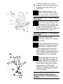
Slide the ACCESSORY TRAY (#8) (if so
equipped) over the user right seat back post
and down to make contact with the SEAT
HANDLEBAR.
Position the underside clamp bracket (A)
around the SEAT HANDLEBAR and tighten
the two clamp SCREWS and WASHERS(B).
NOTE: BE CAREFUL NOT TO OVER-TIGHTEN
THE SCREWS.
Align the four holes in the SEAT BACK (#5)
with those in the SEAT BACK POSTS. Insert
the four SCREWS (#1) and WASHERS (#2)
through the backside of the SEAT BACK
POSTS and into the SEAT BACK. Tighten the
four SCREWS with a hex key wrench.
NOTE: BE CAREFUL NOT TO OVER-TIGHTEN
THE SCREWS.
Unfold the two CONSOLE WIRE
HARNESSES (C) from the POST extending
from the FRAME.
Feed the two WIRE HARNESSES at the top
of the FRAME POST through the bottom of
the HANDLEBAR ASSEMBLY COLUMN.
Continue pushing the WIRE HARNESSES
until the CONNECTORS at the end of the
WIRE HARNESSES exit through the opening
at the top of the COLUMN. Gently pull the
WIRE HARNESSES to remove the slack.
Position the HANDLEBAR ASSEMBLY (#6)
so that the HANDLEBAR is facing the user
and slide the HANDLEBAR ASSEMBLY into
the FRAME POST (D), being careful not to
pinch the WIRES in the process. Align the
holes in the top of the HANDLEBAR
ASSEMBLY with those in the FRAME POST.
Install the two HANDLEBAR BOLTS (#3) to
secure it into position.
NOTE: BE VERY CAREFUL NOT TO DAMAGE
THE WIRES WHEN PASSING THE BOLTS
THROUGH THE HOLES. TIGHTEN THE BOLTS
SECURELY.

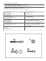
1 Seat Back Screw (4)
Vis pour dossier
Tornillo Posterior del Asiento
0017-00101-1131
2 Seat Back Washer (4)
Rondelle pour dossier
Arandela del Respaldo del Asiento
0017-00104-0253
3 Handlebar Bolt (2)
Boulon pour guidon
Perno del Manillar
0017-00101-1281
4 Console Screw (4)
Vis pour pupitre de commande
Tornillo de la Consola
5 Seat Back (1)
Dossier
Respaldo del Asiento
6 Handlebar Assembly (1)
Guidon
Montaje del Manillar
7 Display Console (1)
Pupitre d'affichage
Consola de Visualización
8 Accessory Tray Assembly (If so equipped) (1)
Bac pour accessoires (Si ainsi équipé )
Montaje de la Bandeja Accesoria (Si tan está equipado)
9 9V Battery (all models except 9500RHR) (1)
Batterie 9V (tous modèles sauf 9500RHR)
Pila de 9V (todos los modelos con excepción de 9500RHR)
0017-00003-0757
TOOLS REQUIRED FOR ASSEMBLY...
Phillips screwdriver, 3/16" hex key wrench, 5/32" hex key wrench
OUTILS NECESSAIRES POUR LE MONTAGE…
Tournevis cruciforme, clé mâle 3/16" (4,75 mm), clé mâle 5/32" (8,1 mm)
HERRAMIENTAS NECESARIAS PARA EL MONTAJE...
Destornillador Phillips, llave hexagonal de 3/16", llave hexagonal 5/32"

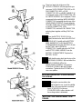
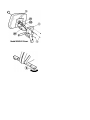
There is a large hole in the rear of the
DISPLAY CONSOLE (#7) through which you
can see a 10-PIN CONNECTOR (10P) or 16-
PIN CONNECTOR (16P), a 3-PIN
CONNECTOR (3P) on a WIRE HARNESS (if
so equipped), and a 4-PIN CONNECTOR (4P)
on a WIRE HARNESS (if so equipped). These
correspond to the matching WIRE HARNESS
CONNECTORS protruding from the top of the
HANDLEBAR ASSEMBLY. Properly align the
LOCKING TABS of the 10-PIN CONNECTOR
or 16-PIN CONNECTOR, 3-PIN
CONNECTOR, and the 4-PIN CONNECTOR
and plug them together until they SNAP into
place.
Remove the BATTERY DOOR (E) (if so
equipped) located on the back of the DISPLAY
CONSOLE (#7). Carefully pull the BATTERY
WIRE HARNESS (F) out of the BATTERY
COMPARTMENT. Plug the BATTERY (G) into
the BATTERY WIRE HARNESS
CONNECTOR. Carefully place the BATTERY
and BATTERY WIRE HARNESS into the
BATTERY COMPARTMENT. Replace the
BATTERY DOOR.
Carefully feed the wires back into the top of the
HANDLEBAR ASSEMBLY (#6) and attach the
DISPLAY CONSOLE (#7) to the
HANDLEBAR ASSEMBLY using the four
CONSOLE SCREWS (#4) and a Phillips
screwdriver. Tighten the four SCREWS in a
criss-cross pattern.
NOTE: BE CAREFUL NOT TO OVERTIGHTEN
THE SCREWS.
After placing the exercise bike in the
intended location for use, check the stability
of the bike. If the exercise bike is not level,
turn a LEVELER (E) in the rear
STABILIZER BAR in either direction until
the rocking motion is eliminated.
NOTE: ONLY ONE LEVELER NEEDS TO BE
TURNED.
7

7
-
 1
1
-
 2
2
-
 3
3
-
 4
4
-
 5
5
-
 6
6


Life Fitness 9500HR Manuel utilisateur
- Taper
- Manuel utilisateur
- Ce manuel convient également à
dans d''autres langues
- English: Life Fitness 9500HR User manual
- español: Life Fitness 9500HR Manual de usuario
Documents connexes
Autres documents
-
Horizon Fitness Horizon S3+ Le manuel du propriétaire
-
 Sunny Health & Fitness SF-B1423 Manuel utilisateur
-
AFG 7.3AU Le manuel du propriétaire
-
-
 Ultrasport F-BIKE 200B Manuel utilisateur
-
Matrix ICR50 Le manuel du propriétaire
-
Lifefitness SMARTconnect RF Module Manuel utilisateur

