Murray 1695539 Le manuel du propriétaire
- Catégorie
- Souffleuses à neige
- Taper
- Le manuel du propriétaire

Snowthrower
Chasse-.eige
_ode|
Mfg. No. Description
1695539 Dual Stage Snowthrower, 8.0 Torque Power, 24 Inch
1742237
Revision O0
Rev. Date 712008
TP 199=4955=O0=LW=R

1
1
5
14
21
21
15
19
1742237 2

CONTENTS
HAZARD SYMBOLS AND THEIR MEANINGS ............ 4
OPERATING SYMBOLS AND THEIR MEANINGS ......... 4
ASSEMBLY ........................................... 9
OPERATION .......................................... 9
MAINTENANCE CHART ............................... 11
MAINTENANCE ...................................... 11
TROUBLE SHOOTING CHART ......................... 15
LiMiTED WARRANTY .................................. 16
Figures(Example:Figure1)arelocatedontheinsidefront and back
pagesofthis manuallocatedbeforethepartslist.
Generalinformation
Thisinstructionbookiswrittenforapersonwithsomemechanicalability.
Likemostservicebooks,notallthestepsaredescribed.Stepsonhowto
loosenortightenfastenersarestepsanyonecanfollowwithsome
mechanicalability.Readandfollowtheseinstructionsbeforeyouusethe
unit.
Know your product:ifyou understandthe unitand howtheunit
operates,you willget the bestperformance.Asyou readthis manual,
comparethe illustrationsto the unit. Learnthe locationandthefunction of
the controls.Tohelppreventan accident,followthe operatinginstructions
andthe safety rules.Keepthis manualfor futurereference.
iMPORTANT:Many unitsarenot assembledandaresoldin cartons,itis
the responsibilityof the ownerto makesurethe assemblyinstructionsin
this manualare exactlyfollowed.Otherunits arepurchasedin an
assembledcondition.On assembledunits,it is the responsibilityofthe
ownerto makesurethe unitis correctly assembled.The ownermust
carefullycheckthe unitaccordingto the instructionsinthis manualbefore
itisfirst used.
Need Assistance?
ifyou needadditional informationon assembling,operating,orservicing
yourequipmentcontactyour localDealer.
,__ Thismanualcontainssafetyinformationto makeyou
awareofthe hazardsandrisksassociatedwithsnow
throwers,and howto avoid them.The snowthrowerisdesignedand
intendedforremovalof snow,and shouldnot beusedfor any other
purpose. Itis importantthat you readand understandthese
instructions,andanyoneoperatingthe equipmentread and
understandtheseinstructions.
,_WARNING
The engineexhaustfrom this productcontainschemicalsknownto
the StateofCaliforniato cause cancer,birthdefects,or other
reproductiveharm.
A signalword (DANGER,WARNING,or CAUTION)isusedwith thealert
symbolto indicatethe likelihoodand the potentialseverityof injury.In
addition, a hazardsymbol may be usedto representthe type of hazard.
,_ DANGERindicatesa hazardwhich, ifnot avoided,will result in
death orserious injury.
WARNINGindicatesa hazardwhich,if notavoided,couldresult
indeathorseriousinjury.
CAUTION indicatesa hazardwhich, ifnotavoided, mightresult
in minor or moderateinjury.
CAUTION,when used withoutthe alertsymbol,indicatesa
situationthat could resultin damage to the equipment.
Controls & EquipmentFeatures(see Figure 1)
TractionDrive Lever (1)- Selectthe forwardor reversedirectionof
travel.
CrankAssembly (2)- Changesthe directionof the dischargechute.
Chute Deflector(3)- Changesthe distancethe snowisthrown.
DischargeChute (4)- Changesthe directionthe snowis thrown.
Auger Drive Lever (5)- Startsand stopsthe auger(snow gatheringand
throwing) whichalso propelsthe snowthrower.
SpeedShift Lever (6) - Selects thespeedofthe snowthrower.
HeightAdjustSkid (7) =Adjuststhe ground clearanceof the auger
housing.
DriftCutters (18)= (ifequipped)Cutsapaththrough snowhigherthan
the auger housing.
ShearBolts (19) - To protectthe machine,specialshear boltsare
designedto breakis an objectbecomeslodgedinthe augerhousing.The
useof a harderboltwill destroythe protectionprovidedbythe shear bolt.
Engine Features
SafetyKey (8) = Must beinsertedtostartthe engine.
Primer Button(9)- injectsfuel directlyintothe carburetorforfast starts
incoldweather.
ElectricStart Button (10) - On electricstart models,usedto startthe
engine.
SwitchBox (11)- Onelectric startmodels,used to attacha 220volt
electricpowercord.
Recoil Starter Handle(12) - Useto manuallystartthe engine.
StopSwitch(13) - Useto stop the engine.
Choke Control (14) - Useto starta coldengine.
1742237 3

Hazard Symbols and their meanings
Thesesymbols areused on yourequipmentanddefined inyour operating
manual.Reviewand understandthe meanings.The use ofone of these
symbolscombinedwitha signalword will alertyou to potentialhazards
andhowto avoidthem.
Safety Alert - identifies safety information about
hazards that can result in personal injury.
Operator's Manual - Read and understand
before performing any activity or running
equipment.
Rotating auger
Fire
o
Rotating impeller __
Explosion
Toxic fumes
_$ Shock
Rotating gears
Hot Surface
,l_lll%l_Sm),
Thrown objects
Keep a safe distance
from the equipment.
Never reach into
rotating parts.
Shut off engine and
remove spark plug
connector before
performing maintenance
or repair work.
Operating Symbolsand their meanings
Thesesymbols areusedonyour equipmentand definedinyour operating
manual,it is importantthat you reviewand understandthe meanings.
Failureto understandthe symbolsmightresultinharmto you.
Oil _ Forward
=_ Fuel Neutral
Reverse
On Off
I_=_= Primerbu, b (_ ,gnitionOn
_\_ @ Ignition Off
Throttle
Ignition Key
! + I Chokeoff
Push to engage
I×l c.o.ooo
electric start
@
Stop
Electric
Start
Slow
Fast
Engage
O Traction
Engine
Start
Engine Run
Engine Off
_%_ Auger Collector
Auger Clutch
_ Drive Clutch
Engage
Disengage
Discharge Chute
LEFT RIGHT
Chute Deflector
UP
DOWN
1742237 4

• Neverattempt to clear auger of debris orclogged snow whileequipmentis
engaged or engine is running. Cloggedor blockedaugers storeenergy
andcan rotateunexpectedly, EVENWiTH ENGINE OFR
o Stop engine and remove keys when performing maintenance on
equipment.
• Never leave the equipment unattendedwhile engine is running. Always
disengage the augerand traction controls, stop engine,and remove keys.
• Keep children, pets, and others out of the areaduring operation.Children
are oftenattracted to theequipment. Be mindful of all persons present.
o Keep all looseclothing far away from front of snow throwerand auger.
Scarves, mittens,dangling drawstrings, looseclothes and pants can
quickly become caught in the rotatingdevice and dismemberment wilt
occur.Tie uplong hair and removejewelry.
• The snow thrower is intendedto removesnow only. Do notuse for
purposesother than whatis intended.
• Do notclear snowacrosstheface of slopes. Exerciseextreme cautionwhen
changingdirectionon slopes.Do not attemptto clear steepslopes.
• Do not usethe snow throweron surfaces above ground level suchas roofs
of residences,garages, porches or other suchstructures or buildings.
_DANGER
• Uncloggingthe discharge chute is a hazardousactivity. Clogged or
blocked augers storeenergy and can rotate unexpectedly,even with
engine off.
• Never place hands inor near discharge chute.
• With engine OFF,wait for alt movingparts to cease movement, thenwith a
stick, clearthe chute. Even with engine off, parts may rotateand
dismemberment can occur.
• Clogged snow can hide other obstructionsinthe chute andcause damage
tothe equipment,impeller orauger. Take precautionswhen restatingthe
equipmentafter snow removal.
,_DANGER
• Beaware of your environment while operating equipment. Runningover
items suchas gravel, doormats, newspapers,toys, and rockshidden
under snow,can all be thrownfrom chute or jam in the auger.
. Always be aware ofthe directionthe snow is beingthrown. Nearby
pedestrians, pets or property may beharmed by objects beingthrown.
• Familiarizeyourself with thearea you planto work. Mark off boundariesof
walkwaysand driveways to prevent propertydamage from thrown objects.
° Takecaution whensnow throwing in unfamiliar areas.Stay alert for hidden
hazards andtraffic.
• After strikinga foreign object,turn engineOFF,wait for movingparts to
cease movement,andcheck immediatelyfor damage. Ifdamaged, repair
before startingand operating snow thrower.
• With engineOFF,wait for movingparts to stop and always use a stick to
clear discharge chute.
• If unit vibratesabnormally,turn engine OFE Vibration is generally a
warning of trouble. Seean authorizeddealer if necessaryfor repairs.
. Startand run engine outdoors.
• Do notstart or run engine inenclosedarea, even if doors or
windowsare open.
1742237 5

,_WARNING
WHEN ADDING FUEL
• Turn engine OFF and let enginecool at least2 minutesbefore
removinggas cap.
• Fillfuel tank outdoors or inwell-ventilated area.
• Donot overfill fueltank.
• Keep gasolineaway from sparks, open flames, pilotlights, heat,and
other ignition sources.
• Check fuel lines, tank, cap, and fittings frequentlyfor cracks or leaks.
Replaceifnecessary.
WHEN STARTING ENGINE
• Makesure spark plug,muffler,fuel capand air cleanerare in place.
• Donot crank enginewith spark plug removed.
• iffuel spills,wait untilit evaporatesbefore startingengine.
• Ifengine floods, set choketo OPEN/RUNposition, place throttle in
FASTandcrank until enginestarts.
WHEN OPERATING EQUIPMENT
• Donot chokecarburetor to stopengine.
WHEN TRANSPORTING EQUIPMENT
• Transport withfuel tank EMPTY.
WHEN STORING GASOLINE OR EQUIPMENT WiTH FUEL INTANK
• Store away from furnaces,stoves, water beaters orother appliances
that have pilotlight or other ignition source because they can ignite
gasoline vapors.
1742237 6

RULES FOR SAFE OPERATION
WARNING: This machine is capable of amputating hands and feet and throwing objects. Read these safety
_ ules and follow them closely. Failure to obey these rules could result in loss of control of unit, severe
personal injury or death to you, or bystanders, or damage to property or equipment. The triangle _, in text
signifies important cautions or warnings which must be followed.
Safe Operation Practices for Snowthrowers
IMPORTANT: Safety standards require operator presence controls
to minimize the risk of injury, Your snowthrower is equipped with
such controls. Do not attempt to defeat the function of the operator
presence control under any circumstances.
Training
8. Let engine (motor) and snowthrower adjust to outdoor temperatures
before starting to clear snow.
9. Always wear safety glasses or eye shields during operation or while
performing an adjustment or repair to protect eyes from foreign objects
that may be thrown from the machine.
10. Never operate the snowthrower without proper guards, plates or other
safety protective devices in place.
1. Read, understand, and follow all instructions on the machine and in the
manuals before operating this unit. Be thoroughly familiar with the
controls and the proper use of the equipment. Know how to stop the unit
and disengage the controls quickly.
2. Never allow children to operate the equipment. Never allow adults to
operate the equipment without proper instruction.
3. Keep the area of operation clear of all persons, particularly small
children and pets.
4. Exercise caution to avoid slipping or falling especially when operating in
reverse.
Preparation
1. Thoroughly inspect the area where the equipment is to be used and
remove all doormats, sleds, boards, wires, and other foreign objects.
2. Disengage all clutches and shift into neutral before starting the engine
(motor).
3. Do not operate the equipment without wearing adequate winter outer
garments. Wear footwear that will improve footing on slippery surfaces.
Avoid loose fitting clothing that can get caught in moving parts.
4. Handle fuel with care; it is highly flammable.
a. Use an approved fuel container.
b. Never add fuel to a running engine or hot engine.
c. Fill fuel tank outdoors with extreme care. Never fill fuel tank
indoors. Replace fuel cap securely and wipe up spilled fuel.
d. Never fill containers inside a vehicle or on a truck or trailer bed with
a plastic liner. Always place containers on the ground, away from
your vehicle, before filling.
e. When practical, remove gas-powered equipment from the truck or
trailer and refuel it on the ground. If this is not possible, then refuel
such on a trailer with a portable container, rather than from a
gasoline dispenser nozzle.
f. Keep nozzle in contact with the rim of the fuel tank or container
opening at all times, until refueling is complete. Do not use a nozzle
lock-open device.
g. Replace gasoline cap securely and wipe up spilled fuel.
h. If fuel is spilled on clothing, change clothing immediately.
5. Use extension cords and receptacles as specified by the manufacturer
for all units with electric drive motors or electric starting motors.
6. Adjust the collector housing height to clear gravel or crushed rock
surfaces.
7. Never attempt to make any adjustments while the engine (motor) is
running (except when specifically recommended by manufacturer).
Operation
1. Do not put hands or feet near or under rotating parts. Keep clear of the
discharge opening at all times.
2. Exercise extreme caution when operating on or crossing gravel drives,
walks or roads. Stay alert for hidden hazards or traffic.
3. After striking a foreign object, stop the engine (motor), disconnect the cord
on electric motors, thoroughly inspect snowthrower for any damage, and
repair the damage before restarting and operating the snowthrower.
4. If the unit should start to vibrate abnormally, stop the engine (motor) and
check immediately for the cause. Vibration is generally a warning of
trouble.
5. Stop the engine (motor) whenever you leave the operating position,
before unclogging the collector/impeller housing or discharge chute and
when making any repairs, adjustments, or inspections.
6. When cleaning, repairing, or inspecting, make certain the
collector/impeller and all moving parts have stopped. Disconnect the
spark plug wire and keep the wire away from the spark plug to prevent
accidental starting.
7. Do not run the engine indoors, except when starting the engine and for
transporting the snowthrower in or out of the building. Open the outside
doors; exhaust fumes are dangerous (containing CARBON
MONOXIDE, an ODORLESS and DEADLY GAS).
8. Exercise extreme caution when operating on slopes. Do not attempt to
clear steep slopes.
9. Never operate the snowthrower without proper guards, plates, or other
safety protective devices in place and working.
10. Never direct the discharge toward people or areas where property
damage can occur. Keep children and others away.
11. Do not overload the machine capacity by attempting to clear snow at too
fast a rate.
12. Never operate the machine at high transport speeds on slippery
surfaces. Look behind and use care when operating in reverse.
13. Disengage power to the collector/impeller when snowthrower is
transported or not in use.
14. Use only attachments and accessories approved by the manufacturer of
the snowthrower (such as cabs, tire chains, etc.).
15. Never operate the snowthrower without good visibility or light. Always be
sure of your footing and keep a firm hold on the handles. Walk, never
run.
16. Never touch a hot engine or muffler.
17. Never operate the snowthrower near glass enclosures, automobiles,
window wells, drop-offs, and the like without proper adjustment of the
snow discharge angle.
1742237 7

18.Neverdirectdischargeatbystandersorallowanyoneinfrontoftheunit.
19.Neverleavearunningunitunattended.Alwaysdisengagetheaugerand
tractioncontrols,stopengine,andremovekeys.
20.Donotoperatetheunitwhileundertheinfluenceofalcoholordrugs.
21.Keepinmindtheoperatorisresponsibleforaccidentsoccurringtoother
peopleorproperty.
22.Dataindicatesthatoperators,age60yearsandabove,areinvolvedina
largepercentageofpowerequipment-relatedinjuries.Theseoperators
shouldevaluatetheirabilitytooperatetheunitsafelyenoughtoprotect
themselvesandothersfrominjury.
23.DONOTwearlongscarvesorlooseclothingthatcouldbecome
entangledinmovingparts.
24.Snowcanhideobstacles.Makesuretoremoveallobstaclesfromthe
areatobecleared.
Children
Tragic accidents can occur if the operator is not alert to the presence of
children. Children are often attracted to the unit and the operating activity.
Never assume that children will remain where you last saw them.
1. Keep children out of the area and under the watchful care of another
responsible adult.
2. Be alert and turn off if children enter the area.
3. Never allow children to operate the unit.
4. Use extra care when approaching blind corners, shrubs, trees, or other
objects that may obscure vision.
Clearing A Clogged Discharge Chute
Hand contact with the rotating impeller inside the discharge chute is the
most common cause of injury associated with snowthrowers. Never use
your hand to clean out the discharge chute.
To clear the chute:
1. SHUT OFF THE ENGINE.
2. Wait 10 seconds to be sure the impeller blades have stopped rotating.
3. Always use a clean out tool, not your hands.
Service, Maintenance And Storage
1. Check shear bolts (pins) and other bolts at frequent intervals for proper
tightness to be sure the equipment is in safe working condition.
2. Never store the machine with fuel in the tank inside a building where
ignition sources are present such as hot water and space heaters, or
clothes dryers. Allow the engine to cool before storing in any enclosure.
3. Always refer to operator's manual for important details if the
snowthrower is to be stored for an extended period.
4. Maintain or replace safety and instruction labels as necessary.
5. Run the machine a few minutes after throwing snow to prevent
freeze-up of the collector/impeller.
6. If fuel is spilled, do not attempt to start the engine but move the machine
away from the area of spillage and avoid creating any source of ignition
until fuel vapors have dissipated.
7. Always observe safe refueling and fuel handling practices when
refueling the unit after transportation or storage.
8. Always follow the engine's manual instructions for storage preparations
before storing the unit for both short and long term periods.
9. Always follow the engine manual instructions for proper start-up
procedures when returning the unit to service.
10.Keep nuts and bolts tight and keep equipment in good condition.
11. Never tamper with safety devices. Check their proper operation
regularly and make necessary repairs if they are not functioning
properly.
12. Components are subject to wear, damage, and deterioration. Frequently
check components and replace with manufacturer's recommended
parts, when necessary.
13. Check control operation frequently. Adjust and service as required.
14. Use only factory authorized replacement parts when making repairs.
15.Always comply with factory specifications on all settings and
adjustments.
16. Only authorized service locations should be utilized for major service
and repair requirements.
17. Never attempt to make major repairs on this unit unless you have been
properly trained. Improper service procedures can result in hazardous
operation, equipment damage and voiding of manufacturer's warranty.
Emissions
1. Engine exhaust from this product contains chemicals known, in certain
quantities, to cause cancer, birth defects, or reproductive harm.
2. If available, look for the relevant Emissions Durability Period and Air
Index information on the engine emissions label.
ignition System
1. This spark ignition system complies with Canadian ICES-002.
1742237 8

ASSEMBLY
Read and follow the assembly and adjustment
instructions for your snow thrower. All fasteners
are in the parts bag. Do not discard any parts or
material until the unit is assembled.
_ WARNING: Before doing any
assembly or maintenance to the
snow thrower, remove the wire
from the spark plug.
NOTE: In this instruction book, left and right
describe the location of a part from the
operator's position behind the unit.
NOTE: Torque is measured in foot pounds
(metric N.m). This measurement describes
how tight a nut or bolt must be. The torque is
measured with a torque wrench.
NOTE: Fasteners and loose parts are shown
at full size in Figure 2 on page 32.
NOTE: Illustrations are located on page 2
and on pages 33 through 38.
Tools Required
1
1
2
2
2
1
1
1
1
Knife
Pliers
1/2 inch open end wrenches
9/16 inch open end wrenches
3/4 inch open end wrenches
Measuring tape or ruler
Screwdriver
3/8 inch open end wrench
7/16 inch open end wrench
How To Remove The Snow Thrower
From The Carton
1. (Figure 3) The snow thrower is shown in the
shipping position.
2. Remove packing material from wheels,
handle, and auger housing.
3. Locate and remove the parts bag (some
models do not have a parts bag).
4. Cut open the end of the carton next to the
handle.
5. To roll the snowthrower off of the carton, pull
on the handle.
CAUTION: DO NOT back over cables.
6. Remove any packing material that remains
from handle and auger housing.
7. Cut orange plastic shipping ties that may
secure the control cables to the LOWER
HANDLE.
8. If the control cables have become
disconnected from the control levers, then
attach the cable to the levers (see Owner's
Manual for illustration of cable and lever).
How To Assemble The Handle And
Crank Assembly
1. (Figure 4) Loosen, but do not remove, the
fasteners (1) in the upper holes of the lower
handle.
2. Remove the fasteners and the crank
assembly eyebolt (11)from the lower holes
of the lower handle.
3. (Figure 1) Put the shift lever (8) into first
forward position.
4. (Figure 4) Raise the upper handle (2) to the
operating position.
NOTE: Make sure the cables are not
caught between the upper and lower
handle.
5. Install the fasteners and the crank assembly
eyebolt (11) that were removed in step 2.
DO NOT tighten until all fasteners are in
place.
6. (Figure 5) Attach the crank rod (15) to the
universal joint assembly (18) with the hair
pin (12).
7. (Figure 4) Tighten nut on eye bolt (11).
Make sure eye bolt (11) is properly aligned
and the crank (18) can freely rotate.
8. Tighten all handle fasteners.
How To Install The Knob(s) (Figure 6)
NOTE: If knob(s) are already installed, go to
the next selection.
1. Attach the knob (3) onto the speed shift
lever (2). On some models, the knob (3)
is attached. To lock in position, tighten the
hex jam nut (1) against the bottom of the
knob (3).
2. Make sure the speed shift lever (2)
functions correctly. Move the speed shift
lever (2) through all speeds.
How To Assemble The Chute Deflector
NOTE: The chute ring assembly (1) comes
installed on the unit from the factory (see
Figure 7).
1. Turn crank assembly (18, Figure 4) until
the arrow on outer ring (2, Figure 7) of
chute ring assembly points forward.
2. Place chute ring (3) onto outer ring (2)
so the slot in the chute ring aligns with
the arrow on the outer ring.
3. Install chute deflector (4) using four screws
(5) and nuts (8) in holes as shown. The chute
deflector must point forward for proper
installation.
4. Tighten screws snugly but be careful not to
over-tighten.
Check The Cables
1. (Figure 8) Check the traction drive cable
(1) and the auger drive cable (2). If the
bottom of the cables have become
disconnected, reinstall the cables.
2. (Figure 10) If the top of the cables (5) have
become disconnected from the drive
levers (6), attach the cables (5) to the "Z"
fitting (7).
How To Set The Skid Height (Figure 1)
The snow thrower is equipped with height
adjustable skids (7) mounted on the outside of
the auger housing (4). To adjust the height of
the skids, see "How To Adjust The Height Of
The Skids" in the Maintenance section.
How To Set The Length Of The Cables
The cables were adjusted at the factory and no
adjustments should be necessary. However,
after the handles are put in the operating
position, the cables can be too tight or too loose.
If an adjustment is necessary, see "How To
Check And Adjust The Cables" in the Service
And Adjustment section.
How To Assemble The Drift Cutter
(if equipped)
Drift cutters are used to cut a path through snow
deeper than the auger housing.
1. (Figure 11) Loosen the fasteners (2) that
secure the drift cutters (1) to the auger
housing.
2. Raise the drift cutters (1) to the desired
height.
3. Tighten the fasteners (2).
How To Prepare The Engine
NOTE: The engine was shipped from the
factory filled with oi!. Check the level of the
oil. Add oil as needed.
_ ARNING: Follow the engine
manufacturer's instructions for the
type of fuel and oil to use. Always
use a safety fuel container. Do not smoke
when adding gasoline to the engine. When
inside an enclosure, do not fill with
gasoline. Before you add fuel, stop the
engine. Let the engine cool for several
minutes.
Check the oil. See the engine manufacturer's
instructions for the type of fuel and oil to use.
Before you use the unit, read the information on
safety, operation, maintenance, and storage.
Important! Before You Start Operating
C] Check the fasteners. Make sure all
fasteners are tight.
17 On electric start models, the unit was
shipped with the starter cord plugged
into the engine. Before operating,
unplug the starter cord from the engine.
OPERATION
NOTE: Illustrations are located on page 2
and on pages 33 through 38.
CAUTION: Use only attachments and
accessories approved by the manufacturer
of the snow thrower (such as tire chains,
electric start kits, etc.).
Know Your Snow Thrower (Figure 1)
Read this Instruction Book and safety rules
before operation the snow thrower. Compare the
illustration with your snow thrower to familiarize
yourself with the location of various controls and
adjustments.
How To Control The Discharge Of
The Snow
_h ARNING: Never direct the
discharge of snow toward
bystanders.
_ ARNING: Always stop the engine
before unclogging the discharge
chute or the auger housing and
before leaving the snow thrower.
1. (Figure I) Turn the crank assembly (2) to
change the discharge direction of the snow.
2. (Figure 12) Loosen the wing knob (1) on
the chute deflector (2) and move the chute
deflector (2) to set the distance. Move the
chute deflector (2) UP for more distance,
DOWN for less distance. Then tighten the
wing knob (1).
1742237 9

HowTo Stop The Snow Thrower
(Figure 1)
1. To stop discharging snow, release the auger
drive lever (5).
2. To stop the wheels, release the traction
drive lever (1).
3. To stop the engine, move the stop switch
(13) to the OFF position.
CAUTION: To stop the engine, do not move
the choke control to CHOKE position.
Backfire or engine damage can occur.
How To Go Forward or Backward
(Figure 1)
1. To change the ground speed, first release the
traction drive lever (1) and then move the
speed shift lever (6) to the desired speed.
2. Ground speed is determined by snow
conditions. Select the speed by moving the
speed shift lever (6) into the appropriate
notch on the shift lever plate.
Speed 1,2 Wet, Heavy
Speed 3 Light
Speed 4 Very Light
Speed 5, 6 Transport only
3. To go forward, engage the traction drive
lever (1). Maintain a firm hold on the handle
as the snow thrower starts to move forward.
Guide the snow thrower by moving the
handle either left or right. Do not attempt to
push the snow thrower.
4. To go backward, release the tractor drive
lever (1).
5. Move the speed shift lever (6) into either
first or second reverse.
6. Engage the traction drive lever (1).
IMPORTANT: Do not move the speed shift
lever (6) while the traction drive lever (1) is
engaged.
How To Throw Snow (Figure 1)
1. Engage the auger drive lever (5).
2. To stop throwing snow, release the auger
drive lever (5).
WARNING: The operation of any
snow thrower can result in foreign
objects being thrown into the eyes,
which can result in severe eye damage.
Always wear safety glasses or eye shields
while operating the snow thrower. We
recommend standard safety glasses or use
a wide vision safety mask over your
glasses.
How To Use The Wheel Lockout Pin
(Figure 13)
1. The right hand wheel is secured to the axle
with a klick pin (1). This unit was shipped
with this klick pin (1) through the wheel hole
in the locked position (2).
2. For ease of maneuverability in light snow
conditions, change the klick pin (1) to an
unlocked position (3).
3. Disconnect the klick pin (1) from the wheel
locked position (2). Push the klick pin (1)
through the unlocked axle hole only. The unit
is now in the single wheel drive unlocked
position (3).
Before Starting The Engine
1. Before you service or start the engine,
familiarize yourself with the snow thrower. Be
sure you understand the function and
location of all controls.
2. Check the tension of the clutch cable before
starting the engine. See "How To Adjust The
Clutch Cable" in the Maintenance section of
this manual.
3. Make sure that all fasteners are tight.
4. Make sure the height adjust skids are
properly adjusted. See "How To Adjust The
Height Of The Skids" in the Maintenance
section of this manual.
5. Check the air pressure in the tires. The
correct air pressure is 14 PSI (1 BAR) to 17
PSI (1.25 BAR). Do not exceed the
maximum amount of air pressure shown on
the side of the tire.
How To Stop The Engine (Figure 1)
1. Push the stop switch (13) to the OFF
position.
2. Pull out the safety key (8).
CAUTION: To stop the engine, do not move
the choke control to CHOKE position.
Backfire or engine damage can occur.
How To Start The Engine (Figure 1)
Models equipped with an Electric Starter
NOTE: An electric starter kit can be added to
recoil start engines. Electric starter kits are
available from your nearest authorized
service center.
_ ARNING: The starter is equipped
with a three-wire power cord and
plug and is designed to operate on
A.C. household current. The power cord
must be properly grounded at all times to
avoid the possibility of electrical shock
which can injure the operator. Carefully
follow all instructions in the "How To Start
The Engine" section. Make sure that your
house wiring is a three=wire grounded
system. If you are not sure, ask a licensed
electrician. If your house wire system is not
a three-wire grounded system, do not use
this electric starter under any conditions. If
your system is grounded but a three=hole
grounded receptacle is not available to start
the engine, have a three-hole grounded
receptacle installed by a licensed
electrician. To connect an A.C. power cord,
always connect the power cord to the
switch box (11) on the engine first. Then,
plug the other end into the three-hole
grounded receptacle. When disconnecting
the power cord, always unplug the end from
the three-hole grounded receptacle first.
How To Start A Cold Engine (Figure I)
1. Check the engine oil.
2. Fill the fuel tank with regular unleaded petrol.
See "How To Prepare The Engine".
3. Make sure the traction drive lever (1) and
the auger drive lever (5) are in the
disengaged (released) position.
4. Push the stop switch (13) to the ON
position.
5. Push in the safety key (8).
6. Rotate the choke knob (14) to the CHOKE
position.
7. (Electric Start) Connect the power cord to
the starter motor located on the engine.
8. (Electric Start) Plug the other end of the
power cord into a three-hole, grounded
A.C. receptacle. (See the WARNING in
this section).
9. Push the primer button (9). Every time you
push the primer button (9), wait two
seconds. For the number of times required to
push the primer button (9), see the engine
manufacturer's instructions.
10. (Electric Start) Push on the electric start
button (10) until the engine starts. Do not
crank for more than 5 seconds at a time.
Wait one minute between starts to allow the
starter to cool.
11. (Recoil Start) Slowly pull the recoil starter
handle (12) until resistance is felt and then
pull rapidly to start the engine. Do not allow
the recoil starter handle (12) to snap back.
Slowly return the recoil starter handle (12).
12.1f the engine does not start in 5 or 6 tries,
See the "Trouble Shooting Chart"
Instructions.
13.Allow the engine to warm up for several
minutes. As the engine warms up, adjust the
choke knob (14) toward the RUN position.
Wait until the engine runs smoothly before
each choke adjustment.
14.(Electric Start) First disconnect the power
cord from the three-hole receptacle. Then,
disconnect the power cord from the starter
motor.
NOTE: In temperatures below 0°F (-18°C),
allow the engine to warm up for several
minutes before blowing snow.
_L ARNING: Never run the engine
indoors or in enclosed, poorly
ventilated areas. Engine exhaust
contains carbon monoxide, an odorless
and deadly gas. Keep hands, feet, hair and
loose clothing away from any moving parts
located on the engine or the snow thrower.
The temperature of muffler and nearby
areas may exceed 150°F (66°C). Avoid
these areas.
How To Start A Warm Engine (Figure I)
If an engine has been running and is still warm,
leave the choke control (14) in the off position
and do not push the primer button (9). If the
engine fails to start, follow the instructions "How
To Start A Cold Engine".
NOTE: Do not use the primer button (9) to
start a warm engine.
How To Start An Engine With A Frozen Electric
Starter (Figure I)
If the electric starter is frozen and will not turn
the engine, follow the instructions below.
1. Pull as much starter rope as possible out of
the starter.
2. Release the starter handle and let it snap
back against the starter. Repeat until the
engine starts.
1742237 10

Warmengineswillcausecondensationincold
weather.Topreventpossiblefreeze-upofrecoil
starterandenginecontrols,proceedasfollows
aftereachsnowremovaljob.
1.Runthesnowthrowerafewminutesafter
throwingsnowtopreventfreeze-upofthe
auger/impeller.
2.Withengineoff,allowenginetocoolfor
severalminutes.
3.Pullstarterropeveryslowlyuntilresistance
isfelt,thenstop.Allowthestarterropeto
recoil.Repeatthreetimes.
4.Withtheenginenotrunning,wipeallsnow
andmoisturefromthecarburetorcoverin
areaofcontrolsandlevers.Also,movethe
chokecontrolandstarterhandleseveral
times.
HowToRemoveSnowor Debris From
The Auger Housing
_ ARNING: Do not attempt to
remove snow or debris that may
become lodged in auger housing
with your hands. Use the clean-out tool or
a pry bar to remove snow or debris.
(Figure 21) On some models, a clean=out tool
(1) is attached to the top of the auger housing.
Use the clean-out tool (1) to remove snow
from the auger housing.
1. (Figure I) Release the auger drive lever
(5)
2. Pull out the safety key (8).
3. Do not place your hands in the auger
housing (4) or the discharge chute (3).
4. (Figure 21) Use the clean-out tool (1) or a
pry bar to remove any snow or debris.
Snow Throwing Tips
1. For maximum snow thrower efficiency in
removing snow, adjust ground speed. Go
slower in deep, freezing or wet snow. If the
wheels slips, reduce forward speed.
2. Most efficient snow throwing is accomplished
when the snow is removed immediately after
if falls.
CAUTION: DO not overload the machine
capacity by attempting to clear snow at
too fast a rate.
3. For complete snow removal, slightly overlap
each previous path.
4. Whenever possible, discharge the snow
down wind.
5. For normal usage, set the skids so that the
scraper bar is 1/8" (3 mm) above the skids.
For extremely hard-packed snow surfaces,
adjust the skids upward so that the scraper
bar touches the ground.
6. Rocks and gravel must not be picked up and
thrown by the machine. On gravel or crushed
rock surfaces, set the skids at 1-1/4 inch
(32 mm) below the scraper bar. See "How To
Adjust The Height Of The Skids" in the
Maintenance section.
7. After each snow throwing job, allow the
engine to idle for a few minutes. The snow
and accumulated ice will melt off the engine.
8. Clean the snow thrower after each use.
9. Remove ice, snow and debris from the entire
snow thrower. Flush with water to remove all
salt or other chemicals. Wipe snow thrower
dry.
MAINTENANCE CHART
CUSTOMER RESPONSIBILITIES
SERVICE RECORDS Before Every Every Every
Fill in dates as you complete Each First 2 5 10 25 Each Before
regular service. Use Hours Hours Hours Hours Season Storage
SERVICE DATES
Change Engine Oil
Check And Tigh{en Ail screws and Nuts
Check Spark Plug
Check Fuel
Check Auger Clutch Cable Adjustment
(See Cable Adjustment)
Lubricate All Pivot Points
Lubricate Drive Chains and Sprockets
MAINTENANCE
NOTE: illustrations are located on page 2
and on pages 33 through 38.
Use the following maintenance section to keep
your unit in good operating condition. All the
maintenance information for the engine is in the
engine manufacturer's instructions. Before you
start the engine, read this book.
_ ARNING: Before you make an
inspection, adjustment (except
carburetor), or repair, disconnect
the wire from the spark plug.
General Recommendations
The warranty on this snow thrower does not
cover items that have been subjected to
operator abuse or negligence. To receive full
value from the warranty, the operator must
maintain the snow thrower as instructed in this
manual.
Some adjustments must be made periodically to
properly maintain the snow thrower.
After Each Use
[] Check for any loose or damaged parts.
[] Tighten any loose fasteners.
,/
[] Check and maintain the auger.
[] Check controls to make sure they are
functioning properly.
[] If any parts are worn or damaged, replace
immediately.
[] Check all safety and instruction decals and
labels. Replace any decals or labels that are
missing or cannot be clearly read.
All adjustments in the Maintenance section of
this manual should be checked at least once
each season.
1742237 11

As Required
The following adjustment should be preformed
more than once each season.
1. Adjust the auger drive belt after the first 2 to
4 hours, again at mid-season, and twice
each season thereafter. See "How To Adjust
The Auger Drive Belt" in the Maintenance
section.
Lubrication
Every 10 Hours (Figure 14)
1. Lubricate the Zerk fittings (1) every ten
hours with a grease gun.
2. Each time a shear bolt is replaced, the auger
shaft must also be greased.
3. Lubricate all pivot points.
Every 25 Hours
Chute Rotation Gear
(Figure 5) Lubricate the chute rotation gear (1)
with automotive type oil.
Chains
1. (Figure I) Move the speed shift lever (6) to
first gear.
2. Remove the gas from the gas tank. Stand
the snow thrower up on the front end of the
auger housing (4).
WARNING: Drain the gasoline
outdoors, away from fire or flame.
3. (Figure 23) Loosen the bolts (3) on each
side of the bottom panel (2).
4. Remove the bottom panel (2).
5. (Figure 15) Lubricate the chains (5) with a
chain type lubricant.
6. Wipe the he×shaft and sprockets (6) with
5W30 motor oil.
NOTE: If grease or oil come in contact
with the disc drive plate (1) or the friction
wheel (3), damage can result. Clean off
any oil or grease with a alcohol base
solvent.
7. (Figure 23) Install the bottom panel (2).
8. Tighten the bolts (3) on each side of the
bottom panel (2).
Items Not To Lubricate (Figure 15)
1. Do not lubricate the he× shaft and
sprockets (6). All bearings and bushings are
lifetime lubricated. For storage, put a slight
amount of 5W-30 motor oil on a cloth and
wipe the he× shaft and sprockets (6) to
prevent rust.
2. If grease or oil comes in contact with the
disc drive plate (1) or the friction wheel
(3), the friction wheel (3) can be damaged.
Make sure to thoroughly clean the disc drive
plate (1) and the friction wheel (3).
CAUTION: Any greasing or oiling of the
above components can cause
contamination of the friction wheel (3). If
the disc drive plate (1) or the friction
wheel (3) become contaminated with
grease or oil, damage to the friction wheel
will result.
The auger gear case is lubricated at the
factory and does not require additional
lubrication. If for some reason the lubricant
leaks out, have the auger gear case checked
by a factory authorized service center.
How To Adjust The Height Of The Skids
(Figure 1)
This snow thrower is equipped with two height
adjustable skids (7). These skids elevate the
front of the snow thrower. For normal hard
surfaces, such as a paved driveway or walk,
adjust the skids as follows.
1. Put the snow thrower on a level surface.
2. Make sure both tires are equally inflated. The
correct air pressure is 14 PSI (1 BAR) to 17
PSI (1.25 BAR). Do not exceed the
maximum amount of air pressure shown on
the side of the tire.
3. Put the extra shear bolts (found in the parts
bag) under each end of the scraper bar (15)
next to the adjustable skids (7).
4. Loosen the mounting nuts (16) that hold the
adjustable skids (7). To bring the front of the
snow thrower down, raise each adjustable
skids (7). Tighten the mounting nuts (16).
NOTE: For rocky or uneven surfaces, raise
the front of the snow thrower by moving the
adjustable skids (7) down.
WARNING: Be certain to maintain
proper ground clearance for the
area to be cleared. Objects such as
gravel, rocks or other debris, if struck by
the impeller, can be thrown with sufficient
force to cause personal injury, property
damage or damage to the snow thrower.
How To Adjust The Scraper Bar
(Figure 1)
After considerable use, the scraper bar (15) will
become worn. The scraper bar (15), in
conjunction with the skids, must be adjusted to
allow 1/8 inch clearance between the scraper
bar (15) and the sidewalk or area to be cleared.
1. Put the snow thrower on a level surface.
2. Make sure both tires are equally inflated. The
correct air pressure is 14 PSI (1 BAR) to 17
PSI (1.25 BAR). Do not exceed the
maximum amount of air pressure shown on
the side of the tire.
3. Loosen the carriage bolts and nuts that
hold the scraper bar (15) to the auger
housing (4).
4. Adjust the scraper bar (15) to allow 1/8 inch
clearance between the scraper bar (15) and
the sidewalk or area to be cleared.
5. Tighten the carriage bolts and nuts. Make
sure that the scraper bar (15) is parallel with
the sidewalk or area to be cleared.
6. To extended the life of the scraper bar (15),
remove and reverse the mounting of the
scraper bar (15).
How To Check And Adjust The Cables
The traction drive cable and the auger drive
cable are adjusted at the factory. During normal
use, a cable can become stretched and must be
checked and adjusted as follows.
How To Check The Cables (Figure 16)
1. To check for correct adjustment, disconnect
the "Z" fitting (1) from the drive lever (2).
2. Move the drive lever (2) forward until the
drive lever (2) is contacting the plastic
bumper (3).
3. The control cable is correctly adjusted if the
center of the "Z" fitting (1) is aligned (4)
with the hole in the drive lever (2) and there
in no droop in the cable.
How To Adjust The Auger Drive Cable
1. Remove the gas from the gas tank. Stand
the snow thrower up on the front end of the
auger housing.
_ WARNING: Drain the gasoline
outdoors, away from fire or flame.
2. (Figure 16) Disconnect the "Z" fitting (1)
from the drive lever (2).
3. (Figure 17) Pull the spring cover up to
expose the spring (5). Push the cable (6)
through the spring (5) to expose the square
end (7) on the cable (6).
4. Hold the square end (7) with pliers and
adjust the Iocknut (8) in or out until the
excess slack is removed.
5. Pull the cable (6) back through the spring
(5).
6. (Figure 16) Connect the "Z" fitting (1) to the
drive lever (2).
NOTE: When the auger drive belt is adjusted
or replaced, check and adjust the cable.
How To Adjust The Traction Drive Cable
1. Remove the gas from the gas tank. Stand
the snow thrower up on the front end of the
auger housing.
WARNING: Drain the gasoline
outdoors, away from fire or flame.
2. (Figure 23) Loosen the bolts (3) on each
side of the bottom panel (2).
3. Remove the bottom panel (2).
4. (Figure 16) Disconnect the "Z" fitting (1)
from the traction drive lever (2).
5. (Figure 28) Slide the cable boot (3) off the
cable adjustment bracket (4).
6. Push the bottom of the traction control
cable (5) through the cable adjustment
bracket (4) until the "Z" hook (6) can be
removed.
7. Remove the "Z" hook (6) from the cable
adjustment bracket (4). Move the "Z" hook
(6) down to the next adjustment hole.
8. Pull the traction control cable (5) up
through the cable adjustment bracket (4).
9. Put the cable boot (3) over the cable
adjustment bracket (4).
lO.(Figure 16) install the "Z" fitting (1) to the
traction drive lever (2).
1742237 12

11.(Figure 15) To check the adjustment,
depress the drive lever and check the length
"A" of the drive spring (7). In correct
adjustment, the length "A" of the drive
spring (7) is as follows:
minimum 3 inches (76 mm)
maximum 3-3/8 inches (85 mm).
12.(Figure 23) Install the bottom panel (2).
13.Tighten the bolts (3) on each side of the
bottom panel (2).
How To Adjust The Belts
The belts will stretch during normal use. If you
need to adjust the belts due to wear or stretch,
proceed as follows.
How To Adjust The Auger Drive Belt
If the snow thrower will not discharge snow,
check the adjustment of the auger drive cable.
See "How To Check And Adjust The Cables" in
the Maintenance section. If the adjustment is
correct, then check the condition of the auger
drive belt. If the auger drive belt is damaged,
replace the auger drive belt. See "How To
Replace The Belts" in the Maintenance section.
If the auger drive belt is loose, adjust as follows.
1. Disconnect the spark plug wire.
2. (Figure 18) Remove screw (2) from belt
cover (1). Remove the belt cover (1).
3. (Figure 19) Loosen the nut (2) on the idler
pulley (3) Move the idler pulley (3) 1/8 inch
(3 mm) toward the auger drive belt (4).
4. Tighten the nut (2).
5. (Figure 22) Depress the auger drive lever.
Check the tension on the auger drive belt
(4). In correct adjustment, the auger drive
belt (4) will deflect 1/2 inch (12.5 ram) (5)
with moderate pressure. If the adjustment is
not correct, repeat the adjustment.
6. (Figure 18) Install the belt cover (1). Tighten
screw (2).
7. Check the adjustment of the auger drive
cable. See "How To Check And Adjust The
Cables" in the Maintenance section.
8. Attach the spark plug wire.
Traction Drive Belt
The traction drive belt has constant spring
pressure and does not require an adjustment. If
the traction drive belt is slipping, replace the
belt. See "How To Replace The Belts" in the
Maintenance section.
How To Replace The Belts
The drive belts are of special construction and
must be replaced with original factory
replacement belts available from your nearest
authorized service center.
Some steps require the assistance of a second
person.
How To Remove the Auger Drive Belt
If the auger drive belt is damaged, the snow
thrower will not discharge snow. Replace the
damaged belt as follows.
1. Disconnect the spark plug wire.
2. (Figure 23) Loosen the bolts (3) on each
side of the bottom panel (2).
3. Remove the bottom panel (2).
4. (Figure 18) Remove screw (2) from belt
cover (1). Remove the belt cover (1).
5. (Figure 19) Loosen the belt guide (9). Pull
the belt guide (9) away from the auger
drive pulley (10).
6. Pull the idler pulley (3) away from the auger
drive belt (4) and slip the auger drive belt
(4) offof the idler pulley (3).
7. Remove the auger drive belt (4) from the
engine pulley (11). To remove the auger
drive belt (4), the engine pulley (11) may
have to be partially rotated.
8. (Figure 20) Remove the top four bolts (21)
that hold together the auger housing (22)
and the motor box (23). Loosen the bottom
two bolts (24). The auger housing (22) and
the motor box (23) can now be split apart for
removal of the belt.
9. (Figure 19) Remove the old auger drive
belt (4) from the auger drive pulley (10).
Replace the auger drive belt (4) with an
original factory replacement belt available
from an authorized service center.
10. Install the new auger drive belt (4) onto the
auger drive pulley (10).
11. Assemble the auger housing (22) to the
motor box (23) with the four bolts (21) that
were removed in step 8. Tighten the bottom
two bolts (24).
12. Install the auger drive belt (4) onto the
engine pulley (11).
13.Slip the auger drive belt (4) under the idler
pulley (3).
14.Adjust the auger drive belt (4). See "How To
Adjust The Auger Drive Belt" in the
Maintenance section.
15.Adjust the belt guide (9). See "How To
Adjust The Belt Guide" in the Maintenance
section.
16.(Figure 18) Install the belt cover (1). Tighten
screw (2).
17. Check the adjustment of the cables. See
"How To Check And Adjust The Cables" in
the Maintenance section.
18. Connect the spark plug wire.
How To Remove the Traction Drive Belt
If the snow thrower will not move forward, check
the traction drive belt for wear or damage. If the
traction drive belt is worn or damaged, replace
the belt as follows.
1. Disconnect the spark plug wire.
2. Remove the auger drive belt. See "How To
Remove The Auger Drive Belt" in the
Maintenance section.
3. (Figure 19) Remove the e-ring (17) from
one end of the swing plate axle rod (18).
Remove the swing plate axle rod (18) to
allow the the swing plate to pivot forward.
4. Remove the traction drive spring (16).
5. Remove the old traction drive belt (13) from
the traction drive pulley (14) and from the
engine pulley (15). Replace the traction
drive belt (13) with an original factory
replacement belt available from an
authorized service center.
6. Install the new traction drive belt (13) onto
the traction drive pulley (14) and onto
engine pulley (15).
7. Make sure the traction drive idler pulley
(12) is properly aligned with the traction
drive belt (13).
8. Attach the traction drive spring (16).
9. Install the swing plate axle rod (18) and
secure with the e-ring (17) removed earlier.
10. (Figure 31) The bottom of the swing plate
(20) must be positioned between the
alignment tabs (19). Make sure the swing
plate (20) is properly secured.
NOTE: If the drive will not engage after
the traction drive belt has been replaced,
then check to make sure that the swing
plate is positioned between the alignment
tabs (19).
11. (Figure 19) Install and adjust the auger
drive belt (4). See "How To Remove The
Auger Drive Belt" in the Maintenance section.
12.Adjust the belt guide (9). See "How To
Adjust The Belt Guide" in the Maintenance
section.
13. (Figure 23) Install the bottom panel (2).
14.Tighten the bolts (3) on each side of the
bottom panel (2).
15. (Figure 18) Install the belt cover (1). Tighten
screw (2).
16. Check the adjustment of the cables. See
"How To Check And Adjust The Cables" in
the Maintenance section.
17. Connect the spark plug wire.
How To Adjust The Belt Guide
1. Disconnect spark plug wire.
2. (Figure 18) Remove screw (2). Remove the
belt cover (1).
3. (Figure 1) Engage the auger drive lever (5).
4. (Figure 24) Measure the distance between
the belt guide (2) and auger drive belt (3).
The correct distance (4) is 1/8 inch (3 mm).
5. If an adjustment is necessary, loosen the
mounting bolt for the belt guide (2). Move
the belt guide (2) to the correct position
(4). Tighten the mounting bolt for the belt
guide (2).
6. (Figure 18) Install the belt cover (1). Tighten
screw (2).
7. Connect the spark plug wire.
How To Adjust Or Replace The Friction
Wheel
How To Check The Friction Wheel
If the snow thrower will not move forward, check
the traction drive belt, the traction drive cable or
the friction wheel. If the friction wheel is worn or
damaged, it must be replaced. See "How To
Replace the Friction Wheel" in this section. If the
friction wheel is not worn or damaged, check as
follows.
1. (Figure I) Remove the gas from the gas
tank. Stand the snow thrower up on the front
end of the auger housing (4).
WARNING: Drain the gasoline
outdoors, away from fire or flame.
2. Disconnect the spark plug wire.
3. (Figure 23) Loosen the bolts (3) on each
side of the bottom panel (2).
4. Remove the bottom panel (2).
5. (Figure 1) Position the shift speed lever (6)
in the lowest forward speed.
1742237 13

6.(Figure 25) Note the position of the friction
wheel (4). The correct distance "A" from the
right side of the friction wheel (4) to the
outside of the motorbox is as follows:
Tire Size Distance "A"
12 and 13 inch 4-1/8" (10.5 cm)
16 inch 4-5/16" (10.95 cm)
If the friction wheel (4) is not in the correct
position, adjust as follows.
How To Adjust The Friction Wheel
1. (Figure 1) Position the shift speed lever (6)
in the lowest forward speed.
2. (Figure 9) Loosen the bolts (1) on the
speed control rod (8).
3. (Figure 25) Move the friction wheel (4) to
the correct position.
4. (Figure 9) Tighten the bolts (1) on the
speed control rod (8).
5. (Figure 23) Install the bottom panel (2).
6. Tighten the bolts (3) on each side of the
bottom panel (2).
How To Replace The Friction Wheel
If the friction wheel is worn or damaged, the
snow thrower will not move forward. The friction
wheel must be replaced as follows.
1. (Figure 1) Remove the gas from the gas
tank. Stand the snow thrower up on the front
end of the auger housing (4).
WARNING: Drain the gasoline
outdoors, away from fire or flame.
2. Disconnect the spark plug wire.
3. (Figure 29) Remove the fasteners that
secure the left wheel (10). Remove the left
wheel (10) from the axle (11).
4. Loosen the bolts (3) on each side of the
bottom panel (2).
5. Remove the bottom panel (2).
6. (Figure 30) Remove the fasteners that
secure the drive sprocket (12) to the axle
(11).
7. Remove the right wheel, axle (11), and drive
sprocket (12).
8. (Figure 31) Remove the four bolts (16) that
hold the bearings (7) on each side of the
hex shaft (8).
9. (Figure 32) Remove the hex shaft (8) and
bearings (7).
NOTE: Take special note of the position of
the washers (17).
10. (Figure 27) Remove the three fasteners (4)
that hold the friction wheel (5) to the hub
(6).
11. (Figure 27) Remove the friction wheel (5)
from the hub (6). Slip the friction wheel (5)
off the hex shaft (8).
12.Assemble the new friction wheel (5) onto
hub (6) with the fasteners removed earlier.
13.(Figure 32) Install the hex shaft (8) and
bearings (7) with the four bolts removed
earlier.
Make sure the washers (17) are properly
installed in the original position. Also,
make sure the two washers (13) are
properly aligned with the actuator arms
(14).
14. Make sure the hex shaft (8) turns freely.
15.(Figure 30) install the right wheel, axle (11),
and drive sprocket (12) with the fasteners
removed earlier. Install the chain (15) onto
the drive sprocket (12).
16. Check the adjustment of the friction wheel.
See "How To Adjust The Friction Wheel" in
this section.
17. Make sure the fdction wheel and the disc
drive plate are free from grease or oil.
18.(Figure 23) Install the bottom panel (2).
19.Tighten the bolts (3)on each side of the
bottom panel (2).
20. Install the left wheel (10) to the axle (11)
with the fasteners removed earlier.
21. Connect the spark plug wire.
How To Replace the Auger Shear Bolt
The augers are secured to the auger shaft with
special shear bolts. These shear bolts are
designed to break and protect the machine if an
object becomes lodged in the auger housing. Do
not use a harder bolt as the protection provided
by the shear bolt will be lost.
,_ WARNING: For safety and to
protect the machine, use only
original equipment shear bolts.
To replace a broken shear bolt, proceed as
follows. Extra shear bolts were provided in the
assembly parts bag.
1. (Figure 1) Move the stop switch (13) to the
stop position. Disengage all controls.
2. Disconnect the spark plug wire. Make sure
all moving parts have stopped.
3. (Figure 14) Lubricate the auger shaft Zerk
fitting (1), if equipped, with a grease gun.
4. (Figure 26) Align the hole in the auger with
the hole in the auger shaft. Install the new
shear bolt (2), spacer (3), and Iocknut (4).
5. Connect the spark plug wire.
How To Prepare The Snow Thrower For
Storage
_ ARNING: Do not remove gasoline
while inside a building, near a fire,
or while you smoke. Gasoline
fumes can cause an explosion or a fire.
If the snow thrower is to be stored for an
extended period, refer to the engine
manufacturer's operating manual (included with
some models) for important maintenance or
storage details.
1. Drain the fuel tank.
2. Let the engine run until it is out of gasoline.
3. Never store the snow thrower with fuel in the
tank inside a building where ignition sources
are present such as hot water and space
heaters, clothes dryers, and the like. Allow the
engine (motor) to cool before storing in any
enclosure.
4. Drain the oil from the warm engine. Fill the
engine crankcase with new oil.
5. Thoroughly clean the snow thrower.
6. Lubricate all lubrication points. See the
Maintenance section.
7. Be sure that all nuts, bolts and screws are
securely fastened. Inspect all visible moving
parts for damage, breakage and wear.
Replace if necessary.
8. Cover the bare metal parts of the blower
housing, auger, and the impeller with spray
rust preventative lubricant.
9. Put the unit in a building that has good
ventilation. Store in a clean and dry area, but
NOT near a stove, furnace or water heater
which uses a pilot light or any device that can
create a spark.
10. If the machine must be stored outdoors,
block up the snow thrower to be sure the
entire machine is off the ground.
11 .Cover the snow thrower with a suitable
protective cover that does not retain
moisture. Do not use plastic.
How To Order Replacement Parts
The replacement parts are shown either on the
back pages of this Instruction Book or in a
separate Parts List Book.
Use only manufacturer's authorized or approved
replacement parts. Do not use attachments or
accessories not specifically recommended for
this unit. In order to obtain proper replacement
parts you must supply the model number (see
nameplate).
To obtain replacement parts, contact your local
Dealer.
Replacement parts for the engine, transaxle, or
transmission, are available from the
manufacturer's authorized service centre found
in the yellow pages of the telephone directory.
Also, see the individual engine or transmission
warranties to order replacement parts.
When ordering the following information is
required:
(1) The Model Number
(2) Serial Number
(3) Part Number
(4) Quantity
1742237 14

TROUBLE SHOOTING CHART
TROUBLE CAUSE CORRECTION
Difficult starting Defective spark plug. Replace spark plug.
Water or dirt in fuel system.
Engine runs erratic Blocked fuel line, empty gas tank, or stale
gasoline.
Engine stalls Unit running on CHOKE.
Engine runs erratic; Water or dirt in fuel system.
Loss of power
Excessive vibration Loose parts: damaged impeller.
Unit fails to propel itself
Unit fails to discharge snow
Drive belt loose or damaged.
Incorrect adjustment of traction drive cable.
Worn or damaged friction wheel.
Auger drive belt loose or damaged.
Auger control cable not adjusted correctly.
Shear bolt broken.
Discharge chute clogged.
Foreign object lodged in auger.
Use carburetor bowl drain to flush and refill with
fresh fuel.
Clean fuel line; check fuel supply; add fresh
gasoline.
Set choke lever to RUN position.
Use carburetor bowl drain to flush and refill with
fresh fuel.
Stop engine immediately and disconnect spark
plug wire. Tighten all bolts and make all
necessary repairs. If vibration continues, have
the unit serviced by a competent repairman.
Replace drive belt.
Adjust traction drive cable.
Replace friction wheel.
Adjust auger drive belt; replace if damaged.
Adjust auger control cable.
Replace shear bolt.
Stop engine immediately and disconnect spark
plug wire. Clean discharge chute and inside of
auger housing.
Stop engine immediately and disconnect spark
plug wire. Remove object from auger.
1742237 15

BRIGGS AND STRATTON POWER PRODUCTS GROUP, L.L.C. OWNER WARRANTY POLICY
EffectiveJanuary 1,2008 replaces all undatedWarrantiesand allWarrantiesdated beforeJanuary 1,2008
UMITED WARRANTY
Briggs & Stratton Power Products Group, LLC will repair or replace, free of charge, any part(s) of the product that is defective in material or workmanship or
both. Transportation charges on product submitted for repair or replacement under this warranty must be borne by purchaser. This warranty is effective for
the time periods and subject to the conditions stated below. For warranty service, find the nearest Authorized Service Dealer in our dealer Iocator map at
www.murray,com
THERE IS NO OTHER EXPRESS WARRANTY, IMPLIED WARRANTIES, INCLUDING THOSE OF MERCHANTABILITY AND FITNESS FOR A PARTICU-
LAR PURPOSE, ARE LIMITED TO ONE YEAR FROM PURCHASE, OR TO THE EXTENT PERMITTED BY LAW. ANY AND ALL IMPLIED WARRANTIES
ARE EXCLUDED. LIABILITY FOR INCIDENTAL OR CONSEQUENTIAL DAMAGES ARE EXCLUDED TO THE EXTENT EXCLUSION IS PERMITTED BY
LAW. Some states or countries do not allow limitations on how long an implied warranty lasts, and some states or countries do not allow the exclusion or
limitation of incidental or consequential damages, so the above limitation and exclusion may not apply to you. This warranty gives you specific legal rights
and you may also have other rights which vary from state to state or country to country.
WARRANTY TERMS
Consumer Commercial
Brand / Unit Use Use
Dual Stage Snowthrower ........................... 2years ........................ 90 Days
The warranty period begins on the date of purchase by the first retail consumer or commercial end user, and continues for the period of time stated above.
"Consumer use" means personal residential household use by a retail consumer. "Commercial use" means all other uses, including use for commercial, in-
come producing or rental purposes. Once product has experienced commercial use, it shall thereafter be considered as commercial use for purposes of
this warranty.
No warranty registration is necessary to obtain warranty on Murray branded products. Save your proof of purchase receipt. If you do not provide
proof of the initial purchase date at the time warranty service is requested, the manufacturing date of the product will be used to determine the warranty.
ABOUTYOUR WARRANTY
We welcome warranty repair and apologize to you for being inconvenienced. Any Authorized Service Dealer may perform warranty repairs. Most warranty
repairs are handled routinely, but sometimes requests for warranty service may not be appropriate. For example, warranty service would not apply to the
product if damage occurred because of misuse, lack of routine maintenance, shipping, handling, warehousing or improper installation. Similarly, the war-
ranty is void if the serial number on the product has been removed or the product has been altered or modified.
This warranty covers product related defective material and/or workmanship only. To avoid misunderstanding which might occur between the customer and
the Dealer, listed below are some of the causes of product failure that the warranty does not cover.
,, Normal Wear: Small Engine Powered Equipment, like all mechanical devices, needs periodic parts and service to perform well. Warranty does not
cover repair when normal use has exhausted the life of the product or part.
,, Installation: This warranty does not apply to product that has been subjected to improper or unauthorized installation, alteration or modification. Nor
installations that prevent starting cause unsatisfactory engine performance.
Improper Maintenance: The life of this product depends upon the conditions under which it operates, and the care it receives. Recommended mainte-
nance and adjustment intervals are stated in the Operator's Manual. Often product, such as tillers, edgers, rotary mowers, are used in dusty or dirty
conditions, which can cause what appears to be premature wear. Such wear, when caused by dirt, dust, or other abrasive material entering the prod-
uct because of improper maintenance is not covered by warranty. The warranty will not cover repairs due to problems caused by replacement parts
that are not original manufactured part(s).
Incorrect and/or Insufficient Fuel or Lubrication: This warranty does not cover damage caused by the use of stale fuel, or altered gasoline. Damage to
engine or engine components i.e., combustion chamber, valves, valve seats, valve guides, burned starter motor windings caused by use of alternate
fuels such as liquefied petroleum, natural gas, are not covered unless engine is certified for this operation. Parts which are scored or broken because
product was operated with insufficient, contaminated or incorrect grade of lubricating oil as well as product components damaged due to lack of lubri-
cation are not covered.
Operational Misuse: Proper operation of the product is stated in the Operator's Manual. Product damaged by overspeeding, overheating, or operation
in a confined area without sufficient ventilation. Product broken by excessive vibration caused by a loose engine mounting, loose or unbalanced
blades, impellers, overspeeding, or bent crankshaft due to striking of solid object. Damage or malfunctions resulting from accidents, abuse, or im-
proper servicing or freezing or chemical deterioration, as well as operating in excess of recommended capacities as outlined in the Operator's Manual
are not covered.
- Routine Tune-Up, Wear Items, or Adjustments: This warranty excludes wear items such as oil, belts, blades, o-rings, filters, etc.
,, Other Exclusions: Repair or adjustments for part(s) that are not manufactured by Briggs & Stratton Corporation, are not covered, see warranty for re-
spective manufacturers. This warranty excludes failures due to acts of God and other major forceful events beyond the manufacturer's control.
Also excluded are used, reconditioned, and demonstration products.
Warranty service is available only through Authorized Service Dealers. Locate your nearest dealer in our Iocator map at www.murray.com.
1742237 16

TABLE DES MATIF:RES
SYMBOLES DE DANGERS ET LEURS
SIGNIFICATIONS ................................... 18
SYMBOLES DE DANGERS ET LEURS
SiGNiFICATIONS ................................... 18
MONTAGE ........................................... 23
FONCTIONNEMENT .................................. 23
TABLEAU DE MAINTENANCE ......................... 26
MAINTENANCE ...................................... 26
TABLEAU DE DEPANNAGE ........................... 30
GARANTIELIMITEE..................................... 31
Lesfigures (exemple:Figure1)sontsitu_es_ l'int_rieurdelapremiere
et dela derni_repage de ca manuel, avant laliste despi_ces.
Informations g_n_rales
Ce manueld'instructionest6critpour unepersonnequiposs_dequelques
comp6tencesm6caniques.Commedartslaplupartdes manuels
d'entretien,toutesles6tapesne sontpas d6crites.Les6tapesqui
concernentled_vissageot] leserragedesattachessontdes6tapesque
n'importequipeutsuivreavec unminimumdeconnaissancesm6caniques.
Lisezet suivezces instructionsavantd'utiliservotre_quipement.
Connaissez votre produit : Si vouscomprenezvotre6quipementet
commentilfonctionne,vous obtiendrezles meilleuresperformances
possibles.Pendantquevous lisezce manuel,comparez lesillustrations
et1'6quipement.Apprenez I'emplacementetles fonctions des
commandes.Pouraider&pr6venirles accidents,suivez lesinstructions
defonctionnementetlesr_glesde s6curit& Conserverce manuel pour
r6f6rencefuture.
IMPORTANT: Denombreusesunit6s ne sont pasassembl6esetsont
venduesclansdes cartons.IIest de la responsabilit6du propri6tairede
s'assurerque les instructionsd'assemblagecontenuesdartsce manuel
sontsuivies & lalettre. D'autresunit6ssont achet6esenti_rement
assembl6es.Sur lesunit6sd6j&assembl6es,ilest de laresponsabilit6du
propri_tairede s'assurerque I'unit6estcorrectementassembl_e. Le
propri6tairedoitv6rifier I'unit6avec attentionenaccord avecles
instructionstrouv6esdans cemanuel avantla premiereutilisation.
Besoin d'aide ?
Sivous avez besoind'informationssupplementairessur I'assemblage,le
fonctionnementet I'entretiende votreequipement,veuillezcommuniquer
avecvotred6taillant.
,_[[_ Ce manuelcontientdes informationsdes6curit6
destin6es&vous faireprendreconsciencedes
dangers etdes risquesassoci6savec les d6neigeuses,et& comment
les 6viter. Lad6neigeuseest con£uepour_tre utilis6epour le
d6blayagede la neige,et ne dolt pas_tre utilis6e&d'autres fins.II est
importantque vous lisiezetque vous compreniezces instructions,et
quetoute personnequi doltfaire fonctionnerr6quipement lise et
comprenneces instructions.
,_AVERTISSEMENT
Lesgaz 6chappementdu moteurde ceproduit contiennentdes
produitschimiques identifi6spari'6tatde Californiecomme entraTnant
le cancer,des malformationsde naissance,et autres pr6judices
reproductifs.
Un motde signalisation(DANGER,AVERTISSEMENT,ou PRUDENCE)
est utilis6avec le symboled'alertepour indiquerla possibiiit6de
blessureset leursdegr_sde s6v6rit& Encompl_ment,unsymbolede
danger peut_tre utilis6pourrepr6senterle type de danger.
,_ DANGERindiqueun risquequi,s'il n'est pas6vit6,entrainerala
mort ou de s_rieusesbiessures.
AVERTISSEMENTindiqueun risquequi, s'il n'est pas6vit6,
pourraitentrainer lamort ou de s6rieuses blessures.
,_ PRUDENCEindiqueunrisquequi, s'il n'est pas6vit6, pourrait
entrainerdes blessuresmineures ou modifies.
PRUDENCE Iorsqueutilis6 sansle symboled'alerte, indiqueune
situationquipourrait endommagerr_quipement.
Commandesetcaract_ristiquesdeI'_quipement(voltFigure1)
Levierd'entrainementdes roues(1) - S61ectionnela marcheavantou
la marchearri_re.
Manivelie(2)- Changela directionde la goulotted'_jection.
Goulotte d'_jection (3) - Change ladistanced'_jectionde la neige.
Goulotte d'_jection(4) - Change ladirectiond'_jectionde laneige.
Levierde fraise (5)- D_marreet arr6tela fraise (ramassageet_jection
de la neige)qui propulse_galementla d_neigeuse.
Levierde vitesse(6) = S_lectionnelavitessedu chasse-neige.
Patin de r_glage dela hauteur(7) = R_glela gardeau sol ducarterde
lafraise.
Coupe=neiges(18) =(si la machineenest _quip_e)IIstaillentun chemin
dans la neiged'une profondeursup_rieure& celleducarter de lafraise.
Lesvis decisaillement(19) =Afin de prot_gerla machine,des visde
cisaillementsont con£uessp_cialementpourse brisersi unobjet se
trouve coinc_dans lecarterde lafraise. L'utilisationd'unevis plus
r_sistanteretirela protectionfourniepar la visde cisaillement.
Caract_ristiquesdu moteur
Cl_ des_curit_(8) - Dolt_tre introduitepourd_marrerle moteur.
Bouton d'amor£age (9)- Injectede I'essencedirectementdans le
carburateurpour un d6marragerapidepartemps froid.
Bouton de d_marrage _lectrique (10) =Sur les modules&d_marrage
#lectrique, sert &d_marrerle moteur.
Boite de contacteur(11)- Surles modules& d#marrage_lectrique, sert
&brancherune rallonge_lectriquede 220volts.
Poign_ede d_marreur_ rappel (12)- Utilis_pour un d_marrage
manueldu moteur.
Interrupteurd'arr_t (13)- Pourarr_terle moteur.
Commande du starter (14) = Utilis_pourun d6marrage&froiddu
moteur.
1742237 17

Symbolesde dangerset leurssignifications
Ces symbolessent utilis6ssur votre6quipementetsent d6finisdans
votremanuel defonctionnement.Revoyezetcomprenezcequ'ils veulent
dire.L'utilisationde Pundeces symbolesen combinaisonavec unmot
d'avertissementvousavertira d'undanger potentielet decomment
1'6viter.
Alertedes_curit_- tdentifielesinformationsde
s_curit__proposd'undangerquipoutentrainerdes
blessures.
ManueldeI'utilisateur- Lifeetcomprendreavant
d'entreprendrerouteactivit_oudefaire
fonctionner1'6quipement.
Fraiserotative
Incendie
@
Impulseurrotalive
Explosion
T-I,IK
Futurestexiques
c,oo
Engrenagesen rotation
Surfaces
,)l}ll%lJllh. br01antes
Projectiond'objets
Maintenirunedistancedes_curit_
entrevousetI'_quipement.
Syrnbolesde dangerset leurssignifications
Ces symbolessent utilis6ssur votre6quipementetsent d_finisdarts
votre manuel defonctionnement.IIest importantque vous revoyiezet
quevous compreniezla significationde cessymboles.Un manquement
de compr6hensiondes symbolespeutentrainerdes risquesde blessures
corporelles.
Hullo
._ Carburant
Marche
Arr_t
I_= PomPed'amor_;age
_\_ Manettedesgaz
J+l Starter_ ,'arr,t
s,or,°,°°oo,o,°
Arr_t
._ Lent
Rapide
Engager
Marche avant
Point mort
IVlarche arri_re
(_ Contact
active
Contact
desactive
i.J_ Cl_ de
contact
Appuyer pour
engager le
d_marreur
_lectrique
D_marreur
_lectrique
D_marrage
du moteur
6
Nejamaismettre
losmainsdanslos Traction
pi_cesenrotation.
Co,,oc,ourdo,o
=_ Arr_terlemoteuretrotifer fraise
leconnecteurdelabougie !
avantd'effectuertouttravail
de maintenanceoude Embrayage
r6paration. : de la fraise
Moteur en
marche
MoteurI'arr_t
Oeversoir D_flecteur
GAUCHE DRO T HAUT BAS
1742237 18

_DANGER
• Nejamais tenter de d6sengorger lafraise de la pr6sence ded6bris ou de
neige compact6e Iorsque I'_quipementest engag6ou quele moteur est
en marche. Lesfraises engorge'sou bloqu6es emmagasine.ntde 1'6nergie
et peuvententrer en rotation, MEME SI LEMOTEUR ESTA L'ARRET.
• Arr_ter le moteuret enlever lescl6s torsd'une interventiond'entretien
sur t'6quipement.
• Ne jamais laisser t'6quipementsans surveillanceIorsque lemoteur est en
marche. Toujoursd6sengager les commandesde la fraise et de latraction,
arr_ter le meteur,etenlever les cl6s.
• Maintenirtes enfants, tes animaux domestiques, et lesautres personnes
horsde la r_gion de fonctionnement, Les enfantssont souvent attir6s par
l'6quipement. Soyez conscientdetoutes les personnes pr6sentes.
• Maintenirles v_tements flottants& bonne distance de I'avant dela
d6neigeuse et dela fraise. Les6charpes, les mitaines, lescordons de
serrage, lesv_tements l_.cheset les pantalons peuvent_tre rapidement
happes darts le dispositif rotatifet entrainer und_membrement. Attacher
les cheveux longset entever les bijoux.
• La d6neigeuse nedolt _tre utilis6eque pour le d6blayage de laneige. Ne
pas rutiliser & d'autresfins que celles pourlesquelles elle a 6t6con(;ue.
• Ne paseffectuerle d6neigementen travers d'unepente. Exercerune
extremeprudence Iorsdu changementdedirection dansdes pentes. Ne
pas essayerded6gager des pentesabruptes.
• Ne pas utiliser la d6neigeuse sur des surfaces situ6es au-dessus du
niveaudu soltelles quedes toitures de r6sidence, garages, des v6randas
ou detoute autre structure ou b&timent.
_DANGER
• D6boucher la chute d'6vacuation constitue uneactivit6 dangereuse, Les
vissans fin bouch6es ou bloqu6es emmagasinentde l'6nergie et peuvent
se mettre &tourner de mani_re impr_vue, m_me si le moteur est 6teint.
. Nejamais placervos mains darts ou&proximit6 de la goulotte d'6jection.
• Le moteur6tant &l'arr_t, attendre que toutes les pi_ces mobiles soient#,
I'arr_t,puis #,I'aided'un b&ton,nettoyez la goulotte. M6me avec temoteur
&l'arr_.t,des pi_ces peuvent _treen rotation et entra'_nerun
d6membrement.
• De taneige compact_e peut masquerd'autres obstructionsdans la
goulotte etentraTnerunendommagement del'6quipement, de laturbine,
ou dela fraise. Prendretoutes les pr6cautions n_cessaires lots du
red_marrage det'_quipement apr_s le nettoyagede la neige.
,_ DANGER
• Soyezconscients de votreenvironnement Iorsde I'utilisationde
r6quipement. Lepassage au-dessus decertains 616mentstels que du
gravier, destapis de sol, des journaux, desjouets, et des pierres cach6es
sous la neige, peutentrafner une projection de ces objets ou un blocage
de la fraise.
• Soyeztoujours conscientde la direction dans laquelle la neigeest
projet6e. Les pi6tonsenvironnants, les animaux domestiques, o_ les
propri6t6s, peuvent6tre bless6s ouendommag6es par des projections
d'objets.
• Familiarisez-vous avec la r_gion dans laquellevous allez travailler.
Marquez les limitesdes trottoirs et des all6es pour 6viter d'endommager
les propri6t6s,ainsi quela projection d'objets,
• Proc6dezavec prudence Iorsdu d6blayage der6gions peufamilibres.
Restez enalerte au cas ou des dangers ouune circulation cach_es
surviendraient.
• Apr_s avoir beurt6 unobjet 6tranger, coupez le moteur,attendez que
routes les pibces enmouvement s'immobilisent,et v_rifiez imm_diatement
quet'6quipement n'est pas endommagb.Si vousd_tectez des dommages,
effectuez les r_parations n_cessairesavant de d_marrer et defaire
fonctionnerla d_neigeuse.
• Avecle moteur& I'arr_t, v_rifier que routes les pi_ces en mouvementsont
&I'arr_tettoujours utiliserun b&tonpour nettoyer lagoutotte d'_jection.
. Couper le moteursi I'_quipement _met des vibrations anormales.Des
vibrationssont gbn_ralementun avertissementde probl_mes,Consulter
un concessionnaire agr_ poureffectuer des r_parations si n_cessaire,
i _AVERTISSEMENT
. D_marreret fairefonctionner le moteur&rextbrieur.
. Ne pas d_marreroufaire fonctionner un moteurdans un endroit
fermb, m6me si les portesou lesfen6tres sont ouvertes.
i
1742237 19

LORS DU REMPLISSAGE DU RESERVOIR
• Coupez le moteuret laissez le moteur refroidirpendant au moinsdeux
minutes avantd'enlever le bouchondu r6servoir d'essence.
• Remptirle r6servoird'essence & I'ext6rieur- oudans une r6gion bien
ventil6e.
• Ne pas faire d6border le r_servoir d'essence.
. Maintenir I>essence&distance des 6tincelles, des flammes, des
veilleuses, dela chateur,etautres sources d'allumage.
• V6rifier fr6quemment tes durites d'essence, le r6servoir, le bouchon,et
les raccords &la recherche defissures ou defuites. Remplacer si
n6cessaire.
LORS DU DEIVlARRAGE DU MOTEUR
• S'assurer que les bougies, le pot d'6chappement, le bouchon du
r6servoir d'essence, etle filtre &air sont en place.
. Ne pas tenter defaire tourner lemoteur si la bougie n'est pas
pr6sente.
. Si de t'essence est renvers6e, attendrequ'elle soit 6vapor6e avant de
d_marrer te moteur.
• Si le moteurse hole, placer lestartersur la position OPEN/RUN
(OUVERT/MARCHE),placer la manette des gaz sur la position FAST
(RAPIDE)etfaire tourner le moteur &raide du d6marreur jusqu'&ce
que le moteurd6marre.
LORS DU FONCTIONNEMENT DE L'EQUiPEIVlENT
• Ne pas 6touffer le carburateur pourarr0ter lemoteur.
LORS DU TRANSPORT DE L'I'=QUIPEMENT
. Effectuer le transport avecte r6servoird'essence VIDE.
LORS DE UENTREPOSAGE D'ESSENCE OU DE
L'EQUIPEIVlENT AVEC DE L'ESSENCE DANS LE RESERVOIR
• Entreposer _.distance dechaudi_res, de po_les, de chauffe-eau ou
d'autres appareils qui poss_dent une veilleuse ouautre sources
d'allumagecar celles-ci peuventenflammer les vapeurs d'essence.
1742237 20
La page charge ...
La page charge ...
La page charge ...
La page charge ...
La page charge ...
La page charge ...
La page charge ...
La page charge ...
La page charge ...
La page charge ...
La page charge ...
La page charge ...
La page charge ...
La page charge ...
La page charge ...
La page charge ...
La page charge ...
La page charge ...
La page charge ...
La page charge ...
-
 1
1
-
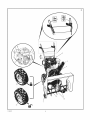 2
2
-
 3
3
-
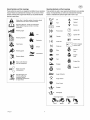 4
4
-
 5
5
-
 6
6
-
 7
7
-
 8
8
-
 9
9
-
 10
10
-
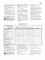 11
11
-
 12
12
-
 13
13
-
 14
14
-
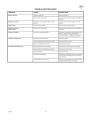 15
15
-
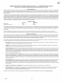 16
16
-
 17
17
-
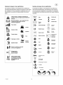 18
18
-
 19
19
-
 20
20
-
 21
21
-
 22
22
-
 23
23
-
 24
24
-
 25
25
-
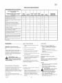 26
26
-
 27
27
-
 28
28
-
 29
29
-
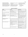 30
30
-
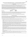 31
31
-
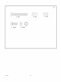 32
32
-
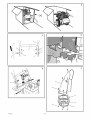 33
33
-
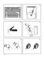 34
34
-
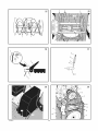 35
35
-
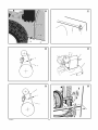 36
36
-
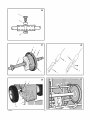 37
37
-
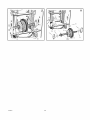 38
38
-
 39
39
-
 40
40


Murray 1695539 Le manuel du propriétaire
- Catégorie
- Souffleuses à neige
- Taper
- Le manuel du propriétaire
dans d''autres langues
- English: Murray 1695539 Owner's manual
Documents connexes
-
Murray 629904X54A Le manuel du propriétaire
-
-
-
-
-
-
Murray TP 199-4955-00-LW-R Manuel utilisateur
-
-
-
Autres documents
-
Simplicity 1696222-00 Manuel utilisateur
-
-
-
-
-
-
Simplicity SNW, DS, CRAFTSMAN Manuel utilisateur
-
-
Bolens 31AE9P3J565 Le manuel du propriétaire
-