Impecca IWA15-KS30 Mode d'emploi
- Catégorie
- Climatiseurs mobiles
- Taper
- Mode d'emploi
Ce manuel convient également à

Window Air Conditioner—User Manual
Aire acondicionado—Manual de usuario
Models:
IWA15-KS30, IWA18-KS30, IWA25-KS30
www.impecca.com
v0.2

Read the following notices and information carefully to ensure proper operation of your air
conditioner unit.
This manual is solely provided for informational purposes and in no way constitutes a legally
binding document between the manufacturer, distributor, and end consumer. Exact appear-
ance of your unit may dier from the pictures and diagrams enclosed.
Lea las siguientes indicaciones cuidadosamente para asegurar el correcto funcionamiento
de su unidad de aire acondicionado.
Este manual se proporciona únicamente con fines informativos y de ninguna manera
constituye un documento jurídicamente vinculante entre el fabricante, distribuidor y
consumidor final. Apariencia exacta de su unidad puede diferir de las imágenes y esque-
mas adjuntos.
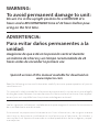
WARNING:
To avoid permanent damage to unit:
Ensure it is in the upright position for a MINIMUM of 6
hours and a RECOMMENDED time of 24 hours before pow-
ering on the first time.
ADVERTENCIA:
Para evitar daños permanentes a la
unidad:
Asegúrese de que está en la posición vertical durante
un mínimo de 6 horas y un tiempo recomendado de 24
horas antes de encender la primera vez.
Spanish version of this manual available for download on
www.impecca.com

ENGLISH
–iii–
TABLE OF CONTENTS
Introduction ..............................................................................................................................6
Getting To Know Your Air Conditioner ..................................................................................7
Using Your Air Conditioner .....................................................................................................8
Delay Start/Stop (Timer) ...................................................................................................... 11
Additional Features and Information ................................................................................ 12
Pre-installation instructions................................................................................................ 13
Window Installation .............................................................................................................. 16
Through-The-Wall Installation ............................................................................................ 23
Masonry Construction .......................................................................................................... 26
R1 Installation of Energy Star Insulation .......................................................................... 27
Cleaning & Maintenance ...................................................................................................... 29
Troubleshooting .................................................................................................................... 30
Customer Support ................................................................................................................. 32
Two-Year Limited Appliance Warranty (US) ...................................................................... 33
Garantía Limitada Por dos Años (US) ................................................................................ 34
Garantie limitée de deux ans (US) ...................................................................................... 35

ENGLISH
–4–
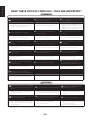
Plug in power plug completely.
Do not start or stop the unit by inserting or
pulling out the power plug.
Do not damage power cord or replace
with a non-original power cord.
• Otherwise, it may cause electric shock or
fire due to potential short circuit.
• It may cause electric shock or fire.
• It may cause electric shock or fire.
• If the power cord is damaged, it must
be replaced by the manufacturer or an
authorized service center or a similarly
qualified person to avoid hazard.
Do not modify power cord length.
Do not operate with wet hands or in a
damp environment.
Do not direct airflow directly at room
occupants.
• It may cause electric shock or fire. • It may cause electric shock. • This could be harmful to their health.
Always ensure eective grounding/
earthing.
Do not allow water into or onto the front of
cabinet, control panel or power cord.
Always use dedicated power outlet and
circuit breaker.
• Incorrect or missing grounding may lead to
electric shock.
• It may cause failure of unit or electric shock. • Sharing a circuit can lead to fire.
Unplug the unit if it emits strange sounds,
smells or smoke.
Do not plug unit into an electrical socket
that is loose or damaged.
Do not operate the unit while the
chassis is open or removed.
• Unit may need repair. • It may cause fire and electric shock. • It may cause electric shock.
Ensure the power cord is kept away from
any heating sources.
Do not disassemble or modify unit.
Do not use the power cord near
flammable gas or combustibles, such as
gasoline, benzene, paint thinner, etc.
• It may cause fire and electric shock. • It may cause failure and electric shock. • It may cause an explosion or fire.
Ventilate room before operating
air conditioner if there was a gas leakage.
• It may cause explosion, fire, and burns.
WARNING
READ THESE NOTICES CAREFULLY—THEY ARE IMPORTANT!
When the air filter is removed for cleaning,
avoid touching the internal metal parts of
the unit.
Do not clean the air conditioner with water.
Ventilate the room well when used
together with a stove, etc.
• It may cause an personal injury and/or
damage to the unit.
• Water may enter the unit and degrade the
insulation. It may cause an electric shock.
• An oxygen shortage may occur when
using a stove in a room with closed
windows.
When the unit is to be cleaned, power o
the unit and circuit breaker.
Do not put a pet or house plant where it
will be exposed to direct air flow.
Do not use for specialized purposes.
• Do not clean unit when power is on as it
may cause fire and electric shock and/or
personal injury.
• This could injure or be harmful
to your pet or plants.
• Do not use this air conditioner to
preserve precision devices, food, pets,
plants, and art objects.
• It may cause deterioration, etc.
CAUTION

ENGLISH
–5–
CAUTION
ELECTRICAL INFORMATION
• Be sure your electrical wiring is adequate for the model you have chosen. This information can be found on
the rating label, a silver-colored sticker generally located on the right side of the cabinet.
• Be sure the air conditioner is properly grounded. To minimize shock and fire hazards, proper grounding is
important. The power cord is equipped with a three-prong
grounding plug for protection against shock hazards.
• Your air conditioner must be connected to a properly ground-
ed wall receptacle. If the wall receptacle you intend to use
is not adequately grounded or protected by a time delay
fuse or circuit breaker, have a qualified electrician install the proper
receptacle.
• Ensure the receptacle is accessible aer the unit installation.
Stop operation and remove unit from
window in severe storm or hurricane.
Hold the plug by the head of the power
plug when unplugging unit.
Unplug the power cord when not using
the unit for extended periods of time.
• Operation during a severe storm may allow
a significant amount of water to enter the
indoors.
• Pulling from the wire can cause wire to fray
leading to electric shock or fire.
• Will prevent damage to the unit.
Do not place obstacles around air-intake
vents or inside cool air outlet.
If unit is equipped with an outdoor
installation bracket, periodically ensure that
it has not become damaged.
Always insert the filters securely.
Clean filter at least once per month.
• It may cause failure of appliance.
• If bracket is damaged, the unit can fall and
cause damage, personal injury or death.
• Operation with dirty filters (or without
filters) will eect performance and may
cause damage to the unit.
Do not use strong detergent such as
wax or paint thinner to clean the unit.
Use a damp, so cloth.
Do not place heavy objects on the
power cord and ensure that the cord
is not pinched or stressed.
Do not place this window-type air
conditioner through a wall.
• Appearance may deteriorate due to change
of product color or scratching of its surface.
• There is danger of fire or electric shock.
• This will block the side vents and pre-
vent the unit from cooling properly.
CAUTION
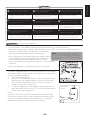
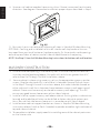
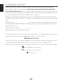
NOTE: The power supply cord with this air conditioner
contains a current detection device designed to reduce the risk
of fire. In the event that the power supply cord is damaged, it
cannot be repaired -- it must be replaced with a cord from the
Product Manufacturer.
The power supply cord contains a current device that senses damage
to the power cord and excess current draw from the unit. To test your
current device do the following:
1. Plug in the Air Conditioner.
2. Press the TEST button. You will hear a click as the RESET button
pops out within the rubber housing and the LED will turn o.
3. Press the RESET button. You will hear a click as the button
engages and the LED will illuminate.
4. The power supply cord is now supplying electricity to the unit.
Note: Your model may have the TEST and RESET buttons on the
side or the front of the plug head.
NOTES:
• Do not use the TEST and RESET buttons to turn the unit on or o.
• If the current device fails the test or the power cord becomes dam-
aged, the entire power cord must be replaced with an equivalent
power cord and current device by a licensed electrician.
Side button
version

ENGLISH
–6–
INTRODUCTION
Thank you for purchasing this quality Impecca window air conditioner unit. To ensure
the longest life and highest energy eiciency of your unit, please carefully follow these
operating instructions. Keep these instructions in a safe place and consult them as
needed. Please note that constant enhancement and improvements to our air condi-
tioning units may mean that your model will slightly dier in appearance from the mod-
el pictured in this manual, but the actual operation and installation of the unit remains
unchanged. This manual is solely provided for informational purposes and does not
constitute a binding, legal contract.
SAFETY NOTICE:
This appliance should not be used by children or mentally/physically disabled persons with-
out strict, direct supervision by a responsible adult. Never play with or around the appliance.
SAFETY INFORMATION
• Before operation, ensure your electrical installation (outlets and circuits) complies
with the power specifications found on the unit.
• Before cleaning or maintaining the air conditioner, please turn o air conditioner and
unplug the unit.
• Make sure the power cord isn’t kinked, bent, or under the weight of sharp or heavy
objects.
• Do not pull or yank the power cord to unplug the unit or move the air conditioner.
• Do not insert or unplug the power plug with wet hands.
• Only use a grounded power outlet. Make sure the grounding is functional.
• If the power cord is damaged, it must be replaced by the manufacturer or a qualified
technician in order to avoid fire and electrical hazards.
• Should abnormal operation occur (such as a burning smell), please disconnect pow-
er cord immediately and contact your local dealer.
• If nobody is present to monitor the operation of the unit, please turn it o and dis-
connect the power cord.
• Do not splash or pour water on air conditioner to avoid causing a short circuit or
damage to the unit.
• Do not put or hang dripping objects above the air conditioner.
• Ensure the ambient temperature remains well above freezing (32°F or 0°C) to avoid
cracking or damaging the unit.
• Keep heat sources away from the air conditioner.
• Ensure the unit is far away from fire, inflammable, or explosive objects.
• Never allow children or persons with reduced physical, sensory, or mental capabili-
ties to operate or play around the air conditioner without direct adult supervision.
• Never allow children to perform cleaning or other user-maintenance operations
without direct adult supervision.
• Never attempt to repair or disassemble the air conditioner by yourself.
• Never insert objects into the air conditioner.

ENGLISH
–7–
OPERATING CONDITIONS
• The air conditioner must be operated within the temperature range of 62°F to 95°F
(16°C to 35°C).
• A perimeter of 12′′ (30cm) around the air conditioner should be free of all objects.
• Keep air inlet and air outlet clean and free of obstructing objects.
• During operation, close doors and windows to improve cooling eect.
• Please put the air conditioner at smooth and flat ground for operation to avoid noise
and vibration.
• Do not tilt or turn over the air conditioner. If there’s problem, please disconnect the
power supply immediately and contact your local dealer or technical support.
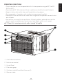
GETTING TO KNOW YOUR AIR CONDITIONER
1. Cool air directional levers
2. Fresh air vent control
3. Control Panel
4. Filter cover grasps
5. Outside air intake (Do not block these vents!)
6. Warm air intake
B
C
D
E
F
G

ENGLISH
–8–
USING YOUR AIR CONDITIONER
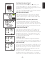
OVERVIEW OF CONTROLS FUNCTIONS
Before you begin, thoroughly familiarize yourself with the control panels as shown below
and all its functions, then follow the symbol for the functions you desire. The unit can be
controlled by the unit control panel located on the front of the device or with the remote
controller.
B
C
D
E
F
G
H I
J
K
L
M
Ion
PMTS
1. Temperature/Timer Up
2. Energy Saver Mode (Toggle O and On)
3. Ion - Clean Air Feature
4. Display (Temperature/Timer)
5. Temperature/Timer Down
6. Function selector (Auto-Cool-Dry-Fan)
7. Timer (Delay start/stop)
8. Fan Speed selector
9. Infrared Remote senor window
10. Power On/O
11. Check Filter light reset
12. Sleep mode
Note that your model's control panel may dier slightly.
POWER ON/OFF
Press the On/O button to turn the unit on or o.
CLEAN AIR (ION) FEATURE
Available on certain models, the ion generator
creates an energized field and will help to remove
pollen and impurities from the air, trapping them in
the filter.
Ion

ENGLISH
–9–
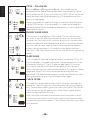
TEMPERATURE ADJUSTMENT
Press or hold either Down or Up button until
the desired temperature is seen on the display. This
temperature will be automatically maintained anywhere
between 62° F (17° C) and 86° F (30° C).
If you want the display to read the actual room tempera-
ture, refer to "FAN ONLY MODE" below.
FAN SPEED ADJUSTMENT
Select the Fan Speed in four steps: Auto, Low, Med or
High. Each time the button is pressed, the fan speed
mode is shied. During Dry mode, the fan speed is kept
at Low automatically.
OPERATING MODE (FUNCTION) SELECTION
To choose operating mode, press the Mode button.
Each time you press the button, a mode is selected in a
sequence that goes from AUTO, COOL, DRY, and FAN. The
indicator light beside will be illuminated and will remain
on once the mode is selected.
USING AUTO FEATURE
When you set the air conditioner in AUTO mode, it will
automatically select cooling or fan only operation de-
pending on the current room temperature and the target
temperature you have set. The air conditioner will con-
trol room temperature automatically. In this mode, the
fan speed cannot be adjusted.
USING DRY MODE
In this mode, the air conditioner will generally operate in
the form of a dehumidifier. Since the conditioned space is a
closed or sealed area, there will be some degree of cooling.
FAN ONLY MODE
Use this function only when cooling is not desired, such as
for room air circulation or to exhaust stale air. Remember
to open the vent during this function, but keep it closed
during cooling for maximum cooling eiciency. You can
choose any fan speed you prefer.
During this function, the display will show the actual room
temperature, not the set temperature as in the cooling
mode. In Fan Only mode, the temperature is not adjusted.

ENGLISH
–10–
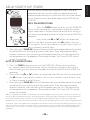
PMTS — FOLLOW ME
Personal Mapping Temperature Sensor: Your model may be
equipped with a special feature that allows the remote control to
act as a thermostat. If your unit shows this PMTS LED on the control
panel, and you have the accompanying LCD remote control then
your unit is equipped.
You must activate this feature through the remote control by press-
ing the PMTS button. Once activated, it is important to keep the
remote aimed at the air conditioner and place it in the center of the
room for best results.
ENERGY SAVER MODE
This function is available on COOL mode. The fan will continue
to run for 3 minutes aer the compressor shuts o. The fan then
cycles on for 2 minutes at 10-minute intervals until the room tem-
perature is above the set temperature, at which time the compres-
sor turns back on and Cooling Starts. Note that due to modern
energy saving regulations, this mode is on by default and you
must turn it o if you want the fan to run constantly during cooling
mode.
SLEEP MODE
In this mode the selected temperature will increase by 2°F (or 2°C)
30 minutes aer the mode is selected. The temperature will then
increase by another 2°F (or 2°C) aer an additional 30 minutes.
This new temperature will be maintained for 6 hours before it
returns to the originally selected temperature. This ends the Sleep
mode and the unit will continue to operate as originally pro-
grammed. The Sleep mode program can be canceled at any time
during operation by pressing the Sleep button again.
CHECK FILTER
This feature is a reminder to clean the Air Filter for more eicient
operation. The LED (light) will illuminate aer 250 hours of opera-
tion. To reset aer cleaning the filter, press the Check Filter button
and the light will go o. See section under Cleaning and Mainte-
nance for how to clean the filter.
Note: Your filter may need to be cleaned much more oen in espe-
cially dusty environments and may not need to be cleaned as oen
in especially clean environments. The 250 hour indicator is just there
as a reminder.
Ion
PMTS
PMTS
PMTS

ENGLISH
–11–
DELAY START/STOP (TIMER)
The timer buttons enable two separate functions: one to au-
tomatically start the unit within a 24 hour period of time and
another to automatically turn o the unit within a 24 hour period
of time. These functions are called, respectively, AUTO ON and
AUTO OFF.
AUTO ON INSTRUCTIONS:
1. Press the TIMER button twice, or until the TIMER ON
LED on the air conditioner's control panel should illuminate.
The air conditioner's display shows the last Auto-On setting (if
any). Now you are ready to reset the Auto-On time to START the
operation.
2. Press either the or buttons to set desired
Auto-On time. Each time you press the button, the time
will increase in 30 minute increments, up to 10 hours, then in 1
hour increments up to 24 hours.
3. Aer setting the TIMER ON, there will be a one-half second delay before the remote
controller transmits the signal to the air conditioner. Then, aer approximately
another 2 seconds, the time setting will disappear from the unit's display and the
set temperature will re-appear on the display window. The Timer ON LED should
remain illuminated.
AUTO OFF INSTRUCTIONS:
1. Press the TIMER button once, or until the TIMER OFF LED on the air condition-
er's control panel should illuminate. The air conditioner's display shows the last
Auto-O setting (if any). Now you are ready to reset the Auto-O time to START the
operation.
2. Press either the or buttons to set desired Auto-O time. Each time you press
the button, the time will increase in 30 minute increments, up to 10 hours, then
in 1 hour increments up to 24 hours.
3. Aer setting the TIMER ON, there will be a one-half second delay before the remote
controller transmits the signal to the air conditioner. Then, aer approximately
another 2 seconds, the time setting will disappear from the unit's display and the
set temperature will re-appear on the display window. The Timer OFF LED should
remain illuminated.
Notes: It is possible to set both and Auto-On and Auto-O program at the same time. All times that are set are
the time from the moment of setting. So if you were to set a delay of 5 hours to turn on and immediately aer
set a delay of 6 hours to turn o, then the unit will operate for a total of 1 hour in 5 hours time from now.
All programs are erased aer their time elapses, so they will not repeat again the next day until reprogrammed.
Important: If you use a separate timer to obtain more control (such as turning on and o at a specific time every
day), the unit will remember its previous mode. It may, however, return to energy saver mode by default. If you
do use a timer, be sure that it is a heavy -duty grounded (three-prong) timer that is rated for the appropriate
amperage.

ENGLISH
–12–
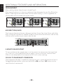
ADDITIONAL FEATURES AND INFORMATION
FRESH AIR VENT
When cooling, always leave the vent closed (Fig. A).
When operating the unit in fan only mode, you may also open the vent (Fig. B) Another
option is opening the vent and exhaust at the same time(Fig. C), which is good for re-
moving odors from the room during fan mode.
AIR DIRECTION(4-WAY)
The 4-way air directional louvers allow you to direct the air flow Up or Down and Le or
Right throughout the room as needed. To adjust the air directional louvers side-to-side,
use the center handles as you move it side-to-side.
3-MINUTE DELAYED START
This air conditioner has a protection circuit to prevent the compressor from overheat-
ing. If the unit is switched o and then on again in quick succession, there will be a
three-minute delay before the compressor will kick in (when cooling).
CELSIUS TO FAHRENHEIT CONVERSION
The temperature display is capable of showing the units in either Fahrenheit or Celsius.
To toggle between options, press and hold the Up and Down buttons at the
same time for three seconds.
Fig. A
Fig. B
Fig. C

ENGLISH
–13–
1 2
3
7
9
8 11
13
12
14 15 16
4
3
5
6
10
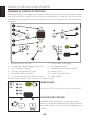
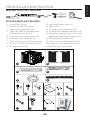
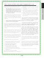
PRE-INSTALLATION INSTRUCTIONS
REQUIRED TOOLS (NOT INCLUDED)
INCLUDED PARTS & ACCESSORIES*
1. Air conditioning unit
2. Flexible window filler panels
3. Upper Rail Angle Bracket (x1)
4. Upper Rail seal (may already be af-
fixed to bottom of rail) (x1)
5. Foam sash seal (no adhesive) (x1)
6. Foam seal (with adhesive) (x1)
7. 7/16" locking screw with flat washer (x2)
8. ¾” (or ½”) length hex-head screw (x7)
9. Sill angle bracket (x2)
10. Right-angle Safety Lock (x1)
11. Foam insert
12. ½” length screw and locknut (x4)
13. ¾” length flat head bolt and locknut (x2)
14. Longer hex-head locking screw for top
angle bracket and side retainers (x10)
15. R1 energy star hardware (x2)
16. User’s manual and Remote Manuals
*Note: The parts and appearance of parts
included with your unit may vary.
Phillips Screwdriver
Level
Scissors
Pencil Drill
drill bits
3/32”
1/8”
Tape Measure

ENGLISH
–14–
UNIT CHASSIS EXPLODED VIEW
Window Sash Seal
Safety Lock and
¾” (or ½”) length Hex Head Screw
Foam Gasket
Upper Rail
Washer Head
Locking Screw
Frame
Assembly
(Le)
Frame
Assembly
(Right)
Side Retainer
Bottom rail
seal
½”
length Screw
and Locknuts
Locknut
¾” Long
Flat Head
Bolt
Sill Angle
Bracket
Window Support
Bracket

ENGLISH
–15–
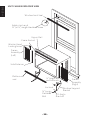
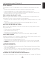
WINDOW REQUIREMENTS
Your air conditioner is designed
to be installed in standard
double hung windows with
minimum width and height
requirements as follows:
W: Opening widths of 28 inches
(for 15K and 18K models) or 31
inches (25K models).
H: Opening height of 18.5 inch-
es (for 15K and 18K models) or
19.5 inches (25K Models).
STORM WINDOW MODIFICATIONS
If you have storm windows, the exterior window frame will be slightly higher than the
windowsill, which results in an air conditioning unit that is slanted inward and may
cause water condensation to enter the room interior. Perform these modifications to
ensure proper operation of your unit. If you have a standard window, skip this step:
1. Cut a 2” thick piece of wood to the length of the interior window width.
2. Verify that the wood is level with or up to 0.5” (1cm) higher than the exterior
storm-window frame.
3. Fasten the wood with screws to the windowsill and proceed with mounting.
Exterior Wall
Board thickness
should be as required
for proper pitch and
run along the entire
window sill. Fasten
with nails or screws.
Storm Window
or other obstruction
½” min
H
Wooden Windows
INTERIOR
WALL
INNER
WINDOW SILL
EXTERIOR
WALL
OFFSET
W

ENGLISH
–16–
WINDOW INSTALLATION
Use caution when unpacking and installing. Sharp edges can cause injury.
Appearance of unit in these diagrams is for illustrative purposes only and may not precisely
reflect your unit’s design.
BEFORE YOU BEGIN
1. Check for anything that could block airflow: Any shrubs, trees, awnings on the
outside; blinds, drapes, furniture, etc. on the inside. It is critically important that
none of the outside vents (sides or rear) be blocked by anything including installing
this air conditioner in an existing enclosure or through a wall that is so thick that the
outside side vents get blocked. Any of these blockages will reduce or even eliminate
the eectiveness of all functions besides the Fan Only mode.
2. Make sure you have met the electrical requirements of the unit: Your unit
should have a dedicated outlet nearby. The cord length is 78 inches. Each unit has
the power requirements and plug type listed on the box and also on the silver rating
label aixed to the right-hand-side of the unit itself. It is important to note that if
you have a 208/230Volt unit, a qualified electrician will be required to install a new
outlet, breaker and possibly wiring. A new outlet alone will not work without these
other upgrades. Do not use an extension cord with this unit.
3. Be careful when unpacking the unit and get assistance from a second person:
Care should be taken to always keep the unit upright. Remember, if the unit was
shipped to you on its side or upside-down, be sure to keep it in the upright position
for 24 hours before use.
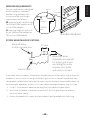
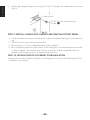
STEP 1: REMOVAL OF THE CHASSIS
This larger air conditioner requires that you remove the unit (chassis) from its housing
(cabinet), install the cabinet in the window (or wall), cut some internal packing materials,
and then slide the chassis back into the cabinet. The instructions that follow will take you
through everything in order. It is important to follow all of the steps presented here.
1. Pull down the front grille and remove the air filter (See Fig. A).
2. Li the front grille upwards to dislodge it from the chassis and place to once side.
3. Locate the four front screws securing the front panel and remove. Guard these
screws as they will later be needed to reinstall the front panel (See Fig. B)
4. The front panel is additionally held in place by plastic clips. To dislodge the panel,
push the plastic outwards while grasping the metal cabinet. Do this in the top and
Front Grille
Front Panel
Fig. A
Fig. B

ENGLISH
–17–
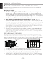
bottom le side and repeat on the right side. Gently dislodge, noting that the con-
trol panel will be connected to the main unit (Figures C, D).
5. Disconnect the connector plug of the control panel and place the front panel to one
side, with the control panel still attached (Fig. E)
6. Remove the shipping screws from the top of the cabinet and any that may be in-
stalled on the side of the base (Fig. F).
7. The shipping screws are not needed for the rest of this installation procedure. Cover
over the holes on the top of the cabinet with the two included foam inserts (Fig. G).
8. Your unit may have shipped
with internal packaging that
protected the compressor
from damage during shipping
(Fig. H). If so, now is the time
to remove this packaging by
cutting the plastic tie.
Fig. C Fig. D
Fig. E
Shipping Packaging
Plastic tie
shipping
screws
Fig. F Fig. G
Fig. H

ENGLISH
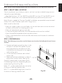
–18–
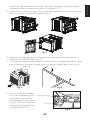
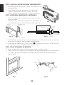
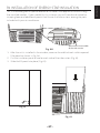
STEP 2: INSTALL UPPER RAIL AND SIDE BRACKETS
1. Aix foam gasket to bottom of upper rail bracket (if not
already aixed).
2. Install upper rail and side retainers to cabinet as
shown using a total of 10 5/16” screws, with the
screws being inserted from the inside of the cabinet.
STEP 3: ASSEMBLE WINDOW FILLER PANELS
1. Place the cabinet on a steady surface such as a floor,
bench or table.
2. Slide I section of window filler panel into side retainer on
the side of the cabinet. Do this for both sides (Figs. J, K).
3. Slide the filler panel’s horizontal top and bottom rails into the channels on both the
bottom of the cabinet and the upper angle bracket.
4. Insert washer head locking 7/16” screws( H). Do not overly tighten – allow the rails
to move freely. You will tighten them during step 6.
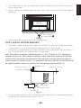
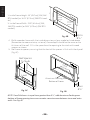
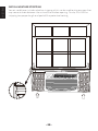
STEP 4: PLACE CABINET IN WINDOW
1. Open window and mark center of window stool as shown in Fig. L.
2. Place cabinet in window with the bottom stool angle seated over the window stool
as shown. Bring window down temporarily behind upper rail to hold cabinet in
place (Fig. M).
5/16” length
hex-head
Fig. I
Plastic
Frame
Window Filler
Panel
Side Retainer
Top
View
Air Conditioner
Cabinet
Plastic
Frame
“I” Section
Window
Filler Panel
Locking
Screw Hole
Fig. J Fig. K
Stool
Stool
Angle
Fig. L Fig. M

ENGLISH
–19–
3. Shi cabinet le or right as needed to line up the center on the line you marked on
the window stool.
4. Fasten cabinet to window stool with two screws. (You may wish to drill pilot holes in
advance.)
5. Add bottom rail seal over screws to window stool.
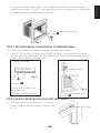
STEP 5: INSTALL SUPPORT BRACKETS
1. Hold each support bracket flush against outside of sill, and tight to bottom of cabi-
net as shown in Fig. P. Mark brackets at top level of sill, and remove.
2. Assemble sill angle bracket to support brackets at the marked position as shown in
Fig. Q. Hand tighten, but allow for any changes later.
Note: The cabinet should be tilted back about 1 ¼” to 1 ⅝” (about 3° to 4° downward
towards the outside. Aer proper installation, water should not drain out of the back
of the unit but should be evaporated with the help of the rear fan splashing a pool of
water up onto the condenser coils. It is important, however, that the air conditioner not
be sloped inward as water can spill into the room being conditioned (Fig. O).
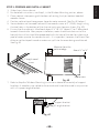
3. Install support brackets (with sill angle brackets attached) to the appropriate hole in
the bottom of the cabinet as shown in Fig. R.
Bottom
Rail Seal
¾” (or ½”) length
Hex-Head Screw I
5
Window Sash
Side Louvers
Sill Angle Bracket
Window Sill
About 1¼” to 1⅝”
Measure from
the cabinet edge
Fig. N
Fig. O

ENGLISH
–20–
4. Tighten all 6 bolts securely.
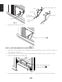
STEP 6: EXTEND WINDOW FILLER PANELS
1. Carefully raise window sash to expose filler panel locking screws. Loosen screws so
filler panels slide easily.
2. Extend panels to fill window opening completely. Tighten locking screws on top.
3. Close window behind upper rail.
4. Secure the upper rail to the window frame. Using a 3/32” drill bit, drill one hole
Mark
Le
Right
Sill Angle
Bracket
Flat Head
Screw
Locknut
12” Screws and nuts
Fig. P
Fig. Q
Fig. R
Fig. S
½” Screws and Nuts L
7/16” Locking screw
with washer (H)
Locking Screws
La page est en cours de chargement...
La page est en cours de chargement...
La page est en cours de chargement...
La page est en cours de chargement...
La page est en cours de chargement...
La page est en cours de chargement...
La page est en cours de chargement...
La page est en cours de chargement...
La page est en cours de chargement...
La page est en cours de chargement...
La page est en cours de chargement...
La page est en cours de chargement...
La page est en cours de chargement...
La page est en cours de chargement...
La page est en cours de chargement...
La page est en cours de chargement...
-
 1
1
-
 2
2
-
 3
3
-
 4
4
-
 5
5
-
 6
6
-
 7
7
-
 8
8
-
 9
9
-
 10
10
-
 11
11
-
 12
12
-
 13
13
-
 14
14
-
 15
15
-
 16
16
-
 17
17
-
 18
18
-
 19
19
-
 20
20
-
 21
21
-
 22
22
-
 23
23
-
 24
24
-
 25
25
-
 26
26
-
 27
27
-
 28
28
-
 29
29
-
 30
30
-
 31
31
-
 32
32
-
 33
33
-
 34
34
-
 35
35
-
 36
36


Impecca IWA15-KS30 Mode d'emploi
- Catégorie
- Climatiseurs mobiles
- Taper
- Mode d'emploi
- Ce manuel convient également à
dans d''autres langues
- English: Impecca IWA15-KS30 User guide
Documents connexes
-
Impecca IWAH08KRA Mode d'emploi
-
-
-
-
-
-
-
-
-
Autres documents
-
LG LW8016ER Le manuel du propriétaire
-
-
-
Haier CWH18A Manuel utilisateur
-
RCA RACE5002E Mode d'emploi
-
-
LG LW6017R Le manuel du propriétaire
-
-
Frigidaire FFRE2233S2 Guide d'installation
-
Frigidaire FHWE232WB2 Mode d'emploi