
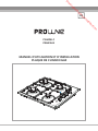
OPERATING AND INSTALLATION
INSTRUCTIONS OF
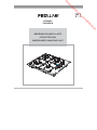
BUILT-IN GAS ON GLASS HOB
EN
PGH4W-F
PGH4SS-B
Downloaded from www.vandenborre.be

Dear Customer,
Our goal is to offer you products with high quality that exceed your expectations.
Your appliance is produced in modern facilities carefully and particularly tested for
quality.
This manual is prepared in order to help you use your appliance that is manufactured
by the most recent technology, with confidence and maximum efficiency.
Before using your appliance, carefully read this guide that includes the basic
information for right and safe installation, maintenance and use. Please contact to
the nearest Authorized Service for the installation of your product.
CE Declaration of conformity
This appliance has been designed to be used only for home cooking. Any other use
(such as heating a room) is improper and dangerous.
This appliance has been designed, constructed, and marketed incompliance with:
• Safety requirements of the "Gas" Directive 2009/142/EC;
• Safety requirements of the "Low voltage" Directive 2006/95/EC;
• Safety requirements of the "EMC" Directive 2004/108/EC;
• Requirements of the Directive 93/68/EC.
Downloaded from www.vandenborre.be

2
CONTENTS:
1. BRIEF PRESENTATION OF PRODUCT
2. SAFETY WARNINGS
3. INSTALLATION AND PREPARATIONS FOR USE
3.1
3.3 Gas connection
3.4 Electric connection and safety
3.5 Gas conversion
4. USE OF YOUR PRODUCT
4.1 Use of gas burners
4.2 Use of hotplate
4.3 Accesorries
5. CLEANING AND MAINTENANCE
5.1 Cleaning
5.2 Maintenance
6. SERVICE AND TRANSPORT
6.1
6.2 Information related to the transport
Environment where your appliance will be installed
Basic troubleshooting before contacting service
3.2 Installation of product
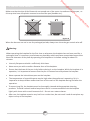
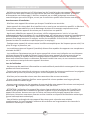
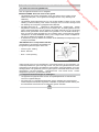
Attention: Each burner of your hob is fitted with a thermocouple safety device, in compliance with
the new legislation.
A thermal component detects the burner flame and holds the gas open. In case the flame
disappears (because a liquid overflew or there was a draught, for example), the thermal component
detects heat loss and cuts the gas inlet off from the gas valve.
To ignite a burner:
Turn the gas burner control button to maximum position. Ignite the burner with a match or lighter
or with the electric ignition button, and continue pressing the button for a few seconds (maximum
10 seconds). Release the button and make sure the flame is stable. If it's not, wait a few moments
(about 40 seconds) and repeat the process.
Downloaded from www.vandenborre.be

3
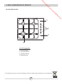
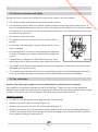
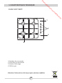
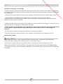
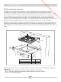
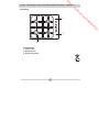
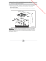
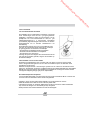
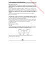
1. BRIEF PRESENTATION OF PRODUCT
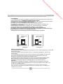
List of Components:
Gas Hob & Mixed Hob
* The appearance of your hob may be different than the model shown above due to its configuration.
1-
2- Control buttons
3- Ignition button
4- Rapid Burner
Control panel
1
4
3
2
Downloaded from www.vandenborre.be

4
2. SAFETY WARNINGS
READ THESE INSTRUCTIONS CAREFULLY AND COMPLETELY BEFORE USING YOUR
APPLIANCE, AND KEEP IT IN A CONVENIENT PLACE FOR REFERENCE WHEN NECESSARY.
THIS MANUAL IS PREPARED FOR MORE THAN ONE MODEL IN COMMON. YOUR APPLIANCE
MAY NOT HAVE SOME OF THE FEATURES THAT ARE EXPLAINED IN THIS MANUAL. PAY
ATTENTION TO THE EXPRESSIONS THAT HAVE FIGURES, WHILE YOU ARE READING THE
OPERATING MANUAL.
General Safety Warnings
- This appliance is intended for domestic
household use only and should not be used for
any other purpose or in any other application,
such as for non-domestic use or in a
commercial environment.
- This appliance can be used by children aged
from 8 years and above and persons with
reduced physical, sensory or mental capabilities
or lack of experience and knowledge if they
have been given supervision or instruction
concerning use of the appliance in a safe way
and understand the hazards involved. Children
shall not play with the appliance. Cleaning and
user maintenance shall not be made by children
without supervision.
- If the supply cord is damaged, it must be
replaced by the manufacturer, its service agent
or similarly qualified persons in order to avoid a
hazard.
- WARNING: The appliance and its accessible
parts become hot during use. Care should be
taken to avoid touching heating elements.
Downloaded from www.vandenborre.be

5
2. SAFETY WARNINGS
Children less than 8 years of age shall be kept
away unless continuously supervised.
- WARNING: Unattended cooking on a hob with
fat or oil can be dangerous and may result in
fire. NEVER try to extinguish a fire with water,
but switch off the appliance and then cover flame
e.g. with a lid or a fire blanket.
- WARNING: Danger of fire: do not store items
on the cooking surfaces.
-The appliance is not intended to be operated by
means of an external timer or separate remote-
control system.
-Do not use steam cleaners for cleaning the
appliance.
General safety instructions
-Your appliance is produced in accordance with all applicable local and international standards and
regulations.
- Maintenance and repair work must be made only by authorized service technicians. Installation and
repair work that is carried out by unauthorized technicians may endanger you. It is dangerous to alter or
modify the specifications of the appliance in any way.
- Prior to installation, ensure that the local distribution conditions (nature of the gas and gas pressure or
electricity voltage and frequency) and the requirements of the appliance are compatible. The
requirements for this appliance are stated on the label.
- CAUTION: This appliance is designed only for cooking food and is intended for indoor domestic
household use only and should not be used for any other purpose or in any other application, such as
for non-domestic use or in a commercial environment or room heating.
- This appliance is not connected to a combustion products evacuation device. It shall be installed and
connected in accordance with current installation regulations. Particular attention shall be given to the
relevant requirements regarding ventilation.
- If after 15 s the burner has not lit, stop operating the device and open the compartment door and/or
wait at least 1 min before attempting a further ignition of the burner.
- These instructions are only valid if the country symbol appears on the appliance. If the symbol does
not appear on the appliance, it is necessary to refer to the technical instructions which will provide the
necessary instructions concerning modification of the appliance to the conditions of use of the country.
- Ensure that the supply cord is not wedged during the installation. If the supply cord is damaged, it
must be replaced by the manufacturer, its service agent or similarly qualified persons in order to prevent
a hazard.
Downloaded from www.vandenborre.be

6
2. SAFETY WARNINGS
Installation Warnings
- Do not operate the appliance before it is fully installed.
- The appliance must be installed by an authorized technician and put into use. The producer is not
responsible for any damage that might be caused by defective placement and installation by
unauthorized people.
- When you unpack the appliance, make sure that it is not damaged during transportation. In case of
any defect; do not use the appliance and contact a qualified service agent immediately. As the
materials used for packaging (nylon, staplers, styrofoam...etc) may cause harmful effects to children,
they should be collected and removed immediately.
- Protect your appliance against atmospheric effects. Do not expose it to effects such as sun, rain,
snow etc.
- The surrounding materials of the appliance (cabinet) must be able to withstand a temperature of min
100°C.
During usage
- Do not put flammable or combustible materials, in or near the appliance when it is operating.
- Always position pans over the centre of the cooking zone, and turn the handles to a safe position so
they cannot be knocked or grabbed.
-If you will not use the appliance for a long time, keep the main control switch off. Also when you do
not use the appliance, keep the gas valve off.
- Make sure the appliance control knobs are always in the (stop) position when it is not used.
- CAUTION: The use of a gas cooking appliance results in the production of heat, moisture and
products of combustion in the room in which it is installed. Ensure that the kitchen is well ventilated
especially when the appliance is in use, keep natural ventilation holes open or install a mechanical
ventilation device (mechanical extractor hood).
- Prolonged intensive use of the appliance may call for additional ventilation, for example opening of a
window, or more effective ventilation, for example increasing the level of mechanical ventilation where
present.
During cleaning and maintenance
- Always turn the gas valve off before operations such as cleaning or maintenance. You can do it after
plugging the appliance off or turning the main switches off.
- Do not remove the control knobs to clean the control panel.
TO MAINTAIN THE EFFICIENCY AND SAFETY OF YOUR APPLIANCE, WE RECOMMEND YOU
ALWAYS USE ORIGINAL SPARE PARTS AND TO CALL ONLY OUR AUTHORIZED SERVICE
AGENTS IN CASE OF NEED.
Downloaded from www.vandenborre.be

7
3. INSTALLATION AND PREPARATIONS FOR USE
This modern, functional and practical hob, that was manufactured with the parts and materials of
highest quality, will meet your cooking needs in every aspect. You must surely read this manual so
that you don't have any problem in future and to be able to have satisfactory results. The following
information are the required rules for right installation and service processes. It must be read
especially by the technician who will install the appliance
Contact to Authorized Service for installation of your product
After removing the packaging, check that your product has no default. If a defect is suspected, do
not use the hob and contact a qualified technician or the shop seller. This hob was designed to be
embedded in a work plan. It connects to a power source using the cable provided for this purpose.
The user of this unit is also responsible for the installation and start-up, according to this record,
according to safety standards and norms.
Your product must be set up and used in a place where it will always have ventilation
.
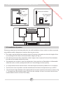
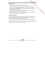
3.1 Environment where your appliance will be installed
• .
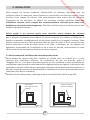
• While operating, this appliance needs 2m3/h air per kw input.
• Gas combustion is made possible by the oxygen in the air. It is therefore necessary that the air
be renewed and that combustion products be discharged in accordance with the regulations.
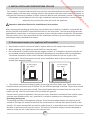
The natural ventilation of the room must be sufficient to allow for the use of gas in this
environment. The airflow must enter via vents installed on walls in direct contact with the
outside (see diagram below).
!
Air inlet section
2
min. 100cm
Air inlet section
2
min. 100cm
Figure 1
Figure 2
• The airflow must enter through a lower vent and go out of an upper vent. These vents must
therefore have a minimum area of 100cm² for the effective passage of airflow. These vents should
be permanently open and never closed. They should preferably be located near the rear of the
cooker (see fig. 1 and 2) and at least 1.80 cm above the ground..
If these vents cannot be opened or there are no vents, alternative ventilation from another room
must be used (window, door, etc.) provided it is neither a bedroom nor a dangerous place.
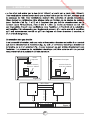
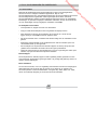
Evacuating burnt gases
The cooking appliances that operate with gas, throw the burned gas wastes out directly to the
outside or through the cooker hoods that are connected to a chimney that opens directly to the
outside. If it seems not possible to install a cooker hood, it is required to set an electric fan on the
window or wall that has access to fresh air. This electric fan power supply must be calculated in
order to renew the air in the kitchen 4-5 times per hour
Downloaded from www.vandenborre.be

8
3. INSTALLATION AND PREPARATIONS FOR USE
Cooker hood
flue
Electrical ventilator
Air inlet section
2
min. 100cm
Air inlet section
2
min. 100cm
Figure 3
Figure 4
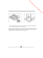
3.2 Installation of product
.
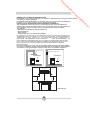
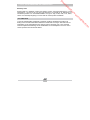
• The cooker may be placed near another piece of furniture, but make sure that the height of the
surrounding furniture does not exceed cooker height (see fig. 5).
• If the kitchen furniture does exceed the cooker height, leave a space of at least 10cm between
the sides of the cooker and the furniture.
•
.
• .
• 100°C.
• The minimum height between the cooktop and the extractor hood (or wall units) is shown in fig
5. The hood must be located at least 65cm from the cooktop. If there is no hood, the furniture
located above must be at least 70cm away.
Please pay attention to the below advice for the safe installation of your cooker in order to prevent
any problems and/or dangerous situations that may occur later
Pay attention not to place it near the refrigerator, there must be no flammable or inflammable
materials such as curtain, waterproof cloth, etc. that will begin to burn quickly
It is required that there must be least a 2cm blank space around the product for air circulation
The furniture close to product must be manufactured resistant to temperatures up to
Figure 5
Min. 60cm
COOKER HOOD
Min. 42cm
Min. 42cm
Min. 65cm(with hood)
Min. 70cm(without hood)
Downloaded from www.vandenborre.be

9
3. INSTALLATION AND PREPARATIONS FOR USE
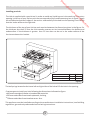
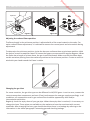
Installing your hob
The Hob is supplied with a special seal in order to avoid any liquid ingress in the work top. Cut out an
opening in the top of your kitchen unit that corresponds to the measurements given in figure. Apply
the self adhesive seal to all edges of the section and carefully fit the hob into the opening in such a way
that the knobs will be on the right side.
The thickness of the top of your kitchen unit must be between the dimensions given in the figure. For
the thickness less than 25 mm the thick wooden spacers can be inserted between the bracket and
undersurface. If the thickness is greater than 25 mm slots can be cut in the under surface of the
furniture to house the bracket.
Figure 6
Wall A[mm] B[mm]
Combustible 60 150
Non-combustible 25 40
510 mm
Min.
A
490 mm
Min.
B
Min.
130mm
Min.
25mm
580 mm
560 mm
42 mm
The leaf springs located on the lower left and right sides of the hob will fix the hob in the opening.
Create a space to install your hob, following the dimensions indicated on figure.
•
100 mm from edge of cooker to combustible materials.
•
700 mm underside of overhead cupboards, shelving
•
750mm underside of overhead extractor fans.
This appliance must be installed according to the manufacturers installation instructions, local building
regulations, gas authority codes and electrical wiring instructions.
Downloaded from www.vandenborre.be

3. INSTALLATION AND PREPARATIONS FOR USE
10
3.3 Gas connection
Connecting gas and checking leakage
Cooker gas connection must also be done by a qualified technician in compliance with current
standards (according to Article 10 of the Order of 02-08-1977 and D.T.U 61-1 rules requiring on the
pipe-end the presence of a control valve for natural gas with a pressure-release compliant with NF
D 36-303 standard. This control valve serves to cut the gas supply when the cooker is not used).
First check what type of gas is installed on the cooker. This information is given by a sticker
underneath the hotplate. You can find information on the types of gases and injectors in the
technical data table. Check that the feeding gas pressure is compliant with values on the technical
data table, to be able to get the most efficiency and to ensure the least consumption. If the
pressure of used gas is different than these values or variable, it is required to affix an available
pressure regulator on the entrance pipe. It is required to contact the customer service to make
these adjustments.
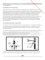
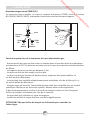
Connecting butane gas (G30) - propane (G31)
The technician will first check the gas adjustment on your hotplate. If it is supplied in natural gas, he
must change the injectors (see below) to make it usable by butane gas. Installation can be done
either with a specific butane/propane gas pipe sold with 2 clips or with a specific TFEM hose
mounted with fittings.
If you mount a butane/propane pipe with collar, the butane gas tip with gas seal will be installed on
the cooker, the pipe will be deeply fitted on this tip and a collar will be installed by tightening
properly, but without cutting the pipe. Do same for valve (see fig. 7).
The required maximum length is 1.5m. It is very important to check the expiry deadline stated on
the pipe and change the pipe before that date to ensure safety.
If you mount a TFEM hose, the butane gas tip is unnecessary. Just screw the TFEM hose fittings
below the hotplate and bottle side (tighten properly using 2 keys as shown in diagram above)
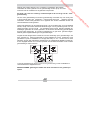
Figure 7
Seal
TFEM
adaptor
TFEM
BG
Butane
Gas
Natural
Gas
TFEM
NG
Downloaded from www.vandenborre.be

3. INSTALLATION AND PREPARATIONS FOR USE
11
Connecting natural gas (G20/G25)
The technician must install a mechanical pipe tip (TFEM) according to NF D 36100/36103/36121
standard and connect the hotplate according to current standards
Please pay attention to the following points when connecting the hose:
• No part of the hose must come into contact with a surface with heat above 50°C (the minimum
distance between the hose and the hot parts must be 20mm).
• Hose length must not exceed 1.5m.
• The pipe must not be ruptured, be tightened or be folded.
• The hose must not touch to the sharp corners, mobile objects, and must not be defective.
• The hose must be thoroughly checked before mounting to ensure there is no manufacturing
defect.
• When the gas is connected, the pipe sealing should be checked with a specific bubble product
by a qualified technician. No bubble should appear. If there are bubbles, check the connection
joint and redo the test. Never use a lighter, match, etc… while conducting this check.
• The tightening butane gas pipe collars must be rust-free.
• The hose validity date should be checked regularly.
Warning: Do not use naked light sources to check for gas leakage.
Downloaded from www.vandenborre.be

3. INSTALLATION AND PREPARATIONS FOR USE
12
Figure 8
•
•
.
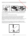
3.5 Gas conversion
:
Changing injectors:
• .
•
•
•
The supply cord should be kept away from hot parts of appliance. Otherwise, the cord may be
damaged, causing short circuit.
The manufacturer declares that it has no responsibility against any kind of damages and losses
that are caused by improper connections that are performed by unauthorized people
Caution: The following procedures must be undertaken by authorized service people.
Your appliance is adjusted to be operated with LPG/NG gas. The gas burners can be adapted to
different types of gas, by replacing the corresponding injectors and adjusting minimum flame length
suitable to the gas in use. For this purpose, following steps should be performed
Cut off the main gas supply and unplug from the electric mains
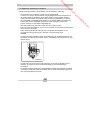
Remove the burner cap and crowns (Figure 11).
Unscrew the injectors. For this, use a 7mm spanner(Figure 9).
Replace the injector with the ones from the gas conversion kit, with corresponding diameters
suitable to the type of gas that is going to be used, according to the information chart (which is
also supplied in the gas conversion kit).
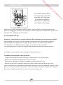
3.4. Electric connection and safety
.
• .
•
• .
•
•
.
•
.
•
.
During the electric connection, follow the instructions stated in the user manual
The earthing cable must be connected to the earth terminal
Ensure that the mains cable has suitable insulation before connecting to the power source. If
there is no appropriate earthed electric outlet in accordance with regulations in the place where
the appliance to be installed, contact to our authorized service. The earthed electric outlet must
be close to the appliance.
Do not use an extension cord
The power cord must not touch to the hot surface of the
product.
In case the cord is damaged, contact Authorized Service to
have it changed
Any wrong electric connection may damage your appliance,
as well as endanger your safety, rendering your guarantee
invalid
The appliance is adjusted for 230V 50Hz electricity. If the
mains electricity is different contact your authorized service
L
N
BLUE
YELLOW+GREEN
BROWN
Downloaded from www.vandenborre.be

3. INSTALLATION AND PREPARATIONS FOR USE
13
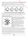
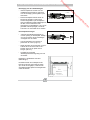
Adjusting the reduced flame position
The flame length in the minimum position is adjusted with a flat screw located on the valve. For
easier reduced flame adjustment, it is advised to remove the control panel and microswitch during
adjustment.
To determine the minimum position, ignite the burners and leave them at minimum position. With
the help of a small screwdriver fasten or loosen the bypass screw around 90 angular degrees. When
the flame has a length of at least 4mm, the gas is well distributed. Make sure that the flame does
not die out when passing from the maximum position to the minimum position. Create an artificial
wind with your hand toward the flame is stable.
:
Figure 9
Injector
Spanner
Figure 11
Figure 12
Figure 10
Changing the gas inlet:
For some countries, the gas inlet type can be different for NG/LPG gases. In such a case, remove the
current connection components and nuts (if any) and connect the new gas supply accordingly. In all
conditions, all components used in gas connections should be approved by local and/or
international authorities.
Regularly check the expiry date of your gas pipe. When the expiry date is reached, it is necessary to
change the hose. These pipes are available on the market and must be consistent with current
standards. After changing the hose, you should check that there is no leakage by referring to the
information in the above paragraph: Connecting gas and checking leakage.
Downloaded from www.vandenborre.be

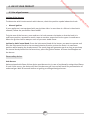
4. USE OF YOUR PRODUCT
14
4.1 Use of gas burners
•
:
Flame safety device:
Ignition of the burners
To determine which knob controls which burner, check the position symbol above the knob.
Manual Ignition
If your appliance is not equipped with any ignition aid or in case there is a failure in the electric
network, follow the procedures listed below
To ignite one of the burners, press and turn its knob counter-clockwise so that the knob is in
maximum position, approach a match, taper or another manual aid to its upper circumference.
Move the ignition source away as soon as you see a stable flame.
Ignition by Hob Control Knob: Press the hob control knob of the burner you want to operate and
turn the hob control knob in the counterclockwise direction so that the knob is in maximum
position while keeping the knob pressed. The spark plugs will generate sparks as long as you keep
the control knob pressed. At the same time, press the ignition button. A flame should appear on
the burner.
Hob Burners
Hobs equipped with flame failure device provide security in case of accidentally extinguished flame.
If such a case occurs, the device will block the burners gas lines and will avoid any accumulation of
unburned gas. Wait 90 seconds before re-igniting an extinguished gas burner.
Downloaded from www.vandenborre.be

4. USE OF YOUR PRODUCT
15
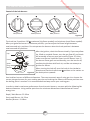
Control of the hob burners
The knob has 3 positions: Off , maximum (big flame symbol) and minimum (small flame symbol).
After you ignite the burner in maximum position; you can adjust the flame length between
maximum and min. positions. Do not operate the burners when the knob position is between
maximum and off positions.
After the ignition, check the flames visually. If you see yellow
tip, lifted or unstable flames; turn the gas flow off, and check
the assembly of burner caps and crowns (Figure 15). Also,
make sure that no liquid has flown into the burner cups. If
the burner flame goes out accidentally, turn the burner off,
ventilate the kitchen with fresh air, and do not attempt re-
ignition for 90 sec.
When turning the hob off, turn the knob in the clockwise
direction so that the knob shows position or the marker on
the knob points upwards.
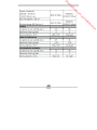
Your hob has burners of different diameters. The most economic way of using gas is to choose the
correct size gas burners for your cooking pan size and to bring the flame to minimum position once
the boiling point is reached. It is recommended to always cover your cooking pan.
In order to obtain maximum performance from the main burners, use pots with the following flat
bottom diameters. Using smaller pots than the minimum dimensions stated below will cause
energy loss.
Rapid / Wok Burner: 22-26cm
Semi-rapid Burner: 14-22cm
Auxiliary Burner: 12-18cm
MAX. position
OFF position
Figure 14
MODULATE
MIN. position
Figure 15
Cap
Crown
Spark
Plug
Burner
Thermocouple
Downloaded from www.vandenborre.be

4. USE OF YOUR PRODUCT
16
Make sure that the tips of the flames do not spread out of the outer circumference of the pan, as
this may also harm the plastic accessories around the pan (handles etc.)
When the burners are not in use for prolonged periods, always turn the main gas control valve off.
.
Figure 16
Warning:
When operating the hotplate for the first time or whenever the hotplate has not been used for a
prolonged time it is necessary to eliminate any humidity which may have accumulated around the
electrical elements of the plate by operating the hotplate on its lowest setting for about 20
minutes.
Use only flat pans and with a sufficiently thick base.
Never use a pan with a smaller diameter than of the hotplate.
Ensure that the base of the pan is dry before placing it on the hotplate. While the hotplate is in
operation, it is important to ensure that the pan is centered correctly above the hotplate.
•
•
•
!
• Never operate the hob without pans on the hotplate.
• The temperature of accessible parts may be high when the appliance is operating. So it is
imperative to keep children and animals out of the reach of the hotplate during and after the
operation.
• To ensure long life, the hotplate must be thoroughly cleaned with appropriate cleaning
products. To avoid rustiness and to keep them new it is recommended to rub the hotplate
lightly with tissue with a small amount of oil. Do not use a steam cleaner.
• After use, the hotplate remains very hot for a certain time, do not touch it and do not place any
object on top of the hotplate.
Downloaded from www.vandenborre.be

17
5. CLEANING AND MAINTENANCE
5.1 Cleaning
Make sure that all control switches are turned off before cleaning your appliance. Plug off the
appliance. Before using cleaning materials on your appliance, check that they are appropriate and
recommended by the manufacturer. As they may damage the surfaces, do not use caustic creams,
abrasive cleaning powders, thick wire wool or hard tools. In case the liquids that overflow around
your oven burn, the enameled parts may be damaged. Immediately clean the overflown liquids.
Cleaning of Your Hob
• Lift up the pan supports, caps and crowns of hob burners(Figure 15).
• Wipe and clean the back panel with a soapy cloth.
• Wash the caps and crowns of hob burners and rinse them. Do not leave them wet, immediately
dry them with paper cloth.
• After cleaning, make sure that you re-assemble the parts correctly.
• Do not clean any part of the hob with metal sponge. It causes the surface to be scratched.
• The pan support top surfaces may be scratched in time due to usage. These parts will not get
rusted and it is not a production fault.
• During cleaning of the hob plate, make sure that no water flows inside the burner caps, as this
may block the injectors.
Burner Caps:
Periodically, enameled pan support, enameled covers, burner heads must be washed with soapy
warm water rinsed and dried. After drying them thoroughly, replace them correctly.
Enamelled Parts:
In order to keep them a new, it is necessary to clean them frequently with mild warm soapy water
and then dry with cloth. Do not wash them while hot and never use abrasive powders or abrasive
cleaning materials. Do not leave vinegar, coffee, milk, salt, water, lemon, or tomato juice to remain
in contact with enameled parts for long periods of time.
Stainless Steel:
Stainless steel parts must be cleaned frequently with mildly warm soapy water and a soft sponge
and then dried with a soft cloth. Do not use abrasive powders or abrasive cleaning metarials. Do
not leave vinegar, coffee, milk, salt, water, lemon or tomato juice to remain in contact with stainless
steel parts for long periods of time.
Downloaded from www.vandenborre.be

Cleaning hotplates:
Clean the hotplates with a damp sponge and then dry them by turning them on for a few seconds.
To maintain their appearance, apply a small amount of oil on the surface of hotplates.
The hotplate trim rings can be cleaned with products intended for stainless steel. The rings can
become yellowed as a result of heating. This is normal.
If a hotplate is to be out of use for a long time, apply the special grease periodically.
5.2 Maintenance
Periodically check the gas connection pipe. Even if any simple abnormality is felt, inform the
technical service to have it changed. We recommend the gas connection parts to be changed once
a year. If any abnormality is felt while operating the control knobs of cooker, contact the authorized
service.
18
5. CLEANING AND MAINTENANCE
Downloaded from www.vandenborre.be

6.1 Basic troubleshooting before contacting service
If the hotplate does not operate :
• The hob may be plugged off, there has been a black out.
• Make sure that the hotplate is connected to the gas supply properly.
If the hotplate does not heat :
• Check that the control switch is set correctly.
The hob burners do not operate correctly :
• Check if the burner parts are correctly assembled(especially after cleaning).
• The gas supply pressure may be too low/high. Check that the butane/propane bottles are not
empty.
If the problem continues even after performing the above checks, please contact the customer
service.
6.2 Information related to transport
If you need any transport; keep the original case of product and carry it with its original case when
needed to be carried. Follow the transport signs on packaging. Tape the hob on upper parts, caps
and crowns and pan supports to the cooking panels.
If you do not have the original packaging; prepare a carriage box so that the appliance, especially
external surfaces (glass and painted surfaces) of oven is protected against external threats.
19
6. SERVICE AND TRANSPORT
Downloaded from www.vandenborre.be
La page est en cours de chargement...
La page est en cours de chargement...
La page est en cours de chargement...
La page est en cours de chargement...
La page est en cours de chargement...
La page est en cours de chargement...
La page est en cours de chargement...
La page est en cours de chargement...
La page est en cours de chargement...
La page est en cours de chargement...
La page est en cours de chargement...
La page est en cours de chargement...
La page est en cours de chargement...
La page est en cours de chargement...
La page est en cours de chargement...
La page est en cours de chargement...
La page est en cours de chargement...
La page est en cours de chargement...
La page est en cours de chargement...
La page est en cours de chargement...
La page est en cours de chargement...
La page est en cours de chargement...
La page est en cours de chargement...
La page est en cours de chargement...
La page est en cours de chargement...
La page est en cours de chargement...
La page est en cours de chargement...
La page est en cours de chargement...
La page est en cours de chargement...
La page est en cours de chargement...
La page est en cours de chargement...
La page est en cours de chargement...
La page est en cours de chargement...
La page est en cours de chargement...
La page est en cours de chargement...
La page est en cours de chargement...
La page est en cours de chargement...
La page est en cours de chargement...
La page est en cours de chargement...
La page est en cours de chargement...
La page est en cours de chargement...
La page est en cours de chargement...
La page est en cours de chargement...
La page est en cours de chargement...
La page est en cours de chargement...
La page est en cours de chargement...
La page est en cours de chargement...
La page est en cours de chargement...
La page est en cours de chargement...
La page est en cours de chargement...
La page est en cours de chargement...
La page est en cours de chargement...
-
 1
1
-
 2
2
-
 3
3
-
 4
4
-
 5
5
-
 6
6
-
 7
7
-
 8
8
-
 9
9
-
 10
10
-
 11
11
-
 12
12
-
 13
13
-
 14
14
-
 15
15
-
 16
16
-
 17
17
-
 18
18
-
 19
19
-
 20
20
-
 21
21
-
 22
22
-
 23
23
-
 24
24
-
 25
25
-
 26
26
-
 27
27
-
 28
28
-
 29
29
-
 30
30
-
 31
31
-
 32
32
-
 33
33
-
 34
34
-
 35
35
-
 36
36
-
 37
37
-
 38
38
-
 39
39
-
 40
40
-
 41
41
-
 42
42
-
 43
43
-
 44
44
-
 45
45
-
 46
46
-
 47
47
-
 48
48
-
 49
49
-
 50
50
-
 51
51
-
 52
52
-
 53
53
-
 54
54
-
 55
55
-
 56
56
-
 57
57
-
 58
58
-
 59
59
-
 60
60
-
 61
61
-
 62
62
-
 63
63
-
 64
64
-
 65
65
-
 66
66
-
 67
67
-
 68
68
-
 69
69
-
 70
70
-
 71
71
-
 72
72


Proline PGH4W-F Mode d'emploi
- Taper
- Mode d'emploi
- Ce manuel convient également à
dans d''autres langues
- English: Proline PGH4W-F Operating instructions
- Nederlands: Proline PGH4W-F Handleiding
Documents connexes
Autres documents
-
LG LF68V00S Le manuel du propriétaire
-
-
Whirlpool ACM 6601 G/WH Mode d'emploi
-
Valberg VAL CG 60 4CM NVT Le manuel du propriétaire
-
M-system MFTW95IXG60B Instructions And Advice For Installing, Using And Servicing
-
Miele KM2356-1 Le manuel du propriétaire
-
DeLonghi MEMV965TAX Le manuel du propriétaire
-
Brandt BIG60B Le manuel du propriétaire
-
-
Scholtes TV 751 GH Operating Instructions Manual