
pentair.com
23833A278 (02-13-20) ©2020 Pentair. All Rigths Reserved.
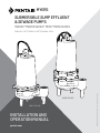
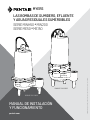
INSTALLATION AND
OPERATION MANUAL
SUBMERSIBLE SUMP EFFLUENT
& SEWAGE PUMPS
MWH50 MW200 SERIES ME50 ME150 SERIES
ENGLISH: 3-18 FRENCH: 21-36 ESPANOL: 39-54
MYER
S
DOUBLE SEAL PUMP
SINGLE SEAL PUMP

2 23822A278 (02-13-20)
TABLE OF CONTENTS:
ENGLISH
Safety Instructions ..................................................................................................................................................................................3
Description ..............................................................................................................................................................................................4
Installation ...............................................................................................................................................................................................5
Diagrams .............................................................................................................................................................................................6-8
Maintenance .......................................................................................................................................................................................9-10
Specications ........................................................................................................................................................................................11
Dimension Charts ..............................................................................................................................................................................12-13
Single Seal Pump Specications .......................................................................................................................................................14-15
Single Seal Pump Specications .......................................................................................................................................................16-17
Standard Limited Warranty ................................................................................................................................................................... 18
FRENCH
Instructions de sécurité ........................................................................................................................................................................ 21
Description...................................................................................... ................................................................................................. 22
Installation .............................................................................................................................................................................................23
Diagrammes .................................................................................................................................................................................... 24-26
Entretien ......................................................................................................................................................................................... 27-28
Spécications .......................................................................................................................................................................................29
Tableaux de dimensions ...................................................................................................................................................................30-31
Spécications pour les pompes à joint simple ................................................................................................................................. 32-33
Spécications pour les pompes à joint simple ................................................................................................................................. 34-35
Garantie limitée standard ......................................................................................................................................................................36
SPANISH
Instrucciones de seguridad ...................................................................................................................................................................39
Descripción .......................................................................................................................................................................................... 40
instalación ............................................................................................................................................................................................. 41
Diagramas .......................................................................................................................................................................................42-44
Mantenimiento .................................................................................................................................................................................45-46
Especicaciones ...................................................................................................................................................................................47
Tablas de dimensiones ....................................................................................................................................................................48-49
Especicaciones de bomba de sello único .......................................................................................................................................50-51
Especicaciones de bomba de sello doble ...................................................................................................................................... 52-53
Garantía limitada estándar ....................................................................................................................................................................54

3
23822A278 (02-13-20)
IMPORTANT SAFETY INSTRUCTIONS
SAVE THESE INSTRUCTIONS - This manual contains important
instructions that should be followed during installation,
operation, and maintenance of the product. Save this manual
for future reference.
This is the safety alert symbol. When you see this symbol on
your pump or in this manual, look for one of the following signal
words and be alert to the potential for personal injury!
indicates a hazard which, if not avoided, will result in
death or serious injury.
indicates a hazard which, if not avoided, could result
in death or serious injury.
indicates a hazard which, if not avoided, could result
in minor or moderate injury.
NOTICE
addresses practices not related to personalinjury.
CALIFORNIA PROPOSITION 65 WARNING
This product and related accessories contain
chemicals known to the State of California to cause cancer,
birth defects or other reproductive harm.
ELECTRICAL RISKS
Pumps with a single seal are supplied with a grounding
conductor and grounding-type attachment plug on the power
cord. To reduce the risk of electric shock:
Be certain that it is connected only to a properly grounded,
grounding-type receptacle.
DO NOT cut off ground pin or use an adapter fitting.
DO NOT use an extension cord with this pump.
Entire plug may be cut off if a control panel is used.
Wh
en wiring this pump follow all local electrical and safety
codes and ordinances as well as the most recent National
Electric Code (NEC-ANSI/NFPA 70).
All pumps have a GROUND WIRE that is connected to a screw
in the metal motor housing. This wire goes to the receptacle
or control box which must be connected to a good outside
GROUND such as a metal water pipe or GROUND STAKE driven
at least 8 feet into theground.
WHEN OVERLOAD CURRENT PROTECTION IS PROVIDED BY
INSTALLER:
USE WITH APPROVED MOTOR CONTROL THAT MATCHES
MOTOR INPUT IN FULL LOAD AMPERES WITH OVERLOAD
ELEMENT(S) SELECTED OR ADJUSTED IN ACCORDANCE WITH
CONTROL INSTRUCTIONS.
WHEN MOTOR HAS BUILT-IN OVERLOAD PROTECTION:
USE WITH APPROVED MOTOR CONTROL THAT MATCHES
MOTOR INPUT IN FULL LOADAMPERES.
SAFETY INSTRUCTIONS

4 23822A278 (02-13-20)
DESCRIPTION
Myers ME and MW series pumps are available in both a single
seal as well as a double seal design with leak detector. The
ME50-ME150 models are designed for effluent dosing, Septic
Tank Effluent Pumping (S.T.E.P.) or normal sump and general
dewatering applications where higher pressure is required.
These units are designed to handle ¾” spherical solids.
The MWH50-MW200 models are designed for raw sewage
applications and can pass 2” spherical solids. These units can
also be used for sump and general dewatering applications
where larger solids capabilities are required.
When used in effluent dosing or S.T.E.P. applications, the pump
must be installed in a separate tank or compartment at the
discharger side of the septic tank. Never install pump in tank
where sludgecollects.
These pumps are available in single phase and three phase,
and either in single seal or double seal with seal leak detector.
All three phase units, all double seal units and all duplex
installations must be used with a control box. All power cords
and seal leak detector cords are 20 feet long.
The ME model impellers are enclosed two vane type to handle
¾” spherical solids and are available made of engineered
thermoplastic or optional naval bronze. All pumps have a 2” NPT
discharge tapping.
The MW model impellers are enclosed two vane non-clog
style, designed to handle 2” spherical solids. The MW pumps
are available with standard cast iron or optional naval bronze
impellers.
These pumps are NOT for use in swimming pools orfountains.
AIR LOCKING
A sump pump is said to be air locked if water traps air in the
pump and it cannot get out, thus preventing the pump from
operating.
In installation of this type a 1/8” hole should be drilled in the
discharge pipe just above the pump discharge and a check valve
should be installed 12 to 18 inches above pump discharge. Do not
put check valve directly into pump discharge opening - follow
local code.
PACKAGING
Each pump is packaged separately in a carton marked with a
catalog number and the Myers engineering number.
LEVEL CONTROLS
All pumps must use sealed level control switches for automatic
operation. MLC and MFLC controls have sealed switches that
are 1 HP rated at 230 volts. ALC and AWS-1 controls have sealed
mechanical switches that are rated 2 HP at 230 volts.Simplex
single phase pumps can be made automatic by attaching MFLC
or MFS controls to the pump. These switches have a fixed draw
off level of 8 to 10 inches and can be used up to 1 HP. For higher
horsepower ratings two mercury switches (or SMNO) controls
with a magnetic starter can be used. Simplex systems may
also use on/off pilot mercury control switches (when permitted
by code) with control box and magnetic starter. The ALC and
AWS-1 controls can be used for simplex single phase pumps with
ratings up to 2 HP. All duplex systems must use pilot mercury
control switches with control box and magnetic starters.
Plug-in cords can be used on all the single phase pumps with
a single seal (does not have a seal leak detector). This cord
has a GROUND pin that plugs into a grounded receptacle. The
grounded receptacle cannot be used in the wet sump or basin
due to DANGER of current leakage. Sealed junction boxes must
be used in wet sumps or basins to make connections to motor
cord. The AWS-1 control also acts as a sealed junction box for
connecting power cord to pump cord.
DOUBLE SEAL PUMPS
All pumps in this series “ME—D” or “MW—D” have two seals with
an oil chamber between the seals so that the seal faces of
both the lower and upper seals are oil lubricated for longer life
and greater protection against water leaking into the motor
windings. These double seal units are all made with a seal leak
detector.
The leak detector in the oil seal chamber detects any water
leakage into the chamber and turns on a red signal light in
the control panel. Pumps should be removed from the sump
and seals replaced after the seal light shows in the panel.
Control panels must be used for pumps having the seal leak
detectors, and seal leak detectors must be wired as illustrated
in theseinstructions.
D ESIGN OF PRESSURE SEWER SYSTEMS
MYERS has available complete computer SOFTWARE for
designing PRESSURE SEWER SYSTEMS. This gives pipe sizes to
use and gives exact flow from any pump or group of pumps in the
system when operating simultaneously. This design DISK for IBM
or COMPATIBLE computers is available to engineers onrequest.
DESCRIPTION

5
23822A278 (02-13-20)
MOTOR TYPE
Motors are ¾ frame, 1/2 – 2HP single or three phase, 60 Hertz,
3450 R.P.M. with class B insulation. All single phase motors are
permanent split-capacitor (PSC) type with built-in on-winding
overload protection and do not require a start switch or start
relay. The three phase pump motors require a magnetic starter
with 3 leg overload protection. All motors have upper and lower
ball bearings and all are oil-cooled and lubricated.
Breathing hazard. Basin or tank must be vented in
accordance with local plumbing codes. These pumps are not
designed for and CANNOT be installed in locations classified as
hazardous in accordance with the National Electric Code ANSI/
NFPA 70.
Never enter pump chamber after sewage or effluent
has been in basin. Sewage water can give off methane,
hydrogen sulfide and other gases which are highly
poisonous.
Myers recommends installing ME series effluent pumps with
a quick removal system. The quick removal system may be a
union or quick-release coupling if the pipe or discharge hose
is within reach from the surface, or a rail system type quick
disconnect on deeper installations. See installation drawings for
suggestedinstallation.
The dosing tank or pumping chamber must be constructed
of corrosion resistant materials and must be capable of
withstanding all anticipated internal and external loads. It also
must not allow infiltration or exfiltration. The tank must have
provisions for anti-buoyancy. Access holes or covers must be
of adequate size and be accessible from the surface to allow
for installation and maintenance of the system. Access covers
must be lockable or heavy enough to prevent easy access
by unauthorized personnel. The pumping chamber holding
capacity should be selected to allow for emergency conditions.
The discharge pipe must be the same size as the pump
discharge (2 inches) or larger. In order to insure sufficient fluid
velocity to prevent any residual solids from collecting in the
discharge pipe, it is recommended that a minimum flow of 2 feet
per second be maintained. (21 GPM through 2” pipe and 46 GPM
through 3” pipe). It is recommended that PVC or equal pipe is
used for corrosion resistance.
A full flow (ball or gate) shut off valve must be installed to
prevent back flow of effluent if the pump must be removed for
service. A check valve must be installed on pressure sewer
systems and on other systems where conditions allow to
prevent backflow and to reduce wear on the pump system.
A high water alarm must be installed on a separate circuit from
the pump circuit. The alarm should have the ability to be tested
for proper operation.
S PECIAL INSTRUCTIONS FOR THREE PHASE PUMPS
1. Myers recommends three phase pumps to be installed by
qualified personnel.
2. Risk of electric shock. Do not remove cord and
strain relief. Do not connect conduit topump.
3. Three phase pumps are always installed with control boxes
having magnetic starters with 3 leg overload protection. DO
NOT TRY TO RUN THREE PHASE PUMPS DIRECTLY ACROSS
THE LINE.
4. To Connect Pump: Run wire from pump to the bottom
of control box or appropriate junction box suitable for
enclosing splice connections. A hole must be cut into the
control box for the wires. With power to control box off,
connect green (ground) line to ground lug. Connect black
(power) wires to power lead terminals.Note: for a typical CE
style control box, these terminals are marked M1, M2 and
M3. Make sure that all wires are inside control box and not in
a position to be pinched or shorted when the door is closed.
INSTALLATION

6 23822A278 (02-13-20)
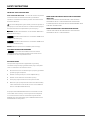
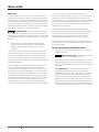
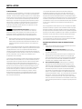
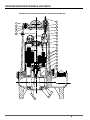
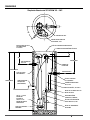
30” Diameter Simplex ME/MW 1/2 – 2 HP
RAIL SUPPORT
JUNCTION BOX
STRUCT. PLASTIC
As Req’d.
AS REQ’D.
CONTROL MOUNTING
BRACKET, SST
45º
AS
REQ’D.
30” DIA. BASIN COVER
VALVE EXTENSION HANDLE
18
1-1/2” CONDUIT
REQ’D.
30” DIA.
CONCRETE WELL
INLET HUB
(AS REQ’D.)
PUMP “OFF” LEVEL
ME 1/2 – 1-1/2 HP
EFFLUENT PUMP
MW 1/2 – 2 HP
SEWAGE PUMP
LIFT-OUT ROPE
2” DISCHARGE
2” GATE VALVE, BRASS
2” DISCHARGE PIPE, PVC
GUIDE RAILS, 3/4” GALV.
HIGH WATER “ALARM” LEVEL
PITLESS DISCONNECT, BRAS
S
2” SWING CHECK VALVE, PVC
PUMP “ON” LEVEL
6
DIAGRAMS

7
23822A278 (02-13-20)
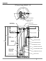
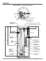
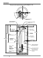
30” Diameter Simplex Union System ME/MW 1/ - 2 HP
CONTROL MOUNTING
BRACKET, SST
45º
JUNCTION BOX
STRUCT. PLASTIC
AS REQ’D.
AS REQ’D.
30” DIA. BASIN COVER
2” UNION, PVC
18
1-1/2” CONDUIT
REQ’D.
30” DIA.
CONCRETE WELL
INLET HUB
(AS REQ’D.)
PUMP “OFF” LEVEL
ME 1/2 – 1-1/2 HP
EFFLUENT PUMP
MW 1/2 – 2 HP
SEWAGE PUMP
LIFT-OUT ROPE
2” DISCHARGE
2” GATE VALVE,
BRASS
2” DISCHARGE
PIPE, PVC
HIGH WATER “ALARM” LEVEL
2” SWING CHECK VALVE, PVC
PUMP “ON” LEVEL
6
AS REQ’D.
DIAGRAMS

8 23822A278 (02-13-20)
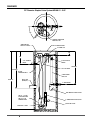
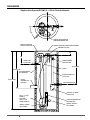
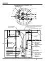
48” Diameter Duplex ME/MW 1/2 – 2 HP
RAIL SUPPORT
CONTROL MOUNTING
BRACKET, SST
45º
71/8
71/8
JUNCTION BOX
STRUCT. PLASTIC
AS REQ’D.
AS REQ’D.
AS REQ’
D.
48” BASIN COVER W/HINGED HATCH
& LOCK HASP EPOXY COATED 1/4” STEEL
VALVE EXTENSION HANDLE
18
2” CONDUIT
REQ’D.
48” DIA.
CONCRETE WELL
INLET HUB
(AS REQ’D.)
PUMP “OFF” LEVEL ME 1/2 – 1-1/2 HP
EFFLUENT PUMP
MW 1/2 – 2 HP
SEWAGE PUMP
LIFT-OUT ROPE
2” DISCHARGE
2” GATE VALVE, BRASS
2” DISCHARGE PIPE, PVC
GUIDE RAILS, 3/4” GALV.
PITLESS DISCONNECT
, BRASS
2” SWING CHECK VALVE, PVC
6
HIGHWATER “ALARM” LEVEL
LAG PUMP “ON” LEVEL
LEAD PUMP “ON” LEVEL
DIAGRAMS

9
23822A278 (02-13-20)
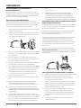
BEFORE DISMANTLING PUMP FOR REPLACEMENT OF PARTS
Clean pump thoroughly. Knock off all scale and deposits. Use
sandblast if possible. Submerge complete unit in dilute bleach
solution for one hour beforedisassembly.
TO REPLACE CAPACITORS ONLY
All of the single phase motors are of the permanent split
capacitor type and have no relays or starting switch. They have
only a starting capacitor that is in the circuit for both starting
and running conditions.
1. Remove oil fill plug near the top of the motor and pour the oil
out.
2. Loosen the pug nuts around the cords until they are loose
enough to push the cords down inside of the motor housing.
3. Remove the four bolts from the motor housing and bump the
housing with a plastic hammer to loosen. Lay the pump on
its side.
4. Remove the housing carefully to be sure that enough cord is
pushed into the housing to create no tension on the cords.
5. Slide motor housing up far enough to expose the capacitor
and to be able to lay the housing down.
6. Disconnect wiring from capacitor and loosen capacitor
clamp and slide out capacitor. Replace with new capacitor,
tighten and re-connect. Wiring diagram is given in these
instructions.
7. Check all wiring connectors to be sure they aresecure.
8. Be sure tetraseal gasket is in place.
9. Slide motor housing back onto pump while pulling the cords
out slowly. Assemble the motor housing with the four bolts.
10. Re-assemble cord nuts. Be sure washers are seated and
cords are pulled up to stop against the washers. Tighten
nuts securely.
11. Put pump upright and refill motor with refined paraffinic
transformer oil, ¹Shellflex™ 2210 or equivalent. DO NOT
OVER FILL WITH OIL. With pump upright fill oil to bottom of
oil fill tapping. Replace oil fill plug
¹ Shell Oil Company, Texas
12. Be sure pump turns freely before connecting to power. Turn
pump on side and turn impeller, using screwdriver in slotted
shaft. Plug pump into receptacle to test operation. Pump
must run quiet and free of vibration.
TO REPLACE POWER CORD AND/OR SEAL LEAK
DETECTOR CORD
Remove motor housing as described above. Disconnect the
push-together terminals and remove the ground screw from the
power cord if beingreplaced.
Completely unscrew cord bushing to be replaced and remove
cord assembly from housing. Be sure remaining terminals are
secure on the wires.
Replace with proper cord with fittings. Push cord into the motor
housing far enough to make proper connections. Reconnect
ground wire if replacing power cord and securely connect the
wires correctly. See wiring diagram in these instructions.
Assemble cords and motor housing as described in Capacitor
Replacement. Fill with oil as noted and be sure pump turns
freely before connecting topower.
T O REPLACE MOTOR STATOR AND SHELL
1. Remove motor housing as described above.
2. Disconnect all leads from power and seal leak cords and
ground wire and set pump upright.
3. Loosen the four long screw holding the motor and remove
slowly. If unit has seal leak probes, be sure to feed the wires
through the slots as the motor is being removed.
4. Either remove previous capacitor and clamp from old motor
and assemble onto new stator and shell or replace with a
new capacitor and assemble the two capacitor leads per
wiring diagram.
5. Position bearing spring washer on top of upper ball bearing.
6. Tighten terminal screws of seal leak probes and feed wires
through the motor slots.
7. Position the “stator with shell” into place and line up screws
with the bosses and tighten the (4) long screws. Extend
probe wires out through the slots. Lay unit down in line with
motor housing.
8. Be sure pump turns freely with screwdriver in impeller end
of shaft.
9. Reconnect all terminals securely per wiringdiagram.
10. Be sure tetraseal gasket is in place.
11. Reassemble motor housing and fill with oil as noted above in
capacitor replacement.
NOTICE On three phase motors always check unit for proper
rotation. With pump on its side apply power by turning on, then
off, quickly. Impeller must turn counter-clockwise when looking
into the impeller inlet. If not, interchange any two leads in the
control box.
MAINTENANCE

10 23822A278 (02-13-20)
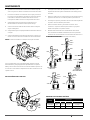
3 PHASE DUAL VOLTAGE WINDING
Voltage Leads
Black White Red Together
208 & 230 1 & 7 2 & 8 3 & 9 4 & 5 & 6
460 1 2 3 4 & 7, 5 & 8, 6 & 9
GREEN
BLACK
WHITE
BLACK
WHITE
BROWN
GROUND
115V ., 208V. OR 230V.
1 PHASE, P.S.C.
GREEN
BLACK
WHITE
GROUND
RED
BLACK
575V. - 3 PHASE
BLACK
YELLOW
SEAL LEAK
DETECTOR
TYP. FOR 1 & 3Ø
(DOUBLE SEAL ON LY )
GREEN
BLACK
WHITE
GROUND
RED
208/230V. - 3 PHAS E460V. - 3 PHAS E
GREEN
BLACK
WHITE
GROUND
RED
Lorem ipsum
GREEN
BLACK
WHITE
BLACK
WHITE
BROWN
GROUND
115V ., 208V. OR 230V.
1 PHASE, P.S.C.
GREEN
BLACK
WHITE
GROUND
RED
BLACK
575V. - 3 PHASE
BLACK
YELLOW
SEAL LEAK
DETECTOR
TYP. FOR 1 & 3Ø
(DOUBLE SEAL ON LY )
GREEN
BLACK
WHITE
GROUND
RED
208/230V. - 3 PHAS E460V. - 3 PHAS E
GREEN
BLACK
WHITE
GROUND
RED
Lorem ipsum
SHAFT SEAL REPLACEMENT
1. Remove plugs in motor housing and in seal housing (for
double seal units) and drain oil.
2. Remove four bolts holding the volute case and bump with a
plastic hammer to loosen and removecase.
3. Hold impeller and unscrew impeller locking screw. Turn
counterclockwise to loosen.
4. Pry off seal bellows and ceramic seat. Break seats if
necessary to get out since they must be replaced with new
parts.
5. NEVER USE OLD SEAL PARTS - USE ONLY COMPLETELY
NEW SEALS. (Do not use seal spring retainer plate on single
seal pump or lower seal of double seal pump.)
6. For single seal pumps or if only replacing the lower seal
of a double seal pump, it is not necessary to disassemble
further. On a double seal pump, it is not necessary to drain
oil out of the motor housing, just the seal housing.
7. On a double seal pump, to remove the upper seal, remove
four bolts holding the bottom plate and remove bottom
plate.
8. Remove snap ring with snap ring pliers. Pry off upper seal
bellows and ceramic seat.
9. If no water has entered motor housing (check winding with
ohmmeter or megger) wipe seal chambers thoroughly and
replace seals. (Use seal retainer plate on upper seal only; do
not use on lower seal.) Clean seal faces and use light on face
before installing bellows part of seal.
10. Check HUVA cup seal in volute case inlet. If worn,replace.
11. Be sure tetraseal gasket is in position (replace if worn) and
reassemble.
12. Replace oil in motor housing and seal chamber. Use only
Myers submersible oil.
13. Be sure pump turns freely before connecting to power. After
connecting, check for proper rotation noted under
Stator Replacement.
WIRING DIAGRAM
MAINTENANCE

11
23822A278 (02-13-20)
Relay: SSAC Inc. #LLC44A5A
Socket: Standard 8-pin plug-in type
If Myers panel is used see below.
Pumps: ME50D-11,
ME75D-11
Required Panel:
CMEP(SL)-11S, -11SW,-11D, or -11DW
Pumps: ME50D-01, ME50D-21,
ME75D-01, ME75D-21,
ME100D-01, ME100D-21,
ME150D-01, ME150D-21,
MWH50D-01, MWH50D-21,
MW100D-01, MW100D-21,
MW150D-01, MW150D-21,
MW200D-01, MW200D-21
Required Panel:
CMEP(SL)-21S, -21SW,-21D, or -21DW
Pumps: ME50D-03, ME50D-23,
ME75D-03, ME75D-23,
ME100D-03, ME100D-23,
ME150D-03, ME150D-23,
MWH50D-03, MWH50D-23,
MW100D-03, MW100D-23,
MW150D-03, MW150D-23,
MW200D-03, MW200D-23
Required Panel:
CMEP(SL)-23S, -23SW,-23D, or -23DW
Pumps: ME50D-43,
ME75D-43,
ME100D-43,
ME150D-43,
MWH50D-43,
MW100D-43,
MW150D-43,
MW200D-43
Required Panel:
CMEP(SL)-43S, -43SW,-43D, or -43DW
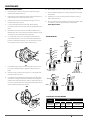
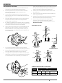
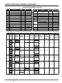
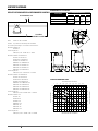
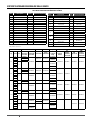
ME SERIES DIMENSIONS
Model Series Inches (milimeters)
A B C F
ME50S 16.8 (427) 4.09
(104)
1.03
(26)
12.13
(308)
ME50D 18.6 (472)
ME75S, ME100S, ME150S 16.8 (427) 4.0
(102)
1.06
(27)
12.5
(318))
ME75D, ME100D, ME150D 18.6 (472)
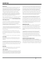
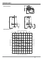
ME PERFORMANCE CURVE
INCOMING 115V, 1 PH
TO AUDIBLE OR
VISUAL ALARM
TO SEAL LEAK
PROBES
27
56
13
RI
RI
11.47
(291)5.12
(130)
9.63
(245)
2” NPT
Discharge
F
A
C
B
A
C
B
CAPACITY LITERS PER MINUTE
CAPACITY GALLONS PER MINUTE
TOTAL HEAD IN FEET
TOTAL HEAD IN METERS
0 50 100 150 200 250 300 350 400 450
0 10 20 30 40 50 60 70 80 90 100 110 120 130
100
90
80
70
60
50
40
30
20
10
0
28
24
20
16
12
8
4
0
ME 150
ME 100
ME 75
ME 50
M OISTURE SENSOR SEAL PROBE CIRCUIT
SPECIFICATIONS

12 23822A278 (02-13-20)
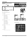
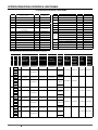
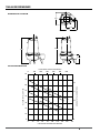
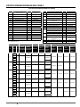
MW PERFORMANCE CURVE
MW200
MW150
MW100
MWH50
CAPACITY LITERS PER MINUTE
CAPACITY GALLONS PER MINUTE
TOTAL HEAD IN FEET
TOTAL HEAD IN METERS
0 100 200 300 400 500 600
0 20 40 60 80 100 120 140 160 180
80
70
60
50
40
30
20
10
0
20
15
10
5
0
DIMENSION CHARTS
MW SERIES DIMENSIONS

13
23822A278 (02-13-20)
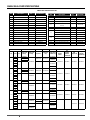
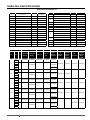
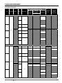
MOTOR DATA CHART
H.P. Speed Volts Phase Stack Height
Winding Resistance In Ohms
Max. Amps Locked Rotor
Amps
Main
Black To
White
Start - 1Ø
Brn. To Brn. Or
Purple White To Red
Black To Red - 3Ø
ME Series
1/2
3450
115
1
1-5/8
.9/.8 14.7
-
12.1 29.6
208 6.7 16.5
230 9.8 19.7 6.0 15.0
208/230
3
11.3 11.3 11.3 3.5/3.2 12.8
460 45.4 45.4 45.4 1.6 6.4
575 71.0 71.0 71.0 1.3 5.1
3/4
115 12-1/4 .85 4.9 -13.8 30.4
208/230 4.5 12.0 7.6/6.9 16.2
208/230
3 2
7.6 7.6 7.6 5.2/4.7 20.2
460 30.1 30.1 30.1 2.3 10.1
575 47.0 47.0 47.0 1.9 8.1
1
208 12-3/4 -10.3 21.0
230 3.0/2.6 16/14 9.3 19.0
208/230
32-1/2
5.3 5.3 5.3 6.6/6.0 29.0
460 21.2 21.2 21.2 3.0 14.5
575 33.1 33.1 33.1 2.4 11.6
1-1/2
208 1
2-3/4
-14.1
230 2.4 12.0 12.8 23.0
208/230
3
4.5 4.5 4.5 8.8/8.0 30.0
460 16.0 16.0 16.0 4.0 15.0
575 25.0 25.0 25.0 3.2 12.0
MW Series
1/2
3450
208 12-1/4 4.5 12.0 -7.6 16.2
230 6.9
208
3 2
7.6 7.6 7.6 5.2 20.2
230 4.7
460 30.1 30.1 30.1 2.3 10.1
575 47.0 47.0 47.0 1.9 8.1
1
208 12-3/4 2.2 11.5 -10.3 21.0
230 2.8 15.0 9.3 19.0
208
32-1/2
5.3 5.3 5.3 6.6 29.0
230 6.0
460 21.2 21.2 21.2 3.0 14.5
575 33.1 33.1 33.1 2.4 11.6
1-1/2
208 1
2-3/4
2.1 9.3 -14.8 39.9
230 1.6 7.4 12.8 33.4
208
3
4.5 4.5 4.5 7.7 30.0
230 7.0
460 18.0 18.0 18.0 3.5 15.0
575 28.0 28.0 28.0 2.8 12.0
2
208 12.1 9.3 -15.3 39.9
230 1.6 7.4 13.1 33.4
208
3
4.5 4.5 4.5 8.5 30.0
230 4.5 4.5 7.7
460 18.0 18.0 18.0 3.9 15.0
575 28.0 28.0 28.0 3.1 12.0
DIMENSION CHARTS

14 23822A278 (02-13-20)
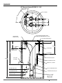
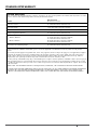
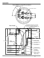
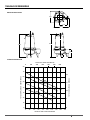
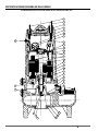
TYPICAL SECTION DRAWING FOR ME/MW50-200 SINGLE SEAL PUMPS
OIL LEVEL
1
2
3
4
5
6
7
8
9
10
11
12
13
14
15
16
17
18
19
20
21
22
2” NPT
23
24
25
26
27
28
SINGLE SEAL PUMP SPECIFICATIONS

15
23822A278 (02-13-20)
SINGLE SEAL REPAIR PARTS LIST
Ref. Description Qty. Part Numbers
1Nut, cord plug, solid 1 25341A002
2Washer, 1/32” Thk. 1 05030A234
3Gasket, Rubber 1 05014A193
4Washer, 3/32” Thk. 1 05030A235
5Plug, 1/4” pipe 1 05022A009
6Cord, Power 1See Chart
7Screw, drive 2 05160A004
8Name Plate 1N/A
9Housing, Motor 1 25327D000
10 Capacitor (1Ph only) 1See Chart
11 Clip, capacitor (1 Ph only) 1See Chart
12 Oil, Transformer .8-1 gal 11009A006
12A Connectors (3 Ph only) 3-6 15781A001
13 Washer, bearing 1 19331A005
14 Bearing, ball, upper 1 08565A013
15 Screw, st, #10 x 3/8 2 09822A032
Unit manufactured prior to Aug-2007 contact factory for repair parts.
Ref. Description Qty. Part Number
16 & 17 Stator, Rotor shaft with shell 1 See Chart
18 Bearing, ball, lower 108565A022
19 Seal, shaft 1 25370A000
20 Plate, brg & seal 1 25367D000
21 Gasket, tetraseal, 7x6-
3/4x1/8 105014A181
22 Screw, cap, 5/16 x 1-1/4 8 19100A012
23 Impeller 1See Chart
24
Case, volute (ME50) 1 25357D000
Case, volute (ME75-150) 1 25331D000
Case, volute (MWH5-200) 1 26057D000
25 Cup, U, HUVA (ME50-150) 1 22835A005
Cup, U, HUVA (MWH50-200) 1 22835A009
26 Washer, Impeller Retainer 105030A242
27 Screw, Machine #10 x 3/8 1 06106A042
28 Sealant 114550A001
Item Number 6 10 11 16 & 17 23
HP Volts PH Power Cord
W/Plug
Power Cord
No Plug Capacitor Capacitor
Clip
Stator Rotor
& Shaft Ass’y
ME
Impeller
Plastic
ME
Impeller
Optional
Naval Bronze
MW
Impeller DI
MWH Impeller
Optional
Naval Bronze
1/2
115
1
25338B004
25338B006
23839A000 20333A006
25484D100
25333B025 25348B121 26029B013 26029B113
208 25484D101
230 25338B005
208
325484D102230
460
575 25484D103
3/4
115 25338B000
25338B002 23839A000 20333A006
25484D100
25348B020 25348B120
208 25484D101
230 25338B001
208
3 25338B003 25484D102230
460
575 25484D103
1
208 1 25338A002 23838A000 20333A004 25484D104
25348B010 25348B110 26029B012 26029B112
230 25338B001 25484D105
208
3 25338B003 25484D106230
460
575 25484D107
1-1/2
208 1 25338B002 23838A000 20333A004 25484D104
25348B000 25348B100 26029B011 26029B111
230 25338B001 25484D105
208
3 25338B003 25484D106
230
460
575
2
208 1 25338B009 23839A000 20333A006 25484D108
26029B000 26029B100
230 26520A000 25484D109
208
3
25338B008 25484D110
230 25484D111
460 25338B003
575 25484D112
SINGLE SEAL PUMP SPECIFICATIONS

16 23822A278 (02-13-20)
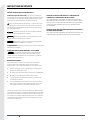
TYPICAL SECTION DRAWING FOR ME/MW50-200 DOUBLE SEAL PUMPS
28
29
30
25
26
27
9
21
8
1
2
3
4
5
6
7
9
10
11
12
13
14
15
16
17
18
19
20
21
22
23
24
2” NPT
DOUBLE SEAL PUMP SPECIFICATIONS

17
23822A278 (02-13-20)
DOUBLE SEAL REPAIR PARTS LIST
Ref. Description Qty. Part Number
1Cord, Sensor 125339B000
2Cord, Power 1See Chart
3Screw, drive 205160A004
4Name Plate 1N/A
5Housing, Motor 125327D000
6 Capacitor (1Ph only) 1 See Chart
7 Clip, capacitor (1 Ph only) 1 See Chart
8Plug, 1/4” pipe 105022A009
9Oil, Transformer 1.12 gal 11009A006
9A Connectors (3 Ph only) 3-6 15781A001
10 Screw, st, #10 x 3/8 2 09822A032
11 Washer, bearing 119331A005
12 Bearing, ball, upper 108565A013
13 & 14 Stator, Rotor shaft with shell 1 See Chart
15 Wire, electrode 221792A004
16 Screw, #6 x 1/4 2 05434A025
17 Seal Probe 225343A000
Unit manufactured prior to Aug-2007 contact factory for repair parts.
Ref. Description Qty. Part Number
18 Bearing, ball, lower 108565A022
19 Seal, shaft 1 25370A000
20 Ring, retaining 212558A021
Ring, retaining 112558A033
21 Gasket, tetraseal, 7x6-3/4x1/8 205014A181
22 Housing seal 125369D000
23 Plate, bottom 125368D000
24 Screw, cap 5/16 x 1-1/4 12 19100A012
25 Impeller 1See Chart
26
Case, volute (ME50) 1 25357D000
Case, volute (ME75-150) 1 25331D000
Case, volute (MWH50-200) 1 26057D000
27 Cup, U, HUVA (ME50-150) 1 22835A005
Cup, U, HUVA (MWH50-200) 1 22835A009
28 Washer, Impeller Retainer 105030A242
29 Screw, Machine #10 x 3/8 1 06106A042
30 Sealant 114550A001
Item Number 2 6 7 13 & 14 25
HP Volts PH Power Cord
W/Plug
Power Cord
No Plug Capacitor Capacitor
Clip
Stator
Rotor &
Shaft Ass’y
ME
Impeller
Plastic
ME
Impeller
Optional
Naval
Bronze
MW
Impeller DI
MWH
Impeller
Optional
Naval
Bronze
1/2
208 125338B005 25338B006 23839A000 20333A006 25484D201
25333B025 25348B121 26029B013 26029B113
230
208
325338B003 25484D202230
460
575 25484D203
3/4
208 125338B001 25338B002 23839A000 20333A006 25484D201
25348B020 25348B120
230
208
325338B003 25484D202230
460
575 25484D203
1
208 125338B001 25338B002 23838A000 20333A004 25484D205
25348B010 25348B110 26029B012 26029B112
230
208
325338B003 25484D206230
460
575 25484D207
1-1/2
208 125338B001 25338B002 23838A000 20333A004 25484D205
25348B000 25348B100 26029B011 26029B111
230
208
325338B003 25484D206230
460
575 25484D207
2
208 125338B001 25338B002 26520A002 25484D209
26029B000 26029B100
230
208
325338B003 25484D211230
460
575 25484D212
DOUBLE SEAL PUMP SPECIFICATIONS

18 23822A278 (02-13-20)
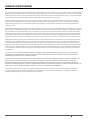
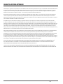
Limited Warranty
Myers® warrants to the original consumer purchaser (“Purchaser” or “You”) of the products listed below, that they will be free from
defects in material and workmanship for the Warranty Period shown below.
Product Warranty Period
whichever occurs first:
Jet pumps, small centrifugal pumps, submersible pumps and
relatedaccessories 12 months from date of original installation,
or 18 months from date of manufacture
Fibrewound Tanks 5 years from date of original installation
Steel Pressure Tanks 5 years from date of original installation
Sump/Sewage/Effluent Products 12 months from date of original installation,
or 36 months from date of manufacture
Battery Backup Units
MBSP-2, MBSP-2C
MBSP-3, MBSP-3C
12 months from date of original installation,
or 18 months from date of manufacture
24 months from date of original installation,
or 30 months from date of manufacture
Wastewater Solids Handling Pumps 12 months from date of shipment from factory
or 18 months from date of manufacture
Our warranty applies only where such products are used in compliance with the requirements of the applicable product catalog
and/or manuals. For additional information, please refer to the applicable standard limited warranty featured in the product
manual.
Our warranty will not apply to any product that, in our sole judgement, has been subject to negligence, misapplication, improper
installation, or improper maintenance. Without limiting the foregoing, operating a three phase motor with single phase power
through a phase converter will void the warranty. Note also that three phase motors must be protected by three-leg, ambient
compensated, extra-quick trip overload relays of the recommended size or the warranty is void.
Your only remedy, and MYERS’s only duty, is that MYERS repair or replace defective products (at MYERS’s choice). You must pay all
labor and shipping charges associated with this warranty and must request warranty service through the installing dealer as soon
as a problem is discovered. No request for service will be accepted if received after the Warranty Period has expired. This warranty
is not transferable.
MYERS SHALL NOT BE LIABLE FOR ANY CONSEQUENTIAL, INCIDENTAL, OR CONTINGENT DAMAGES WHATSOEVER.
THE FOREGOING LIMITED WARRANTIES ARE EXCLUSIVE AND IN LIEU OF ALL OTHER EXPRESS AND IMPLIED WARRANTIES,
INCLUDING BUT NOT LIMITED TO IMPLIED WARRANTIES OF MERCHANTABILITY AND FITNESS FOR A PARTICULAR
PURPOSE. THE FOREGOING LIMITED WARRANTIES SHALL NOT EXTEND BEYOND THE DURATION PROVIDED HEREIN.
Some states do not allow the exclusion or limitation of incidental or consequential damages or limitations on the duration of an
implied warranty, so the above limitations or exclusions may not apply to You. This warranty gives You specific legal rights and You
may also have other rights which vary from state to state.
This Limited Warranty is effective April 1, 2014 and replaces all undated warranties and warranties dated before April 1, 2014.
F.E. MYERS
293 Wright Street, Delavan, WI 53115
Phone: 888-987-8677 • Fax: 800-426-9446 • www.femyers.com
In Canada: 490 Pinebush Road, Unit 4, Cambridge, Ontario N1T 0A5
Phone: 800-363-7867 • Fax: 888-606-5484
STANDARD LIMITED WARRANTY

19
23822A278 (02-13-20)
NOTES

pentair.com
23833A278 (02-20-20) ©2020 Pentair. Tous droits réservés.
MANUEL D'INSTALLATION
ET D'UTILISATION
POMPES D'EFFLUENT ET
DE PUISARD SUBMERSIBLES
MWH50 MW200 SERIES
ME50 ME150 SERIES
MYER
S
POMPE À JOINT DOUBLE
POMPE À JOINT SIMPLE
La page est en cours de chargement...
La page est en cours de chargement...
La page est en cours de chargement...
La page est en cours de chargement...
La page est en cours de chargement...
La page est en cours de chargement...
La page est en cours de chargement...
La page est en cours de chargement...
La page est en cours de chargement...
La page est en cours de chargement...
La page est en cours de chargement...
La page est en cours de chargement...
La page est en cours de chargement...
La page est en cours de chargement...
La page est en cours de chargement...
La page est en cours de chargement...
La page est en cours de chargement...
La page est en cours de chargement...
La page est en cours de chargement...
La page est en cours de chargement...
La page est en cours de chargement...
La page est en cours de chargement...
La page est en cours de chargement...
La page est en cours de chargement...
La page est en cours de chargement...
La page est en cours de chargement...
La page est en cours de chargement...
La page est en cours de chargement...
La page est en cours de chargement...
La page est en cours de chargement...
La page est en cours de chargement...
La page est en cours de chargement...
La page est en cours de chargement...
La page est en cours de chargement...
La page est en cours de chargement...
La page est en cours de chargement...
-
 1
1
-
 2
2
-
 3
3
-
 4
4
-
 5
5
-
 6
6
-
 7
7
-
 8
8
-
 9
9
-
 10
10
-
 11
11
-
 12
12
-
 13
13
-
 14
14
-
 15
15
-
 16
16
-
 17
17
-
 18
18
-
 19
19
-
 20
20
-
 21
21
-
 22
22
-
 23
23
-
 24
24
-
 25
25
-
 26
26
-
 27
27
-
 28
28
-
 29
29
-
 30
30
-
 31
31
-
 32
32
-
 33
33
-
 34
34
-
 35
35
-
 36
36
-
 37
37
-
 38
38
-
 39
39
-
 40
40
-
 41
41
-
 42
42
-
 43
43
-
 44
44
-
 45
45
-
 46
46
-
 47
47
-
 48
48
-
 49
49
-
 50
50
-
 51
51
-
 52
52
-
 53
53
-
 54
54
-
 55
55
-
 56
56


