Hytronik Photocell Advance HC403VRC-KD/I + SAM5/I Manuel utilisateur
- Catégorie
- Thérapie par la lumière
- Taper
- Manuel utilisateur

Technical Specifications
Operating voltage 120-277VAC 50/60Hz
400W/3.6A/120V
800W/3.6A/230V (Capacitive)
Max. load 1000W/3.6A/277V
700W/5.8A/120V
1400W/5.8A/230V (Resistive)
1600W/5.8A/277V
Power consumption <1W
Detection angle 30º ~ 150º
Max. detection area (DxH) Max. 12 x 8m
Detection range 10% / 50% / 75% / 100%
Hold time 5s/30s/1min/5min/10min/20min/30min (TEST 2s ~ 30min on RC)
Stand-by time 0s, 10s ~ 1h, +∞
Stand-by dimming level 10% / 20% / 30% / 50%
Daylight threshold 2 ~ 50Lux, Disable (2Lux ~ 500Lux /Lux disable / Ambient on RC)
Operating temperature -20ºC ~ +60ºC
HC403VRC-KD/I-20170620-A1
Installation and Instruction Manual
TRI-LEVEL HF SENSOR, DETACHED VERSION HC403VRC-KD/I+SAM5/I
Super-compact sensor
antenna, with optional
cable entry (side entry
and back entry) and IR
receiver.
Model SAM5/I
* It is recommended 12mm diameter for the cable entry.
3. Zero-cross Relay Operation
Designed in the software, the sensor switches on/off the load right at the zero-cross point, to ensure
the in-rush current is minimised, enabling the maximum life-time of the relay.
Functions
Double L N terminal makes it easy for wire loop-in and loop-out, and saves the cost of terminal
block and assembly time.
4. Loop-in and Loop-out Terminal
1. Lux Off Function
The built-in daylight sensor can measure ambient natural light and switch off the fixture
automatically whenever artificial light is not required (natural light lux level exceeds daylight
threshold).
Note: if the stand-by time is preset at "+∞", the fixture automatically turns on to stand-by dimming
level when natural light is insufficient, even there is no motion detected.
2. Tri-level Control (Corridor Function)
Hytronik builds this function inside the motion sensor to achieve tri-level control, for some areas
require
a light change notice before switch-off.
It offers 3 levels of light: 100%-->dimmed light-->off; and 2 periods of selectable waiting time:
motion
hold-time and stand-by time; Selectable daylight threshold and detection area.
Sensor antenna interface
Detection area
Hold time
Daylight threshold
Stand-by period
Stand-by dimming level
NN L
L’
1-10V +
1-10V -
Installation hole (4.2mm)
Dimensions (mm)
26
13.5
27.5
48
4.2
95
87
80
25
2.5
11.2
6.8
8.8
34.7
35.9
40.4
2.5
25.2
6.6
4.5
25
1.5
24.3
15.5
13
4
Drill hole 9mm x 3mm
Drill hole 9mm x 3mm
Drill hole for cable entry is 10mm x 10mm in
square shape or 12mm in round shape

HC403VRC-KD/I-20170620-A1
Wiring Diagram
Feature Operation
21
75%
50%
10%
100%
3
21
5s
30s
1min
5min
10min
20min
30min
21
10 Lux
50 Lux
Disable
2 Lux
3
21
0s
10s
1min
5min
10min
30min
1H
+∞
21
30%
20%
10%
50%
1. Detection Range
Setting these switches will determine the sensitivity of the
occupancy sensor. During commissioning it is recommended
to start at 10% to satisfy correct installation, before increasing
the sensitivity to the environment for normal operation.
4. Stand-by period
This setting is used to select the mode of operation of the
sensor:
Selecting Infinity ’∞’ will put the sensor into Photocell
Advance mode. the stand-by period is effectively
controlled by the daylight sensor (Automatic on/off
operation based upon daylight)
Selecting one of the time periods will disable ‘automatic
on’ operation and the photocell will be used only to turn
off the fixture automatically. The selected time will
determine the period before the fixture switches
completely off from the stand-by dimming level in periods
of absence.
5. Stand-by Dimming Level
This setting is used to select the desired dimmed light level
used in periods of absence for enhanced comfort and safety.
In Photocell Advance mode, it is also the level the fixture will
automatically come on at when the natural daylight falls below
the daylight threshold setting.
Description of the Button Functions
(remote control HRC-11)
HRC-11
6
8
10
11
12
13
14
2
4
1
3
7
9
5
LED Driver
LED
1-10V
L N
+
-
-
+
-
+
1-10V
HC403VRC-KD/I SAM5/I
L N N L
+
-
,
L
N
Disabling the daylight sensor will put the sensor into
occupancy detection only mode.
Note for commissioning: There is a 20 second “warm-up”
period for the sensor upon power-on. This time must
elapse before testing for presense detection.
3. Daylight Threshold
Set the level according to the fixture and environment. In
Photocell Advance mode this level will determine at which
point the fixture turns off and automatically turns back on
again. Please note the levels refer to internal light
reaching the sensor, and do not directly relate to lux levels
outside of the fixture.
2. Hold Time
Select the dip switch configuration for the full brightness
on-time after presense detection. Please note that this
function is disabled when the natural daylight exceeds the
daylight threshold setting more than 5 minutes.

RESET [ button ]
Press button , all settings go back to the DIP switch settings.
2
2
Shift [ button ]
Press button , the LED on the top left corner flashes to indicate mode selection.
All values / settings in RED are in valid for 20 seconds.
3
3
Auto Mode [ button ]
Press button to initiate automatic mode. The sensor starts working and all settings
remain as before the light was switched ON/OFF.
Note: The function of “SEMI-AUTO” is disabled.
4
4
Permanent ON/OFF [ ]
Press button to select permanent ON or permanent OFF mode.
* Press button / to resume automatic operation.
The mode will change to AUTO Mode after power failure.
button
1
1
2 4
Brightness +/- [ button ]
Press button to adjust light brightness between 10% ~ 100%.
6
6
Scene prog. [ zone ] (One-key-commissioning)
1. Press button “Start” to program.
2. Select the buttons in “Detection range”, / “Daylight threshold”, “Hold time”,
“Stand-by time”, “Stand-by dimming level” to set all parameters.
3. Press button “Memory” to save all the settings programmed in the remote control.
4. Press button “Apply” to set the settings to each sensor unit(s).
For example, to pre-set detection range 100%, daylight threshold Disable, hold time
5min, stand-by time +∞, stand-by dimming level 30%, steps should be:
Press button Start, button 100%, Disable, Shift, 5min, Shift, +∞,
30%, Memory. By pointing to the sensor unit(s) and pressing Apply, all
settings are passed on the sensor(s).
7
7
7
7
3 3
8
89
10
10 11
13
11
12 13
HC403VRC-KD/I-20170620-A1
Hytronik Industrial Ltd. | www.hytronik.com
3rd Floor, block C, complex building, 155#, Bai'gang road south,
Bai'gang village, Xiao Jin Kou town, Huicheng district, Huizhou 516023
Tel: 86-752-2772020 Fax: 86-752-2777877
Dual tech & RF mode [ zone ]
All buttons in zone are disabled.
14
14
Stand-by dimming level [ zone ]
Press buttons in zone to set the stand-by dimming level at 10% / 20% / 30% / 50%.
13
13
Stand-by time [ zone ]
Press buttons in zone to set the stand-by period at 0s / 10s / 1min / 5min /
10min / 30min / 1h / +∞.
Note: “0s” means on/off control; “+∞” means the stand-by time is infinite and the
light is effectively controlled by the daylight sensor, fixture will never switches off
even when natural light is sufficient.
12
12
Hold time [ zone ]
Press buttons in zone to set the hold time at 2s / 30s / 1min / 5min /10min /
15min / 20min / 30min.
Note: 1.To set hold-time at 30s / 5min / 15min / 30min, press button Shift at
first.
2. 2s is for test purpose only, stand-by period and daylight sensor settings
are disabled in this mode.
*To exit from Test mode, press button or any button in zone .
3
2
11
11
11
Ambient daylight threshold [ button ]
1. Press button Shift, the red LED flashes for indication.
2. Press button , the ambient lux level is sampled and set as the new
daylight threshold.
3
10
10
Detection range [ zone ]
Press buttons in zone to set detection range at 100% / 75% /50% / 10%.
8
8
10
10
Daylight threshold [ zone ]
Press buttons in zone to set the daylight sensor at 2Lux / 10Lux
/50Lux / 100Lux / 300Lux / 500Lux or Disable.
Note: To set daylight sensor at 100Lux / 300 Lux / 500Lux, press button
Shift at first.
9
9
3
Caution, Safety and Warning Markings in
SAFETY STOP – DO NOT ALTER
CAUTION: This product is combustible. A protective barrier or thermal barrier is required
as specified in the appropriate building code.
WARNING – Interconnection of more than one power supply source to a section of grid
rail bus may present a fire hazard.
DANGER - RADIATION
Caution, Safety and Warning Markings in
DISPOSITIF DE SÛRETÉ – NE PAS MODIFIER
ATTENTION : Ce produit est combustible. Une barrière de protection ou une barrière
thermique est exigée par le code du bâtiment en vigueur.
AVERTISSEMENT – Interconnexion de plus d’une source d’alimentation à une section
de bus sur rail grille peut présenter un risque d’incendie.
DANGER – RAYONNEMENT
Power output [ button ]
Press button , the light output shifts between 80% and 100%.
Note: the function of “Sensor off” and “Twilight” are disabled.
5
5
12
-
 1
1
-
 2
2
-
 3
3


Hytronik Photocell Advance HC403VRC-KD/I + SAM5/I Manuel utilisateur
- Catégorie
- Thérapie par la lumière
- Taper
- Manuel utilisateur
dans d''autres langues
Documents connexes
Autres documents
-
 HAISEN HB001VCR-1A Mode d'emploi
-
Robus HRC-11 Manuel utilisateur
-
-
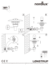 Nordlux Lonstrup 71412031 Mounting Instruction
-
-
Legrand HBP-100 Series High/Low BayPIR Occupancy Sensor (TriLingual) Guide d'installation
-
Malmbergs 99 720 13-15 Malmbergs Breda LED Manuel utilisateur
-
CP Electronics UHS5 Compact Infra Red Commissioning Handset Manuel utilisateur
-
-
Stonco Garage and Canopy DualSelect Install Instructions

