
EN
English - Instruction manual
IT
Italiano - Manuale di istruzioni
FR
Français - Manuel d’instructions
DE
Deutsch - Bedienungsanleitung
RU
Русский - Руководство по эксплуатации
ENGLISH
NXW
Liquid-cooled camera housing


EN
English - Instruction manual
ENGLISH
NXW
Liquid-cooled camera housing

Contents
ENGLISH 1
1 About this manual ....................................................................................................................3
1.1 Typographical conventions ................................................................................................................................................ 3
2 Notes on copyright and information on trademarks ............................................................3
3 Safety rules ...............................................................................................................................3
4 Identification ............................................................................................................................4
4.1 Product description and type designation................................................................................................................... 4
4.2 Product marking label.......................................................................................................................................................... 4
5 Preparing the product for use .................................................................................................4
5.1 Unpacking ................................................................................................................................................................................. 4
5.2 Contents .................................................................................................................................................................................... 4
5.3 Safely disposing of packaging material ......................................................................................................................... 4
6 Installation ................................................................................................................................5
6.1 Preparing the housing .......................................................................................................................................................... 5
6.2 Housing opening ................................................................................................................................................................... 6
6.3 How to install the camera ................................................................................................................................................... 6
6.4 Housing closure ...................................................................................................................................................................... 6
6.5 Installing the housing ........................................................................................................................................................... 6
6.6 Cooling circuit ......................................................................................................................................................................... 7
6.6.1 Examples of system dimensioning ................................................................................................................................................... 7
6.7 Front flange with air barrier ............................................................................................................................................... 8
6.7.1 Suggested air capacity and pressure ............................................................................................................................................... 8
7 Accessories ................................................................................................................................9
7.1 Installation of IR-proof glass kit ......................................................................................................................................... 9
8 Cleaning ....................................................................................................................................9
8.1 Cleaning the window ............................................................................................................................................................ 9
9 Information on disposal and recycling ..................................................................................9
10 Technical data .......................................................................................................................10
10.1 General ...................................................................................................................................................................................10
10.2 Mechanical ........................................................................................................................................................................... 10
10.3 Housing's window ............................................................................................................................................................. 11
10.4 Electrical ................................................................................................................................................................................ 11
10.5 Environment ........................................................................................................................................................................ 11
10.6 Certifications........................................................................................................................................................................ 11
11 Technical drawings ...............................................................................................................12

Instruction manual - English - EN
3MNVCNXW_2222_EN
1 About this manual
Read all the documentation supplied carefully
before installing and using this product. Keep the
manual in a convenient place for future reference.
1.1 Typographical conventions
DANGER!
High level hazard.
Risk of electric shock. Disconnect the
power supply before proceeding with any
operation, unless indicated otherwise.
CAUTION!
Medium level hazard.
This operation is very important for the
system to function properly. Please read
the procedure described very carefully
and carry it out as instructed.
INFO
Description of system specifications.
We recommend reading this part carefully
in order to understand the subsequent
stages.
2 Notes on copyright and
information on trademarks
The mentioned names of products or companies are
trademarks or registered trademarks.
3 Safety rules
CAUTION! Device installation and
maintaining must be performed by
specialist technical staff only.
CAUTION! The electrical system to which
the unit is connected must be equipped
with a 10A max automatic bipolar circuit
breaker. The minimum distance between
the circuit breaker contacts must be
3mm (0.1in). The circuit breaker must be
provided with protection against the fault
current towards the ground (differential)
and the overcurrent (magnetothermal).
• The manufacturer declines all responsibility
for any damage caused by an improper use
of the appliances mentioned in this manual.
Furthermore, the manufacturer reserves the right
to modify its contents without any prior notice.
The documentation contained in this manual has
been collected and verified with great care. The
manufacturer, however, cannot take any liability
for its use. The same thing can be said for any
person or company involved in the creation and
production of this manual.
• Before starting any operation, make sure the
power supply is disconnected.
• Be careful not to use cables that seem worn or old.
• Never, under any circumstances, make any
changes or connections that are not shown in
this handbook. Improper use of the appliance
can cause serious hazards, risking the safety of
personnel and of the installation.
• Use only original spare parts. Non-original spare
parts could cause fire, electrical discharge or other
hazards.
• Before proceeding with installation, check the
supplied material to make sure it corresponds
to the order specification by examining the
identification labels (4.2 Product marking label,
page 4).
• The equipment is intended for installation in a
Restricted Access Area by specialist technical staff.

EN - English - Instruction manual
4 MNVCNXW_2222_EN
4 Identification
4.1 Product description and type
designation
The solid construction of this housing makes it
suitable for heavy-duty applications, such as the
surveillance of ovens, foundries and other high-
temperature environments.
The NXW housing, entirely made of polished
stainless steel, consists of a body with double
chamber for the circulation of coolant or cooling
air, closed by two very thick flanges. The rear
flange enables cable passage using two cable
glands PG13.5. The front flange can be equipped
with tempered glass or quartz glass for high
temperatures.
4.2 Product marking label
See the label attached to the product.
Check the label on the product packaging.
5 Preparing the product for
use
Any change that is not expressly approved
by the manufacturer will invalidate the
guarantee.
5.1 Unpacking
When the product is delivered, make sure that the
package is intact and that there are no signs that it
has been dropped or scratched.
If there are obvious signs of damage, contact the
supplier immediately.
When returning a faulty product we recommend
using the original packaging for shipping.
Keep the packaging in case you need to send the
product for repairs.
5.2 Contents
Check the contents to make sure they correspond
with the list of materials as below:
• Housing
• Housing equipment:
• Allen wrench
• Spacers
• Bolts and screws
• Instruction manual
5.3 Safely disposing of packaging
material
The packaging material can all be recycled. The
installer technician will be responsible for separating
the material for disposal, and in any case for
compliance with the legislation in force where the
device is to be used.

Instruction manual - English - EN
5MNVCNXW_2222_EN
6 Installation
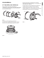
6.1 Preparing the housing
Dismantle the front flange (01) of the housing by
unscrewing the four screws (02) with the hexagonal
wrench (03) provided.
02
01 03
Fig. 1
Position the glass in its seating on the flange, after
correctly inserting the O-rings in the order as shown.
Fig. 2
If there is an IR-proof filter glass, see the specific
assembly instructions (7.1 Installation of IR-proof
glass kit, page 9).
Position the front flange of the housing on the body,
making sure that the sealing rings are correctly
inserted in their seating so as not to damage
them. Tighten the 4 screws using the allen wrench
supplied.
Fig. 3

EN - English - Instruction manual
6 MNVCNXW_2222_EN
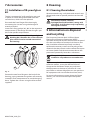
6.2 Housing opening
Unscrew the screws (01) on the rear flange (02) using
the hexagonal wrench (03) provided.
Slide out the rear cover plate of the housing, taking
care to leave the sealing washer in its seating.
By doing so, you can access inside the housing
without dismantling the support bracket.
01
02
03
Fig. 4
6.3 How to install the camera
Open the housing as described in the relative
chapter (6.2 Housing opening, page 6).
Assemble the camera on the slide using the
insulating spacer (01) and the 1/4” screw and the
washer (02) provided. If necessary, use the spacers to
position the camera and lens correctly.
02
01
Fig. 5
Insert the cables through the cable glands and
electrically connect.
Ensure the cable glands are firmly fastened.
6.4 Housing closure
Pay attention to the fixing. Tightening
torque: 4Nm.
After installation and wiring, close the product.
Pay attention not to damage the gasket.
Make sure that the sealing ring is correctly fitted in
its position.
6.5 Installing the housing
Pay attention to the fixing. Tightening
torque: 4Nm.
Fasten the housing to the bracket using the screws
provided.
Fig. 6

Instruction manual - English - EN
7MNVCNXW_2222_EN
6.6 Cooling circuit
The housing is equipped with an input and output
joint on the cooling circuit, both of which are
threaded 1/2” Gas.
Installation and dispersal of heat requirements
mean the position of the input and output joints on
the cooling circuit must be adapted to the specific
situation.
The two joints on the cooling circuit placed near
the front (01) and rear (02) flange can be used
indifferently for cooling liquid input and output.
If necessary, the housing can be rotated on its fixing
base by loosening the two fixing clips (03).
01
02 03
OUT/IN
IN/OUT
Fig. 7
6.6.1 Examples of system dimensioning
The following test data refer to use of water as
a cooling liquid, with an input temperature of
the housing of 20°C and a maximum ambient
temperature of 400°C.
WATER COOLING CIRCUIT WITH INPUT WATER AT A
TEMPERATURE OF 20°C
T environment
(°C)
Water flow rate
(l/min)
T inside housing
(°C)
200 232
300 2.2 41
400 6.5 44
Tab. 1
The following test data refer to cooling with air, at
an input temperature of the housing of 17°C and a
maximum ambient temperature of 80°C.
AIR COOLING CIRCUIT WITH INPUT AIR AT A TEMPERATURE OF
17°C
T envi-
ronment
(°C)
Air pressure
(bar)
Air capacity
(m³/h)
T inside
housing
(°C)
80 110 45
80 215 35
Tab. 2

EN - English - Instruction manual
8 MNVCNXW_2222_EN
6.7 Front flange with air barrier
The flange with air barrier is equipped with a 1/4”Gas
thread joint and a reduction from 1/2”Gas to 1/4”Gas.
This joint must be connected to the circuit with
compressed air supplied by a compressor.
Fig. 8
6.7.1 Suggested air capacity and
pressure
Upstream of the housing , you are advised to install:
• Pressure gauge.
• Adjustment valve.
• Optional filters unit for compressed air cleaning
(NXFIGRU2, filtration 0.1μm).
This allows you to:
• Know and adjust the pressure to supply to the
air barrier.
• Conduct simple maintenance.
Too high pressure values can cause
breakage of the window. Strictly comply
with the maximum values listed below:
Flange with 8 holes with double IR-proof
glass
• System pressure: 4bar max
• Recommended minimum pressure: 2bar
Flange with 32 holes with tempered glass
• System pressure: 6bar max
• Recommended minimum pressure: 2bar
For example purposes, the system pressure-output
pressure and system pressure-air capacity graphics
are outlined which are useful for compressor
dimensioning. All the values must be considered as
purely approximate.
01 2 3 4 5 6
0.4
0.2
0.6
0.8
1
1.2
1.4
Flange with
8 holes
Flange with
32 holes
System pressure (bar)
Output pressure (bar)
Fig. 9
01 2 3 4 5 6
40
20
60
80
100
Flange with
8 holes
Flange with
32 holes
System pressure (bar)
Air capacity (m³/h)
Fig. 10

Instruction manual - English - EN
9MNVCNXW_2222_EN
7 Accessories
7.1 Installation of IR-proof glass
kit
The kit is composed of an IR-proof glass pair and
a special air barrier flange that differs from the
standard one, which must be replaced.
Dismantle the front flange of the housing by
unscrewing the 4 screws using the hexagonal
wrench provided.
Insert the O-Ring gaskets (01), (02) in the respective
compartments in the flange. Position the glass pair
(03) in the specific compartment.
Correct orientation of the IR-proof glass.
Marking (04) identifies the surface of each
glass which must be turned outwards of
the housing.
02
01
04
03
Fig. 11
Position the new front flange on the body of the
housing, paying attention the gaskets are correctly
inserted in their compartments to avoid damaging
them. Tighten the 4 screws using the allen wrench
supplied.
8 Cleaning
8.1 Cleaning the window
We recommend using a soft cloth with neutral soap
diluted with water or specific products to clean the
lenses.
Avoid ethyl alcohol, solvents,
hydrogenated hydrocarbide, strong acid
and alkali. Such products may irreparably
damage the surface.
9 Information on disposal
and recycling
The European Directive 2012/19/EU on Waste
Electrical and Electronic Equipment (WEEE)
mandates that these devices should not be disposed
of in the normal flow of municipal solid waste, but
they should be collected separately in order to
optimize the recovery stream and recycling of the
materials that they contain and to reduce the impact
on human health and the environment due to the
presence of potentially hazardous substances.
The symbol of the crossed out bin is
marked on all products to remember this.
The waste may be delivered to appropriate
collection centers, or may be delivered free of
charge to the distributor where you purchased
the equipment at the time of purchase of a new
equivalent or without obligation to a new purchase
for equipment with size smaller than 25cm (9.8in).
For more information on proper disposal of these
devices, you can contact the responsible public
service.

EN - English - Instruction manual
10 MNVCNXW_2222_EN
10 Technical data
10.1 General
Housing manufactured in polished stainless steel
(austenitic stainless alloy steel resistant to corrosion
and heat):
• AISI 316L
• UNI 6900-71: X 2 Cr Ni Mo 17 12 2
• DIN 17006: X 2 Cr Ni Mo 17 13 2
• N° werkstoff: 1.4404
• AFNOR: Z2 CND 17-12
• BSI: 316S11
The screws utilised are in austenitic alloy stainless
steel, corrosion and heat resistant according to the
following standards:
• ISO: 7380
• AISI: 316
• ISO quality: A4
• Resistance class ISO: from 50 to 70
10.2 Mechanical
External body polishing
Dimensions (ØxL): 154x375mm (6x14.8in)
Internal usable dimensions (WxH): 78x78mm (3.1x
3.1in)
Internal usable length: 345mm (13.6in)
Internal usable length (with power supply): 223mm
(8.8in)
2x1/2”GAS connectors for liquid input / output
The flange with air barrier is equipped with a 1/4”Gas
thread joint and a reduction from 1/2”Gas to 1/4”Gas.
Gaskets: O-ring
Flange thickness (back) : 9mm (0.35in)
Cable glands: 2xPG13.5 (nickel-plated brass)
Cooling liquid (application example with incoming
water at 20°C (68°F) temperature):
• ambient temperature 200°C (392°F), water
capacity 2l/min, temperature inside housing 32°C
(89.6°F)
• ambient temperature 300°C (572°F), water
capacity 2.2l/min, temperature inside housing
41°C (105.8°F)
• ambient temperature 400°C (752°F), water
capacity 6.5l/min, temperature inside housing
44°C (111.2°F)
Cooling Air (Application example with incoming air
at 17°C(62°F) and an environmental temperature at
80°C(176°F)):
• with pressure 1bar, air capacity 10m³/h,
temperature inside housing 45°C (113°F)
• with pressure 2bar, air capacity 15m³/h,
temperature inside housing 35°C (95°F)
Air barrier (Flange with 8 holes)
• Male input 1/2” GAS
• System pressure: 4bar max
• Recommended minimum pressure: 2bar
Air barrier (Flange with 32 holes)
• Male input 1/2” GAS
• System pressure: 6bar max
• Recommended minimum pressure: 2bar
Unit weight: 10.2kg (22lb)

Instruction manual - English - EN
11MNVCNXW_2222_EN
10.3 Housing's window
Usable diameter: 95mm (3.7in)
Tempered extra clear glass
• Thick: 6mm (0.24in)
• Operating temperature: 260°C (500°F) max,
thermal gradient 108°C (226.4°F) max
Quartz glass
• Thick: 6mm (0.24in)
• Operating temperature: 400°C (752°F) max,
thermal gradient 220°C (428°F) max
IR-proof glass
• Thick: 6.6mm (0.3in)
• Operating temperature: 260°C (500°F) max,
thermal gradient 108°C (226.4°F) max
10.4 Electrical
Camera power supply
IN from 100Vac up to 240Vac, 50/60Hz - OUT 12Vdc,
1.25A
IN 230Vac, 50/60Hz - OUT 24Vac, 400mA
10.5 Environment
For indoors and outdoors installation
Maximum working temperature (with water cooling):
• with tempered glass 260°C (500°F) max
• with quartz glass 400°C (752°F) max
• with IR-proof glass 260°C (500°F) max
Relative humidity: from 5% up to 95%
10.6 Certifications
Electrical safety (CE): EN60065, EN62368-1
Electromagnetic compatibility (CE): EN50130-4,
EN61000-6-3
IP protection degree: EN60529, IP66/IP67
EAC certification

MNVCNXW_2222_EN
11 Technical drawings
The indicated measurements are expressed in millimetres.
78
130
Ø 101.5
M5
115
78
164
60
94
A
A
87
B - B
Ø 95
21 345
223
9
Ø 154
20
A - A
1/2" GAS
1/4" GAS
28
28
1/2" GAS
1/2" GAS
375
116.5
B
B
USABLE AREA
(WITH POWER SUPPLY)
USABLE
AREA
FIXING BASE
Fig. 12 NXW.
Headquarters Italy VIDEOTEC s.r.l.
Via Friuli, 6 - I-36015 Schio (VI) - Italy
Tel. +39 0445 697411 - Fax +39 0445 697414
Email: [email protected]
www.videotec.com

IT
Italiano - Manuale di istruzioni
ITALIANO
NXW
Custodia per telecamera raffreddata a liquido

Sommario
ITALIANO 1
1 Informazioni sul presente manuale........................................................................................3
1.1 Convenzioni tipografiche .................................................................................................................................................... 3
2 Note sul copyright e informazioni sui marchi commerciali .................................................3
3 Norme di sicurezza ...................................................................................................................3
4 Identificazione ..........................................................................................................................4
4.1 Descrizione e designazione del prodotto ..................................................................................................................... 4
4.2 Etichetta di marcatura del prodotto ............................................................................................................................... 4
5 Preparazione del prodotto per l'utilizzo................................................................................4
5.1 Disimballaggio ........................................................................................................................................................................ 4
5.2 Contenuto ................................................................................................................................................................................. 4
5.3 Smaltimento in sicurezza dei materiali di imballaggio ............................................................................................ 4
6 Installazione .............................................................................................................................5
6.1 Preparazione della custodia ............................................................................................................................................... 5
6.2 Apertura della custodia ....................................................................................................................................................... 6
6.3 Installazione della telecamera .......................................................................................................................................... 6
6.4 Chiusura della custodia ........................................................................................................................................................ 6
6.5 Installazione della custodia ................................................................................................................................................ 6
6.6 Circuito di raffreddamento ................................................................................................................................................. 7
6.6.1 Esempi di dimensionamento dell'impianto .................................................................................................................................. 7
6.7 Flangia anteriore con barriera d'aria ............................................................................................................................... 8
6.7.1 Portate e pressioni d'aria suggerite .................................................................................................................................................. 8
7 Accessori ...................................................................................................................................9
7.1 Installazione del kit vetro anti IR ....................................................................................................................................... 9
8 Pulizia ........................................................................................................................................ 9
8.1 Pulizia della finestra ............................................................................................................................................................... 9
9 Informazioni sullo smaltimento e il riciclo ............................................................................ 9
10 Dati tecnici ............................................................................................................................10
10.1 Generale ................................................................................................................................................................................10
10.2 Meccanica .............................................................................................................................................................................10
10.3 Finestre per custodia ........................................................................................................................................................ 11
10.4 Elettrico.................................................................................................................................................................................. 11
10.5 Ambiente .............................................................................................................................................................................. 11
10.6 Certificazioni ........................................................................................................................................................................ 11
11 Disegni tecnici ...................................................................................................................... 12

Manuale di istruzioni - Italiano - IT
3MNVCNXW_2222_IT
1 Informazioni sul presente
manuale
Prima di installare e utilizzare questo prodotto
leggere attentamente tutta la documentazione
fornita. Tenere il manuale a portata di mano per
consultazioni successive.
1.1 Convenzioni tipografiche
PERICOLO!
Pericolosità elevata.
Rischio di scosse elettriche. Prima di
eseguire qualsiasi operazione assicurarsi
di togliere tensione al prodotto, salvo
diversa indicazione.
ATTENZIONE!
Pericolosità media.
L'operazione è molto importante per
il corretto funzionamento del sistema.
Si prega di leggere attentamente la
procedura indicata e di eseguirla secondo
le modalità previste.
INFO
Descrizione delle caratteristiche del
sistema.
Si consiglia di leggere attentamente per
comprendere le fasi successive.
2 Note sul copyright e
informazioni sui marchi
commerciali
I nomi di prodotto o di aziende citati sono marchi
commerciali o marchi commerciali registrati
appartenenti alle rispettive società.
3 Norme di sicurezza
ATTENZIONE! L'installazione e la
manutenzione del dispositivo devono
essere eseguite solo da personale tecnico
specializzato.
ATTENZIONE! L’impianto elettrico al quale
è collegata l’unità deve essere dotato di
un interruttore di protezione bipolare
automatico da 10A max. La distanza
minima tra i contatti dell'interruttore
di protezione deve essere di 3mm.
L’interruttore deve essere provvisto
di protezione contro la corrente di
guasto verso terra (differenziale) e la
sovracorrente (magnetotermico).
• Il produttore declina ogni responsabilità per
eventuali danni derivanti da un uso improprio
delle apparecchiature menzionate in questo
manuale. Si riserva inoltre il diritto di modificarne
il contenuto senza preavviso. Ogni cura è
stata posta nella raccolta e nella verifica della
documentazione contenuta in questo manuale.
Il produttore, tuttavia, non può assumersi alcuna
responsabilità derivante dall'utilizzo della stessa.
Lo stesso dicasi per ogni persona o società
coinvolta nella creazione e nella produzione di
questo manuale.
• Prima di eseguire qualsiasi operazione assicurarsi
di togliere tensione al prodotto.
• Non utilizzare cavi con segni di usura o
invecchiamento.
• Non effettuare per nessun motivo alterazioni o
collegamenti non previsti in questo manuale.
L'uso di apparecchi non idonei può portare a
gravi pericoli per la sicurezza del personale e
dell'impianto.
• Utilizzare solo parti di ricambio originali. Pezzi
di ricambio non originali potrebbero causare
incendi, scariche elettriche o altri pericoli.
• Prima di procedere con l'installazione, controllare
che il materiale fornito corrisponda alle specifiche
richieste esaminando le etichette di marcatura (
4.2 Etichetta di marcatura del prodotto, pagina 4).
• L'apparecchio è destinato all'installazione
in un'Area ad Accesso Limitato effettuata da
personale tecnico specializzato.

IT - Italiano - Manuale di istruzioni
4 MNVCNXW_2222_IT
4 Identificazione
4.1 Descrizione e designazione
del prodotto
La costruzione eccezionalmente robusta di questa
custodia la rende adatta alle applicazioni più pesanti,
per la sorveglianza di forni, fonderie e ambienti in
cui si sviluppino alte temperature.
La custodia NXW, interamente costruita in acciaio
Inox brillantato, è costituita da un corpo con doppia
camera per la circolazione del liquido o dell’aria di
raffreddamento, chiuso da due flange di elevato
spessore. La flangia posteriore permette il passaggio
dei cavi mediante due pressacavi PG13.5. La flangia
anteriore può essere dotata di vetro temprato
oppure di vetro al quarzo per temperature superiori.
4.2 Etichetta di marcatura del
prodotto
Vedere l’etichetta posta sul prodotto.
Controllare l’etichetta posta sull'imballo del
prodotto.
5 Preparazione del prodotto
per l'utilizzo
Qualsiasi intervento non espressamente
approvato dal costruttore fa decadere la
garanzia.
5.1 Disimballaggio
Alla consegna del prodotto verificare che l'imballo
sia integro e non presenti segni evidenti di cadute o
abrasioni.
In caso di danni evidenti all'imballo contattare
immediatamente il fornitore.
In caso di restituzione del prodotto malfunzionante
è consigliato l'utilizzo dell'imballo originale per il
trasporto.
Conservare l'imballo qualora fosse necessario inviare
il prodotto in riparazione.
5.2 Contenuto
Controllare che il contenuto sia corrispondente alla
lista del materiale sotto elencato:
• Custodia
• Dotazione per custodia:
• Chiave esagonale
• Distanziali
• Viteria
• Manuale di istruzioni
5.3 Smaltimento in sicurezza dei
materiali di imballaggio
I materiali d'imballo sono costituiti interamente da
materiale riciclabile. Sarà cura del tecnico installatore
smaltirli secondo le modalità di raccolta differenziata
o comunque secondo le norme vigenti nel Paese di
utilizzo.

Manuale di istruzioni - Italiano - IT
5MNVCNXW_2222_IT
6 Installazione
6.1 Preparazione della custodia
Smontare la flangia anteriore (01) della custodia
svitando le quattro viti (02) con la chiave esagonale
(03) in dotazione.
02
01 03
Fig. 1
Posizionare il vetro nella propria sede sulla flangia
dopo aver inserito correttamente le guarnizioni
O-Ring con la sequenza indicata.
Fig. 2
Nel caso di vetro filtro anti IR vedere le successive
istruzioni specifiche di montaggio (7.1 Installazione
del kit vetro anti IR, pagina 9).
Posizionare la flangia frontale della custodia sul
corpo prestando attenzione che le guarnizioni di
tenuta siano correttamente inserite nelle proprie
sedi in modo da non danneggiarle. Serrare le 4 viti
utilizzando la chiave esagonale in dotazione.
Fig. 3

IT - Italiano - Manuale di istruzioni
6 MNVCNXW_2222_IT
6.2 Apertura della custodia
Svitare le viti (01) poste sulla flangia posteriore (02)
utilizzando la chiave esagonale (03) in dotazione.
Sfilare il fondo della custodia prestando attenzione
che la guarnizione rimanga in sede.
Così facendo sarà possibile accedere all'interno della
custodia senza smontarla dalla staffa di sostegno.
01
02
03
Fig. 4
6.3 Installazione della telecamera
Aprire la custodia come descritto nel relativo
capitolo (6.2 Apertura della custodia, pagina 6).
Montare la telecamera sulla slitta utilizzando il
distanziale isolante (01), la vite da 1/4” e la rondella
(02) in dotazione. Se necessario utilizzare i distanziali
per posizionare nel modo corretto telecamera ed
ottica.
02
01
Fig. 5
Inserire i cavi attraverso i pressacavi ed eseguire le
connessioni elettriche necessarie. Assicurarsi che i
pressacavi siano fissati saldamente.
6.4 Chiusura della custodia
Prestare attenzione durante il fissaggio.
Coppia di serraggio: 4Nm.
Al termine delle operazioni di installazione e
cablaggio richiudere il prodotto.
Prestare attenzione a non danneggiare la
guarnizione di tenuta.
Assicurarsi che la guarnizione sia correttamente
inserita nella propria sede.
6.5 Installazione della custodia
Prestare attenzione durante il fissaggio.
Coppia di serraggio: 4Nm.
Fissare la custodia sulla staffa utilizzando le viti
fornite in dotazione.
Fig. 6
La page est en cours de chargement...
La page est en cours de chargement...
La page est en cours de chargement...
La page est en cours de chargement...
La page est en cours de chargement...
La page est en cours de chargement...
La page est en cours de chargement...
La page est en cours de chargement...
La page est en cours de chargement...
La page est en cours de chargement...
La page est en cours de chargement...
La page est en cours de chargement...
La page est en cours de chargement...
La page est en cours de chargement...
La page est en cours de chargement...
La page est en cours de chargement...
La page est en cours de chargement...
La page est en cours de chargement...
La page est en cours de chargement...
La page est en cours de chargement...
La page est en cours de chargement...
La page est en cours de chargement...
La page est en cours de chargement...
La page est en cours de chargement...
La page est en cours de chargement...
La page est en cours de chargement...
La page est en cours de chargement...
La page est en cours de chargement...
La page est en cours de chargement...
La page est en cours de chargement...
La page est en cours de chargement...
La page est en cours de chargement...
La page est en cours de chargement...
La page est en cours de chargement...
La page est en cours de chargement...
La page est en cours de chargement...
La page est en cours de chargement...
La page est en cours de chargement...
La page est en cours de chargement...
La page est en cours de chargement...
La page est en cours de chargement...
La page est en cours de chargement...
La page est en cours de chargement...
La page est en cours de chargement...
-
 1
1
-
 2
2
-
 3
3
-
 4
4
-
 5
5
-
 6
6
-
 7
7
-
 8
8
-
 9
9
-
 10
10
-
 11
11
-
 12
12
-
 13
13
-
 14
14
-
 15
15
-
 16
16
-
 17
17
-
 18
18
-
 19
19
-
 20
20
-
 21
21
-
 22
22
-
 23
23
-
 24
24
-
 25
25
-
 26
26
-
 27
27
-
 28
28
-
 29
29
-
 30
30
-
 31
31
-
 32
32
-
 33
33
-
 34
34
-
 35
35
-
 36
36
-
 37
37
-
 38
38
-
 39
39
-
 40
40
-
 41
41
-
 42
42
-
 43
43
-
 44
44
-
 45
45
-
 46
46
-
 47
47
-
 48
48
-
 49
49
-
 50
50
-
 51
51
-
 52
52
-
 53
53
-
 54
54
-
 55
55
-
 56
56
-
 57
57
-
 58
58
-
 59
59
-
 60
60
-
 61
61
-
 62
62
-
 63
63
-
 64
64


dans d''autres langues
- italiano: Videotec NXW Series Manuale utente
- Deutsch: Videotec NXW Series Benutzerhandbuch
Documents connexes
-
Videotec NXW Manuel utilisateur
-
Videotec NTW Manuel utilisateur
-
-
-
-
Videotec EXH Manuel utilisateur
-
-
-
-