
T200 SERIES THERMAL TRANSFER PRINTER
SYSTEM USER’S GUIDE
(T208M-PRINTER, T208M-C-PRINTER, T212M-PRINTER & T212M-C-PRINTER)

T200 SERIES THERMAL TRANSFER PRINTER
SYSTEM USER’S GUIDE
(T208M-PRINTER, T208M-C-PRINTER, T212M-PRINTER & T212M-C-PRINTER)
APPROVALS NAME SIGNED DATE
TECHNICAL J. SWIFT
30/07/07
TECHNICAL SUPPORT J. SMITH
30/07/07
PRODUCT MANAGEMENT R. SWIFT
30/07/07
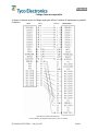
Revision History
Rev No CR No Date Incorporated By
1 Original Issue July 2002 Graham Leat & Mario Appello
2 Merged 4 languages November 2002 Jim Smith
3 Complete update March 2003 Graham Leat
4 Updated for New Model September 2004 Jim Smith
5 Made model have -Printer October 2004 Jim Smith
6 New logo & contents added July 2007 Jim Smith
7
8
9

Contents
English .....................................................................................................................1
Forward ......................................................................................................................................2
Important Information!...............................................................................................................3
1.0 Printer Set-up..................................................................................................................4
1.1 Unpacking the Printer.................................................................................................4
1.2 Printer Overview ........................................................................................................5
1.3 Attaching the Power Supply To The Printer..............................................................6
1.4 Connecting the Interface Cable..................................................................................7
2.0 Ribbon Selection ............................................................................................................8
3.0 Loading Ribbon..............................................................................................................8
3.1 Adding a New Ribbon................................................................................................9
3.2 Removing a partially used Ribbon.............................................................................9
4.0 Loading Product...........................................................................................................10
4.1 Loading TMS Marker Sleeves .................................................................................11
4.2 Loading Labels.........................................................................................................12
4.3 Loading Product Cont… ..........................................................................................13
5.0 Calibration....................................................................................................................14
5.1 Alignment For Calibration .......................................................................................15
6.0 Changing Sensor Type .................................................................................................16
6.1 Reflective (Black Mark) Sensor...............................................................................16
6.2 Continuous Sensing Mode........................................................................................16
6.3 Transmissive Sensor.................................................................................................16
7.0 Printer Firmware Versions ...........................................................................................16
8.0 Software........................................................................................................................17
9.0 Print Quality.................................................................................................................17
10.0 Maintenance .................................................................................................................18
10.1 Cleaning the Print Head ...........................................................................................18
10.2 Cleaning the Platen Roller........................................................................................19
11.0 Troubleshooting............................................................................................................20
Appendix A ..............................................................................................................................21
T200 Series with Cutter........................................................................................................21
Clearing the Media Cutter....................................................................................................22
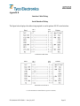
Appendix B...............................................................................................................................23
Interface Cable Wiring.........................................................................................................23
Francàis .................................................................................................................26
Avant-propos............................................................................................................................27
Information importante !..........................................................................................................28
1.0 Installation de l’imprimante .........................................................................................29
1.1 Déballage de l’imprimante.......................................................................................29
1.2 Vue d’ensemble de l’imprimante .............................................................................30
1.3 Branchement de l’adaptateur d’alimentation électrique de l’imprimante................31
1.4 Connexion du câble d’interface................................................................................32
2.0 Choix du ruban.............................................................................................................33
3.0 Chargement du ruban ...................................................................................................33

3.1 Insertion d’un ruban neuf.........................................................................................34
3.2 Retrait d’un ruban partiellement usagé ....................................................................34
4.0 Chargement du produit.................................................................................................35
4.1 Chargement des manchons de marquage TMS........................................................36
4.2 Chargement d’étiquettes...........................................................................................37
4.3 Chargement du produit (suite)..................................................................................38
5.0 Calibrage ......................................................................................................................39
5.1 Alignement de calibrage...........................................................................................40
6.0 Changement du type de capteur ...................................................................................41
6.1 Capteur réflectif (marque noire)...............................................................................41
6.2 Mode de détection continue .....................................................................................41
6.3 Capteur transmissif...................................................................................................41
7.0 Versions du micrologiciel de l’imprimante..................................................................41
8.0 Logiciel.........................................................................................................................42
9.0 Qualité d’impression ....................................................................................................42
10.0 Entretien .......................................................................................................................43
10.1 Nettoyage de la tête d’impression............................................................................43
10.2 Nettoyage du rouleau de la platine...........................................................................44
11.0 Dépannage....................................................................................................................45
Annexe A..................................................................................................................................46
Série T200 avec massicot.....................................................................................................46
Déblocage du massicot de support.......................................................................................47
Annexe B..................................................................................................................................48
Câblage du câble d’interface................................................................................................48
Deutsch...................................................................................................................51
Vorwort ....................................................................................................................................52
Wichtige Information!..............................................................................................................53
1.0 Aufbau des Druckers....................................................................................................54
1.1 Den Drucker auspacken............................................................................................54
1.2 Überblick über den Drucker.....................................................................................55
1.3 Anschluss des Druckers an die Stromversorgung....................................................56
1.4 Anschluss des Interface-Kabels................................................................................57
2.0 Auswahl des Farbbands................................................................................................58
3.0 Einlegen des Farbbands................................................................................................58
3.1 Ein neues Farbband einlegen....................................................................................59
3.2 Entfernen eines teilweise gebrauchten Farbbands ...................................................59
4.0 Einlegen von Druckmedien..........................................................................................60
4.1 Einlegen der TMS Markierungsbanderolen.............................................................61
4.2 Einlegen von Etiketten .............................................................................................62
4.3 Einlegen von Druckmedien Fortsetzung..................................................................63
5.0 Kalibrierung..................................................................................................................64
5.1 Ausrichtung zur Kalibrierung...................................................................................65
6.0 Wechsel des Sensortyps ...............................................................................................66
6.1 Reflektionssensor (schwarze Markierung)...............................................................66
6.2 Endlosdruck-Sensor..................................................................................................66
6.3 Sensor für lichtdurchlässige Druckmedien...............................................................66

7.0 Drucker-Firmware-Versionen......................................................................................67
8.0 Software........................................................................................................................67
9.0 Druckqualität................................................................................................................67
10.0 Wartung........................................................................................................................68
10.1 Reinigung des Druckkopfes .....................................................................................68
10.2 Reinigung der Walzenrolle.......................................................................................69
11.0 Fehlerbehebung............................................................................................................70
Anhang A .................................................................................................................................71
T200 Serie mit Schneideinrichtung......................................................................................71
Reinigen der Schneideinrichtung .........................................................................................72
Anhang B..................................................................................................................................73
Interfacekabel-Verdrahtung..................................................................................................73
Español...................................................................................................................76
Objeto.......................................................................................................................................77
Información importante............................................................................................................78
1.0 Configuración de la impresora.....................................................................................79
1.1 Desembalaje de la impresora....................................................................................79
1.2 Visión de conjunto de la impresora..........................................................................80
1.3 Conexión de la impresora a la red eléctrica .............................................................81
1.4 Conexión del cable de interfaz.................................................................................82
2.0 Selección de cinta.........................................................................................................83
3.0 Carga de la cinta...........................................................................................................83
3.1 Adición de una nueva cinta......................................................................................84
3.2 Retirada de una cinta parcialmente usada ................................................................84
4.0 Carga del producto .......................................................................................................85
4.1 Carga de las fundas para marcar TMS .....................................................................86
4.2 Carga de las etiquetas...............................................................................................87
4.3 Carga del producto cont. ..........................................................................................88
5.0 Calibrado......................................................................................................................89
5.1 Alineación para el calibrado.....................................................................................90
6.0 Cambio del tipo de sensor............................................................................................91
6.1 Sensor reflectante (marca negra)..............................................................................91
6.2 Modo de detección continua.....................................................................................91
6.3 Sensor transmisor.....................................................................................................91
7.0 Versiones de microprogramación de la impresora.......................................................91
8.0 Software........................................................................................................................92
9.0 Calidad de impresión....................................................................................................92
10.0 Mantenimiento..............................................................................................................93
10.1 Limpieza del cabezal de impresión..........................................................................93
10.2 Limpieza del rodillo de platina.................................................................................94
11.0 Resolución de problemas..............................................................................................95
Apéndice A...............................................................................................................................96
Serie T200 con guillotina.....................................................................................................96
Retirada de residuos de la guillotina ....................................................................................97
Apéndice B...............................................................................................................................98
Instalación del cable de interfaz...........................................................................................98

English
EIL/MAN/002: REVISION 6 Date: July 2007 Page 1
English
T200 SERIES THERMAL TRANSFER PRINTER
SYSTEM USER’S GUIDE
(T208M-PRINTER, T208M-C-PRINTER,T212M-PRINTER & T212M-C-PRINTER)

English
EIL/MAN/002: REVISION 6 Date: July 2007 Page 2
Forward
This manual provides installation and operation information for the T208M-PRINTER (E63660-
000), T208M-C-PRINTER (D82271-000), T212M-PRINTER (E23401-000) and T212M-C-
PRINTER (A53989-000), manufactured for Tyco Electronics.
Copyright Notice
This document contains information proprietary to Tyco Electronics. This document and
information contained within is copyrighted by Tyco Electronics and may not be duplicated in
full or in part by any person without written approval from Tyco Electronics. While every effort
has been made to keep the information contained within current and accurate as of the date of
publication, no guarantee is given or implied that the document is error-free or that it is accurate
with regard to any specification. Tyco Electronics reserve the right to make changes, for the
purpose of product improvement, at any time.
Trademarks
T208M and T212M are service trademarks of Tyco Electronics. Windows and MS-DOS are
registered trademarks of Microsoft Corp. All other marks are trademarks or registered
trademarks of their respective holders.
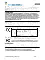
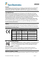
T208M-PRINTER, T208M-C-PRINTER, T212M-PRINTER and T212M-C-PRINTER Thermal Printers
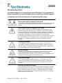
European Council Directive Compliance to Standards
89/336/EEC EMC Directive
EN 55022-B
1988
RF Emissions control
EMC Directive EN 55024 1988
Immunity to Electro-magnetic
Disturbances
92/31/EE EMC Directive EN 61000-3-2 Harmonic Emissions
92/31/EE EMC Directive EN 61000-3-3 Voltage Variation
CB Scheme
EN 60950 1991
A1, A2, A3, A4
Safety
FCC – Declaration of Conformity
Models: T208M-PRINTER, T208M-C-PRINTER, T212M-PRINTER and
T212M-C-PRINTER conform to the following specifications: FCC Part 15,
Subpart B, Section 15.107(a) and Section 15.109(a) Class B digital device.
Supplimental Information:
This device complies with part 15 of the FCC Rules. Operation is subject to the following Two Conditions: (1)
This device may not cause harmfull interference, and (2) this device must accept any interference received,
including interference that may cause undesired operation.
Industry Canada Notice:
This device complies with Industry Canada ICS-003 class B requirements.
Cet equipment est conforme a l’ICS-003 classse B de la norm Industrielle Canadian.

English
EIL/MAN/002: REVISION 6 Date: July 2007 Page 3
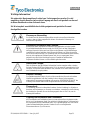
Important Information!
Incorrect use of this equipment can cause injury. It is advised that operators be trained in
the correct use of the equipment and that they read this manual before use.
Maintenance must only be carried out by suitably qualified and trained personnel.
Shock Hazard Warning:
The printer and power supply should never be operated in a location where either one
can get wet. Personal injury could result.
Media and Ribbon Warning:
Always use high quality, approved product and ribbons. If adhesive backed labels are
used the DO NOT lay flat on the backing liner, the exposed edges may stick to the label
guides and rollers inside the printer, causing the label to peel off from the liner and jam
the printer. Permanent damage to the print head may result if a non-approved ribbon is
used as it may be wound incorrectly for the printer or contain chemicals corrosive to the
print head. Approved supplies can be ordered from your dealer.
Reloading Hint:
If labels or ribbon run out while printing, DO NOT turn the power switch OFF (0) while
reloading or data loss may result. The printer automatically restarts after you load a new
label or ribbon roll
Static Discharge:
The discharge of electrostatic energy that accumulates on the surface of the human body
or other surfaces can damage or destroy the print head or electronic components used in
this device. DO NOT TOUGH the print head or the electronic components under the top
cover.
Thermal Printing:
The print head becomes hot while printing. To protect from damage the print head and
risk of personal injury, avoid touching the print head. Use only the cleaning pen or IPA
wipes to perform maintenance.
Product and Ribbon Storage:
All products and ribbons must be kept in a clean area, free from contamination, dust,
grease and condensation. Image quality and durability may be affected if this is not the
case. Storage conditions and shelf-life are marked on each product container. For
further information please contact Tyco Electronics.

English
EIL/MAN/002: REVISION 6 Date: July 2007 Page 4
1.0 Printer Set-up
1.1 Unpacking the Printer
Unpack the printer ensuring that all packaging is retained for future transit. In the unlikely
event of the printer arriving in a less than perfect state, please contact your Tyco Electronics
representative or the shipping agent.
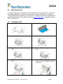
The following should be included with the printer:
• Three power leads: UK, European, US.
• Parallel communications cable.
• Power supply.
• Spare cardboard core (for ribbon take-up).
• Print head cleaning pen.
• Tyco Electronics CD ROM containing…
o Electronic Copy of this User Guide.
o Printer Drivers for Windows 95, 98, Me, NT4, 2K and XP.
o Font Downloader .
o Firmware Downloader – Only to be used when advised by Tyco Electronics.
o Wintotal Demo Software.
o PrintEasy Demo Software.
• Tyco Electronics print contrast scale.

English
EIL/MAN/002: REVISION 6 Date: July 2007 Page 5
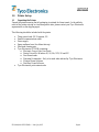
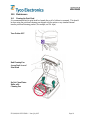
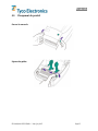
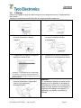
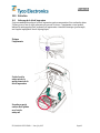
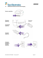
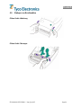
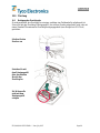
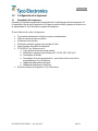
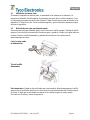
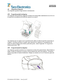
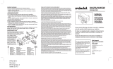
1.2 Printer Overview
Ribbon Sensor
Tear Bar
Top Cover Lock
Supply Ribbon Hub
Take-Up Ribbon Hub
Ribbon Take-Up Gear
Print Head
Media Roll Holders
Media Sensor
Media Guides
Guides Adjustment

English
EIL/MAN/002: REVISION 6 Date: July 2007 Page 6
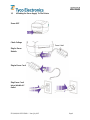
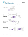
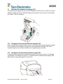
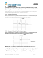
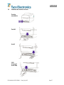
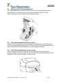
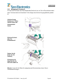
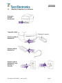
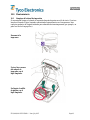
1.3 Attaching the Power Supply To The Printer
Power OFF
Check Voltage
Plug In Power
Module
Plug in Power Cord
Plug Power Cord
into a Suitable AC
Outlet
Power Label

English
EIL/MAN/002: REVISION 6 Date: July 2007 Page 7
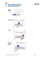
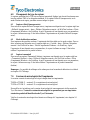
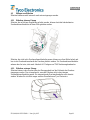
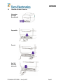
1.4 Connecting the Interface Cable
Power OFF
Parallel
Serial
USB
(Universal
Serial Bus)

English
EIL/MAN/002: REVISION 6 Date: July 2007 Page 8
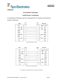
2.0 Ribbon Selection
Print quality and permanency on Tyco Electronics Identification products is only guaranteed if
the correct thermal transfer ribbon is used for each product. Please refer to the
“Printer/material/ribbon compatibility cross reference” found at
www.tycoident.com or contact
Tyco Electronics.
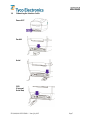
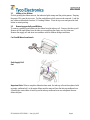
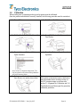
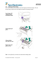
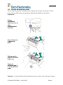
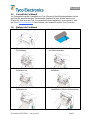
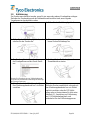
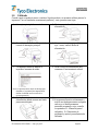
3.0 Loading Ribbon
1. Open Cover.
2. Pull Adhesive Strip Free on ribbon.
3. Thread the ribbon through carriage.
4. Press core onto Hub.
5. Align Notches onto Hub Spokes.
6. Press the take-up core on to the Hub.
7. Align Notches onto Hub Spokes.
8. Attache ribbon to take-up core using
adhesive strip on new ribbons or tape.

English
EIL/MAN/002: REVISION 6 Date: July 2007 Page 9
3.1 Adding a New Ribbon
If while printing the ribbon runs out, the indicator lights orange and the printer pauses. Keeping
the power ON, open the top cover. Cut the used ribbon so both cores can be removed. Load the
new ribbon as described in section 3.0 Loading Ribbon. Close the top cover and press the feed
button to restart printing.
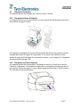
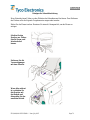
3.2 Removing a partially used Ribbon
To remove a partially used ribbon cut the ribbon from the take-up roll. Remove the take-up roll.
Remove all the used ribbon from the take-up core and keep the empty core for future use.
Remove the supply roll and store in accordance with the ribbons storage conditions.
Cut Used Ribbon from Supply
Push Supply Roll
Out
Important Note: When a complete ribbon has been used, the take-up roll must be replaced with
an empty cardboard roll, or the waste ribbon must be removed from the take-up cardboard core.
Allowing the waste ribbon to build up on the take-up cardboard core can rub against the new
ribbon and jam.

English
EIL/MAN/002: REVISION 6 Date: July 2007 Page 10
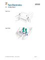
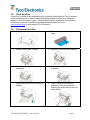
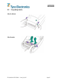
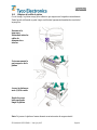
4.0 Loading Product
Open Cover
Open Guides

English
EIL/MAN/002: REVISION 6 Date: July 2007 Page 11
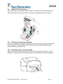
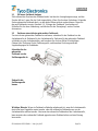
4.1 Loading TMS Marker Sleeves
TMS marker sleeves can be loaded either internally or externally. Both methods require the
Media Roll Holders to be held open and the locking screw tightened using a screwdriver.
4.1.1 TMS Marker Sleeves Internal Loading
Remove all packaging and the large cardboard core and place the product loose into the media
bay of the printer. This is suitable for TMS marker sleeves and some self-adhesive label
products with large cardboard cores.
4.1.2 TMS Marker Sleeves External Loading
Product can be fed into the printer via the rear access slot at the back of the printer. This is
suitable if it is desired to leave TMS marker sleeves in the cardboard box they are shipped in.

English
EIL/MAN/002: REVISION 6 Date: July 2007 Page 12
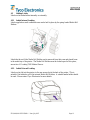
4.2 Loading Labels
Labels can be loaded either internally or externally.
4.2.1 Labels Internal Loading
Labels supplied on small cardboard cores can be held in place by the spring loaded Media Roll
Holders.
Labels that do not fit the Media Roll Holders can be removed from their core and placed loose
in the media bay of the printer. The Media Roll Holders must be locked open for this option,
see section 4.1 Loading TMS Marker Sleeves.
4.2.2 Labels External Loading
Labels can be fed into the printer via the rear access slot at the back of the printer. This is
suitable if the labels do not fit the internal Media Roll Holders. A suitable media holder should
be used. Please contact Tyco Electronics for more details.

English
EIL/MAN/002: REVISION 6 Date: July 2007 Page 13
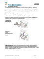
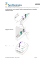
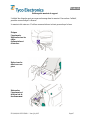
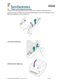
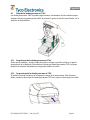
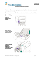
4.3 Loading Product Cont…
The first marker sleeve/label must be positioned on the black rubber pinch roller. Once loaded
close the media guides to lightly grip the product.
Release Cover
Close Cover

English
EIL/MAN/002: REVISION 6 Date: July 2007 Page 14
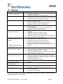
5.0 Calibration
When loading new or changing product types the printer must be calibrated.
Once the product and ribbon are correctly installed, the following procedure must be carried out
1. Power Off.
2. Hold Down Feed Button.
3. Holding Down Feed Button, Power On.
4. Once LED Flashes Red 3 times release
Feed Button.
5. Printer Advances Media and Prints
Status Summary.
Note: Printer is in diagnostic dump mode. The
first line printed on the printout during calibration
will be the firmware version.
6. Press Feed Button to Begin Normal
Operation.
7. Each press of the feed button should
then advance one marker sleeve/label.
Note:
If the printer continuously feeds or feeds more
than one marker sleeve or label at a time, or
the LED remains orange or red then refer
section 5.1 Alignment for Calibration and 11.0
Troubleshooting and then repeat the procedure
calibration procedure .

English
EIL/MAN/002: REVISION 6 Date: July 2007 Page 15
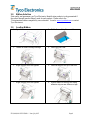
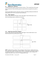
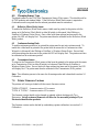
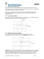
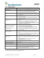
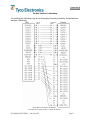
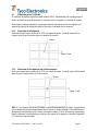
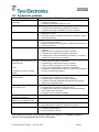
5.1 Alignment For Calibration
Calibration on some products can prove difficult to achieve. This is normally due to the sensor
timing out before the label and backing material contrast has been recognised by the printer’s
sensor.
Reducing the length of time the sensor has to pick up on the difference between the labels and
backing material will result in successful sensor calibrations.
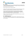
5.1.1 Labels Alignment
Position a label under the T200 sensor with less than approx. 5mm of label travel to occur
before the backing material is picked up by the sensor.
5.1.2 Labels With Sensor Holes Alignment
Position a label under the T200 sensor with less than approx. 5mm of media travel to occur
before the sensor hole is picked up by the sensor.
NOTE: Labels will only calibrate if they pass directly under the sensor. Products that do not
have a label directly under the sensor will not calibrate. A sensor hole or black mark is required
to calibrate these products. If the black mark is to be used the default sensor setting must be
changed in the printer, refer to section 6.0 Changing Sensor Type.
Sensor
Approx 5mm
Sensor
AApprox 5mm
La page charge ...
La page charge ...
La page charge ...
La page charge ...
La page charge ...
La page charge ...
La page charge ...
La page charge ...
La page charge ...
La page charge ...
La page charge ...
La page charge ...
La page charge ...
La page charge ...
La page charge ...
La page charge ...
La page charge ...
La page charge ...
La page charge ...
La page charge ...
La page charge ...
La page charge ...
La page charge ...
La page charge ...
La page charge ...
La page charge ...
La page charge ...
La page charge ...
La page charge ...
La page charge ...
La page charge ...
La page charge ...
La page charge ...
La page charge ...
La page charge ...
La page charge ...
La page charge ...
La page charge ...
La page charge ...
La page charge ...
La page charge ...
La page charge ...
La page charge ...
La page charge ...
La page charge ...
La page charge ...
La page charge ...
La page charge ...
La page charge ...
La page charge ...
La page charge ...
La page charge ...
La page charge ...
La page charge ...
La page charge ...
La page charge ...
La page charge ...
La page charge ...
La page charge ...
La page charge ...
La page charge ...
La page charge ...
La page charge ...
La page charge ...
La page charge ...
La page charge ...
La page charge ...
La page charge ...
La page charge ...
La page charge ...
La page charge ...
La page charge ...
La page charge ...
La page charge ...
La page charge ...
La page charge ...
La page charge ...
La page charge ...
La page charge ...
La page charge ...
La page charge ...
La page charge ...
La page charge ...
La page charge ...
La page charge ...
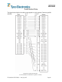
-
 1
1
-
 2
2
-
 3
3
-
 4
4
-
 5
5
-
 6
6
-
 7
7
-
 8
8
-
 9
9
-
 10
10
-
 11
11
-
 12
12
-
 13
13
-
 14
14
-
 15
15
-
 16
16
-
 17
17
-
 18
18
-
 19
19
-
 20
20
-
 21
21
-
 22
22
-
 23
23
-
 24
24
-
 25
25
-
 26
26
-
 27
27
-
 28
28
-
 29
29
-
 30
30
-
 31
31
-
 32
32
-
 33
33
-
 34
34
-
 35
35
-
 36
36
-
 37
37
-
 38
38
-
 39
39
-
 40
40
-
 41
41
-
 42
42
-
 43
43
-
 44
44
-
 45
45
-
 46
46
-
 47
47
-
 48
48
-
 49
49
-
 50
50
-
 51
51
-
 52
52
-
 53
53
-
 54
54
-
 55
55
-
 56
56
-
 57
57
-
 58
58
-
 59
59
-
 60
60
-
 61
61
-
 62
62
-
 63
63
-
 64
64
-
 65
65
-
 66
66
-
 67
67
-
 68
68
-
 69
69
-
 70
70
-
 71
71
-
 72
72
-
 73
73
-
 74
74
-
 75
75
-
 76
76
-
 77
77
-
 78
78
-
 79
79
-
 80
80
-
 81
81
-
 82
82
-
 83
83
-
 84
84
-
 85
85
-
 86
86
-
 87
87
-
 88
88
-
 89
89
-
 90
90
-
 91
91
-
 92
92
-
 93
93
-
 94
94
-
 95
95
-
 96
96
-
 97
97
-
 98
98
-
 99
99
-
 100
100
-
 101
101
-
 102
102
-
 103
103
-
 104
104
-
 105
105


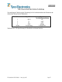
Tyco Electronics T208M-C-PRINTER System User's Manual
- Taper
- System User's Manual
- Ce manuel convient également à
dans d''autres langues
- English: Tyco Electronics T208M-C-PRINTER
- español: Tyco Electronics T208M-C-PRINTER
- Deutsch: Tyco Electronics T208M-C-PRINTER
Autres documents
-
 Red Dot S312BRE Mode d'emploi
-
DeLOCK 82001 Fiche technique
-
 ClosetMaid 1237 Guide d'installation
-
Citizen CLP-631 Guide de démarrage rapide
-
BIXOLON XT2-40 Manuel utilisateur
-
 Tributaries T200 Manuel utilisateur
-
Brady MINIMARK Manuel utilisateur
-
Toshiba B-450-QP SERIES Manuel utilisateur
-
OKI LD640Tn Mode d'emploi
-


