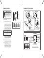
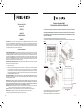
Friedrich KCQ06A10A KCQ08A10A KCQ10A10B KCS08A10A KCS10A10A KCS12A10A KCS12A30A KCS14A10A KCS16A30A KCM14A10A KCM18A30A KCM21A30A KCL24A30B KCL28A30A KCL36A30A KEQ08A11A KES12A33A KES16A33A KEM18A34A KEL24A35B KEL36A35A KHS10A10A KHS12A33A KHM18A34A KHL24A35A Mode d'emploi
- Catégorie
- Climatiseurs split-system
- Taper
- Mode d'emploi

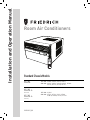
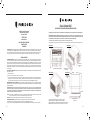
Installation and Operation Manual
SCHEDULE
SYSTEM
FAN SPEED
POWER
FAN MODE
F
SC
AUTO F
ONTINUOU
AN
AUTO
C
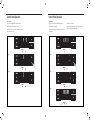
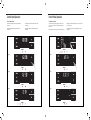
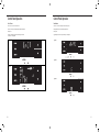
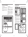
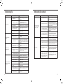
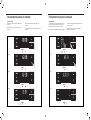
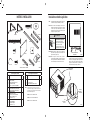
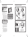
Room Air Conditioners
Standard Chassis Models
Kühl
KCS08, KCS10, KCS12, KCS14
KCS12, KCS16, KCM18, KCM21, KCM24
KCL22, KCL24, KCL28, KCL36
KHS10
KES12, KES16, KH12, KEM18
KHM18, KHM24, KEL36, KHL24
115-Volt:
230-Volt:
Kühl +
Electric Heat
Kühl +
Heat Pump
115-Volt:
230-Volt:
93001015_00

2 3
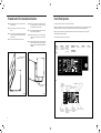
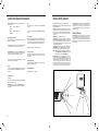
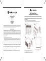
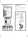
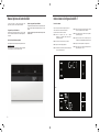
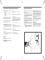
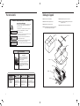
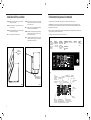
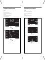
Register your air conditioner
Model information can be found on the name plate
behind the front cover.
Please complete and mail the owner registration
card furnished with this product, or register online
at www.friedrich.com.
For your future convenience, record the model
information here.
MODEL NUMBER
SERIAL NUMBER
PURCHASE DATE
MODEL NUMBER
YS10M10A
SERIAL NUMBER
LICY00008
VOLTS 115
60 HZ / 1 PH
VOLTS MIN 108
COOLING
BTH/HR 6500
EER 12.0
AMPS 8.0
HEATING
BTH/HR 6500
EER 10.4
AMPS 7.0
REFRIGERANT
30.1 OZ R410A
XXXXXXXXX
600 PSIG HS
300 PSIG LS
XXXXXXXXXX
XXXXXXXXX
XXXXXXXXXX
XXXXXXXXXX
FUSE PROTECTED
CIRCUITS USE 15A
TIME DELAY FUSE
X XX
XXXXX
XXXXXXXXXX
U
L
AIR CONDITIONING CO.
SAN ANTONIO, TEXAS
ASSEMBLED IN MEXICO
MODEL NUMBER
YS10M10A
SERIAL NUMBER
LICY00008
AIR CONDITIONING CO.
SAN ANTONIO, TEXAS
ASSEMBLED IN MEXICO
Thank you for your decision to purchase the Friedrich High Efciency Air Conditioner. Your new Friedrich has been carefully engineered and manufactured to
give you many years of dependable, efcient operation, maintaining a comfortable temperature and humidity level. Many extra features have been built into
your unit to assure quiet operation, the greatest circulation of cool, dry air, and the most economic operation.
THANK YOU, on behalf of our entire company,
for making such a wise purchase.
Table of Contents
Safety Precautions ...................................................................................... 4
Unpacking Instructions .................................................................................. 5
WARNING: Before Operating Your Unit ..................................................................... 6
Standard Filter Cleaning / Installation Instructions ........................................................... 7
Premium Carbon Filter Installation Instructions .............................................................. 8
Control Panel Operation .................................................................................. 9
New Kühl Control Options ................................................................................ 22
Wi-Fi Set-Up Instructions ................................................................................ 23
Control Panel Operation Instructions ....................................................................... 24
Remote Control Operation ................................................................................ 25
Remote Effectiveness .................................................................................... 25
Airow Selection and Adjustment .......................................................................... 26
Installation Instructions .................................................................................. 27
Installation Hardware and Accessory Details ................................................................. 28
Standard Window Installation ............................................................................. 29
Cord Routing Change .................................................................................... 38
Thru-the-Wall Installation ................................................................................ 40
Final Inspection & Start-up Checklist ...................................................................... 44
Routine Maintenance .................................................................................... 45
Service and Assistance .................................................................................. 45
Available Accessories .................................................................................... 45
Troubleshooting Tips .................................................................................... 46
Warranty .............................................................................................. 48
Performance Installation & Test Method Addendum .......................................................... 49

4 5
Safety Precautions
Your safety and the safety of others is very
important.
We have provided many important safety messages in this manual and on your
appliance. Always read and obey all safety messages.
This is a safety Alert symbol.
This symbol alerts you to potential hazards that can kill or hurt you and others.
All safety messages will follow the safety alert symbol with the word “WARNING”
or “CAUTION”. These words mean:
Indicates a hazard which, if not avoided, can result in severe personal injury or
death and damage to product or other property.
Indicates a hazard which, if not avoided, can result in personal injury and damage to
product or other property.
All safety messages will tell you what the potential hazard is, tell you how to
reduce the chance of injury, and tell you what will happen if the instructions are
not followed.
Indicates property damage can occur if instructions are not followed.
WARNING
Refrigeration system
under high pressure
Do not puncture, heat, expose to ame or incinerate.
Only certied refrigeration technicians should service
this equipment.
R410A systems operate at higher pressures than R22
equipment. Appropriate safe service and handling
practices must be used.
Only use gauge sets designed for use with R410A.
Do not use standard R22 gauge sets.
NOTICE
CAUTION
WARNING
SAFETY
FIRST
WARNING AVERTISSEMENT ADVERTENCIA
Do not remove, disable or
bypass this unit’s safety
devices. Doing so may cause
re, Doing so may cause re,
injuries, or death.
Ne pas supprime, désactiver ou
contourner cette l´unité des
dispositifs de sécurité, faire vous
risqueriez de provoquer le feu, les
blessures ou la mort.
No eliminar, desactivar o pasar
por alto los dispositivos de
seguridad de la unidad. Si lo hace
podría producirse fuego, lesiones
o muerte.
THINK
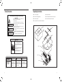
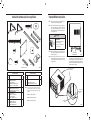
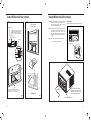
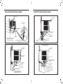
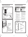
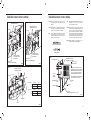
STEP 1. Cut all 4 packing straps.
STEP 2. Remove wooden shipping bar dividers.
STEP 3. Remove top foam pads.
STEP 4. Slowly remove outer box, careful not to loosen decorative front.
STEP 5. Slide the front forward.
STEP 6. Carefully lift decorative front box from foam front support.
STEP 7. Remove decorative front and set safely aside.
STEP 1
STEP 2
STEP 3
STEP 4
STEP 7
STEP 6
STEP 5
STRAPS x4
Unpacking Instructions

6 7
A
WARNING
Electrical Shock Hazard
Make sure your electrical receptacle has the
same conguration as your air conditioner’s
plug. If different, consult a Licensed Electrician.
Do not use plug adapters.
Do not use an extension cord.
Do not remove ground prong.
Always plug into a grounded 3 prong outlet.
Failure to follow these instructions can result
in death, re, or electrical shock.
Make sure the wiring is adequate for your unit.
If you have fuses, they should be of the time delay type. Before you
install or relocate this unit, be sure that the amperage rating of the
circuit breaker or time delay fuse does not exceed the amp rating
listed in Table 1.
DO NOT use an extension cord.
The cord provided will carry the proper amount of electrical power to
the unit; an extension cord may not.
Make sure that the receptacle is compatible with the air
conditioner cord plug provided.
Proper grounding must be maintained at all times. Two prong receptacles
must be replaced with a grounded receptacle by a certied electrician.
The grounded receptacle should meet all national and local codes
and ordinances. You must use the three prong plug furnished with
the air conditioner. Under no circumstances should you remove the
ground prong from the plug.
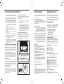
Test the power cord.
All Friedrich room air conditioners are shipped from the factory with
a Leakage Current Detection Interrupter (LCDI) equipped power
cord. The LCDI device on the end of the cord meets the UL and NEC
requirements for cord connected air conditioners.
To test your power supply cord:
1. Plug power supply cord into a grounded 3 prong outlet.
2. Press RESET (see Figure 1).
3. Press TEST, listen for click; the RESET button trips and pops out.
4. Press and release RESET (Listen for click; RESET button latches and
remains in). The power cord is ready for use.
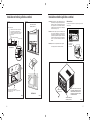
WARNING: Before Operating Your Unit
Figure 1
FRR072
WARNING:
TEST BEFORE EACH USE!
1. PRESS REST BUTTON.
2. PLUG LCDI INTO POWER
RECEPTACLE.
3. PRESS TEST BUTTON,
RESET BUTTON SHOULD
POP UP.
4. PRESS RESET BUTTON
FOR USE.
DO NOT USE IF ABOVE
TEST FAILS.
WHEN GREEN LIGHT
IS ON, IT IS WORKING
PROPERLY!
TEST
RESET
Once plugged in, the unit will operate normally without the need to
reset the LCDI device. If the LCDI device fails to trip when tested
or if the power supply cord is damaged, it must be replaced with a
new power supply cord from the manufacturer. Contact our Technical
Assistance Line at (800) 541-6645. To expedite service, please have
your model number available.
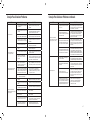
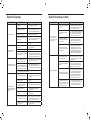
Standard Filter Cleaning / Installation Instructions
Table 1
MODEL
CIRCUIT RATING
OR TIME DELAY
FUSE
REQUIRED
WALL
RECEPTACLE
AMP VOLT
NEMA
NO.
KCS08, KCS10
KCS12, KCS14
KHS10
15 125 5-15R
KCS12, KCS16
KCM18, KCM21
KCL22
15 250 6-15R
KCM24, KCL28
KES12, KES16
KHS12, KCL24
20 250 6-20R
KCL36, KEM18
KEM24, KEL36
KHM18, KHL24
30 250 6-30R
NOTICE
Do not use the LCDI device as an ON/OFF switch.
Failure to adhere to this precaution may cause
premature equipment malfunction.
STEP 1. Swing the door open and remove the lter by grasping the lter
grip and pushing the lter holder upward and outward.
STEP 2. Slide the lter grip out from the lter as shown in Figure 4.
NOTE: Make sure the front frame with the mesh lter is facing you.
Figure 2
Figure 3
FRR052
Figure 4
FRR047
STEP 3. Swing the front frame open. Clean the front frame by washing
the dirt from the lter. Use a mild soap solution if necessary.
Allow lter to dry.
Figure 5
FRR048
STEP 4. Install the lter grip back into the lter by sliding it into the lter.
NOTE: The lter handle slides into the frame in only one direction. If the
tab in the frame stops the handle from sliding in, slide the handle
from the other direction. DO NOT FORCE THE HANDLE INTO
THE FRAME.
STEP 5. Install the lter back into the unit. Follow the instructions on the
inside of the front door.
HANDLE
FILTER GRIP
FILTER GRIP
FILTER
FRONT
FRAME WITH
STANDARD
MESH FILTER
TOP TAB
FRR071

8 9
FRONT
FRAME WITH
MESH FILTER
ALIGN HOLES WITH
PROTRUSION
Premium Carbon Filter Installation Instructions
STEP 4. Place the new carbon lter on the top of the back lter frame.
The carbon lter has been cut to the correct dimension and
should t within the frame as shown in Figure 7.
NOTE: The carbon lter is not a reusable lter, and needs to be replaced
every three months for optimum efciency.
STEP 5. Slide the lter handle back on to hold the frames together
and slide the assembly into the unit as per the instructions
on the door.
NOTE: The lter handle slides into the frame in only one direction. If the
tab in the frame stops the handle from sliding in, slide the handle
from the other direction. DO NOT FORCE THE HANDLE INTO
THE FRAME.
Figure 6
FRR050
STEP 1. Remove the lter from the unit as per the instructions on the
inside of the lter door.
STEP 2. Hold the lter at the top and slide the grip out as shown in
Figure 4.
STEP 3. If you already have a carbon lter installed remove the dirty lter
by laying the lter down and swinging open the front frame as
shown in Figure 6.
NOTE: Make sure the frame with the mesh is facing toward you.
Figure 7
FRR051
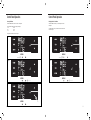
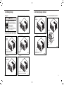
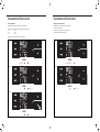
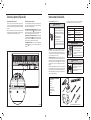
Control Panel Operation
All of the control panel function buttons and mode icons can be viewed in Figure 8.
Power On – Press the button to turn on the air conditioner. The power button illuminates to indicate that the power is on. The backlight on the power switch
will automatically turn off after 20 seconds of inactivity. The remote control can also be used to turn power ON / OFF (see Remote Control).
Display – The display is a high efciency LCD with a built-in backlight. After 20 seconds of inactivity, the display switches off. Touching any button
automatically changes the display to full brightness.
There are three control push buttons on each side of the display.
Figure 8
SYSTEM
Cycles between
AUTO, HEAT,
COOL, or FAN
ONLY
(if equipped)
FAN MODE
Sets fan to either:
- Cycle automatically
- Run continuously
FAN SPEED
Sets fan speed:
LOW, MED,
HIGH or AUTO
(if equipped)
TEMPERATURE
Increment UP
TEMPERATURE
Increment DOWN
TIMER
Turns ON or OFF
IR WINDOW
Do not block
ON / OFF
Turns unit on/ off
MODE
Cycles between
COOL, HEAT, FAN
(if equipped)
ONLY or -AUTO-
CONTROL
LOCKED
-AUTO-
Automatically switches
between cool & heat
WI-FI OPERATING
STATE
TIMER
shows on or off
2 DIGIT DISPLAY
Shows Setting for: Check / clean
FILTER
- Set Point (Temperature)
- Clock (AM/PM)
FA
N
Sets fan to either:
FAN SPEED
Sets fan speed:
LOW, MED, HIGH, OR MAX
(Actual settings are
model dependant)
-
Automatically cycle
- Continuously run
DISCONNECTED
FROM POWER BOARD
COOLHEATFAN ONLY
Figure 9

10 11
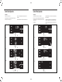
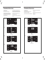
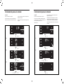
Control Panel Operation
Accessing Sub-Menus
The leftmost MENU button accesses the sub-menu. See Figure 10.
Figure 10
Control Panel Operation
The arrow buttons navigate the 6 menu options (See Figure 11):
– LIM – LOCK
– TM – CnCT
– F-C – diAG
The rightmost button exits the menu. See Figure 12.
MENU
Figure 11
MENU
Figure 12
MENU
Navigating Inside the Sub-Menus
The leftmost MENU button moves you forward through the sub-menu.
See Figure 13.
The rightmost button moves you backward once inside the LIM and TM
menus. See Figure 14.
Figure 13
MENU
Figure 14
MENU

12 13
MENU
MENU
MENU
MENU
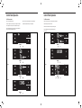
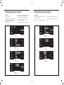
Control Panel OperationControl Panel Operation
The LIM Menu
This is the limit menu. See Figure 15.
Upon entering the menu, the rst option will be to set the lower setpoint
limit using the arrow buttons. See Figure 16.
Figure 15
MENU
Figure 16
MENU
Figure 17
Figure 18
Then you can set the higher setpoint limit using the arrow buttons.
See Figure 17.
Pressing the leftmost button completes the limit setting. See Figure 18.
The TM Menu
This is the TM menu used to set a timer. See Figure 19.
In the menu, you set the current time using the arrow buttons. See Figure
20. (Note: These two “set clock” steps will be skipped if the unit is already
connected to Wi-Fi.)
First, set the hour.
Figure 19
MENU
Figure 20
MENU
Figure 21
Figure 22
Using the leftmost button, you switch to the minutes and complete setting
the time. See Figure 21.
You select your mode. Either cool, heat, or auto. Toggle these using the
arrow buttons. See Figure 22. (Note: cooling-only models skip this step.)
The process is the same for all three modes. Auto mode will be shown as
the example.

14 15
MENU
MENU
MENU
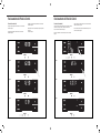
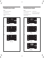
Control Panel Operation
The TM Menu continued
Auto mode selected. See Figure 23.
Set the cool setpoint for your rst timer period using the arrow buttons.
The cooling mode timer only sets the cool setpoint. See Figure 24.
Next, set the heat setpoint for your rst timer period. The heating mode
timer only sets the heat setpoint. See Figure 25.
Figure 23
MENU
Figure 24
MENU
Figure 25
Figure 26
Note: The auto mode timer sets both the cool and heat setpoint.
Set the time to start the rst timer period. See Figure 26.
Control Panel Operation
The TM Menu continued
Set the cool setpoint for the second scheduled timer. See Figure 27.
Set the heat setpoint for the second timer.
Set the time to start the second timer period. See Figure 28.
Press the leftmost button to complete the time timer setup.
See Figure 29.
Figure 27
MENU
Figure 28
Figure 29
MENU

16 17
MENU
Control Panel Operation
The F-C Menu
This menu is used to toggle between Fahrenheit and Celsius.
This is the Fahrenheit/ Celsius Menu. See Figure 30.
Using the arrow buttons on the right side switches it from Fahrenheit to
Celsius. See Figures 31 and 32.
Figure 30
MENU
Figure 31
MENU
Figure 32
Control Panel Operation
The Lock Menu
This menu is used to lock the changing setting with a password.
This is the Lock Menu. See Figure 33.
The default is the off setting. Use the arrows to toggle between off and
on. See Figure 34.
Figure 33
MENU
Figure 34
MENU
Figure 35
MENU
Figure 36
MENU
This is LOCK on. See Figure 35.
Set the rst digit of the password using the arrow buttons. Use the left-
most button to proceed to the next digit. See Figure 36.

18 19
MENU
Control Panel Operation
The Lock Menu continued
Set the second digit of the password using the same method.
See Figure 37.
Set the third digit of the password using the same method.
See Figure 38.
Figure 37
MENU
Figure 38
MENU
Figure 39
Control Panel Operation
The Lock Menu continued
The ON on the right side of the display shows the lock function is
active. To go back into the menu, select the leftmost button again.
See Figure 41.
Enter the password in the same manner it was created. See Figure 42.
Figure 41
MENU
Figure 42
MENU
Figure 43
MENU
Figure 44
MENU
Entering the correct password will give the user access to all of the sub-
menus. See Figure 43.
Accessing the lock menu will allow you to toggle lock OFF if needed.
See Figure 44.
MENU
Figure 40
Set the fourth digit of the password using the same method.
See Figures 39.
Press the leftmost button to complete the password process.
See Figure 40.

20 21
MENU
Control Panel Operation
The CnCT Menu
This menu is used to turn on Wi-Fi connection.
This is the CnCT menu. Pressing the leftmost button will activate Wi-Fi.
See Figure 45.
The Wi-Fi symbol in the top right corner of the display shows Wi-Fi
connection is on. See Figure 46.
Control Panel Operation
The diAG Menu
This menu is used to access the diagnostic codes. See Figure 47.
Selecting this sub-menu shows the E that represents “Error.”
See Figure 48.
Toggle through the error codes using the arrow keys. See Figure 49.
Figure 47
MENU
Figure 48
MENU
Figure 49
Figure 45
MENU
Figure 46
MENU

22 23
New Kühl Control Options
The new Kühl gives you a variety of options for control, programming, and
scheduling including wireless capabilities.
Wireless Programming and Control:
Friedrich Connect allows you to conveniently control, program, and monitor
your air conditioning unit remotely from a smartphone or computer.
Pre-Programmed Timer Options:
Your unit’s digital control comes equipped with a 24-hour timer.
24-Hour Timer
The 24-hour timer allows you to set 2 temperature changes at pre-set times
or a unit control panel.
Customizable Programming Options:
Customizable timers, with up to four temperature adjustments per day, can
be set using Friedrich Connect for one or multiple units.
See www.friedrich.com for complete details on Friedrich Connect.
Wi-Fi Set-Up Instructions
Accessing Sub-Menus:
Below are the set-up instructions for Wi-Fi to use your unit wirelessly.
Follow the instructions below:
STEP 1. Using a mobile device such as a smartphone or laptop, navigate
to www.FriedrichConnect.com.
STEP 2. Sign-in using your username and password.
STEP 3. Click the “Add Device” button.
STEP 4. Select the time zone the device is located in and click the “Next”
button.
STEP 5. To start the setup process click the menu button on the home
screen of your Kühl model.
STEP 6. Using the up and down arrows, navigate to the CnCT screen
(Figure 50).
STEP 7. Click the menu button, this will begin the setup process for your
Friedrich Connect enabled device.
STEP 8. Click the “Next” button on your mobile device.
STEP 9. Follow the on-screen steps to nish adding the device to
your account.
Figure 50
Figure 51

24 25
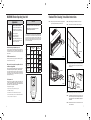
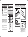
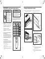
Remote Control - Refer to Figure 52 during operation description.
Getting Started - Install two (2) AAA batteries in the battery compartment
located on the back of the unit.
Operation - The remote control should be within 25 feet of the air conditioner
for operation (refer to Figure 52 for effectiveness). Press the power button
to turn the remote on. The remote will automatically power off after 15
seconds if the buttons are not being pressed. The remote must be on to
control the unit.
POWER Button - Turns remote and unit on and off.
SYSTEM Button - Allows the user to sequentially select the following:
AUTO, COOL, HEAT, and FAN ONLY operations. When the button is
pressed, the display indicates which mode has been selected via a display
message. Note that when the heating function is not available, the system
will automatically skip the HEAT mode.
FAN MODE Button - Selects between automatic (AUTO FAN) or
CONTINUOUS operation. In the AUTO FAN mode, the fan only turns on
and off when the compressor operates or the heat function is enabled.
NOTE: AUTO FAN is not available in the FAN ONLY Mode, the display
indicates CONTINUOUS. In the CONTINUOUS mode, fan speed
is determined by your selection on the FAN SPEED button.
FAN SPEED Button - Used to sequentially select new fan speed,
plus AUTO operation. When the FAN SPEED button is pressed, the
fan speed icon (triangle) changes to indicate the new speed level. Fan
speed automatically varies depending on the set temperature on the
control panel and the actual room temperature. For example, if there
is a big difference between your set temperature and the actual room
temperature, the system fan speed increases to HIGH. It remains at
this speed until the room temperature matches the set temperature.
UP and DOWN Arrows - Pressing either the UP or DOWN button
changes the desired room temperature. The factory preset lower and
upper limits are 60 °F (16 °C) and 99 °F (37 °C). These buttons are also
used to navigate between function options when using the User Menu
or Maintenance Mode.
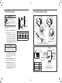
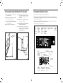
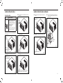
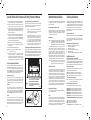
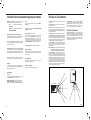
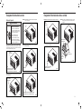
Remote Effectiveness
Handheld Remote - Has an operating range of up to 25 ft. The infrared
remote control signal must have a clear path to transmit the command to
the air conditioning unit. The remote signal has some ability to “bounce”
off of walls and furniture similar to a television remote control. The diagram
below shows the typical operating range of the control in a standard room
with 8 ft high ceilings.
30°
45°
60°
30°
45°
60°
25ft
25ft
8ft
4ft
25ft
16ft
6ft
30°
30°
45°
60°
45°
60°
25ft
25ft
25ft
8ft
25ft
25ft
7.5ft
Figure 52
TOP VIEW
SIDE VIEW
FRR080
Remote Control Operation
SYSTEM - The MODE button allows you to sequentially select up to four
modes of operation:
AUTO Available on select models
COOL
HEAT Available on select models
FAN ONLY
AUTO FAN (No Cooling Demand)
When in AUTO mode, the fan only operates when the system has a
demand to cool or heat the room.
In the ON fan mode, the fan operates all the time. The system periodically
cools or heats the fan’s airow but the ow of air does not stop.
UP and DOWN Arrows - Pressing either an UP or DOWN button changes
the system’s setpoint (desired room temperature). These buttons are also
used to make system parameter changes later in this manual.
One press equals 1 degree of change in Fahrenheit mode. One press
equals 0.5 degree change in Celsius mode.
TIMER
The timer can be engaged or disengaged from the control panel. This is
done by pressing or holding the UP and DOWN arrows simultaneously for
three seconds.
OTHER FUNCTIONS
°F – °C Select
To switch from degrees Fahrenheit (F) to Celsius (C), press the MENU
button and enter the F-C sub-menu.
FAN SPEED - Depending on your model, the FAN SPEED button allows
you to toggle between three or four modes of operation: LOW, MEDIUM,
HIGH and MAX.
Control Panel Operation Instructions
Alerts
When the lter needs to be cleaned or replaced, the CHECK FILTER
icon displays.
The alert can be dismissed by pressing the FAN MODE and TIME for
3 seconds.
Lock Control Panel
To lock/ unlock the front panel controls, navigate to the “LOCK” sub-menu
found after clicking the MENU button. The lock requires a four digit pass code
to lock/ unlock the unit. This pass code will be required to enter the menu to
unlock the unit. The LOCK icon illuminates to indicate the locked status.
The LOCK icon disappears to indicate unlocked status.
External Control Status
The Wi-Fi icon illuminates to indicate that the system is receiving a
Wi-Fi connection. The Wi-Fi icon also provides information about the
signal strength.
ADVANCED FUNCTIONS
The functions mentioned in the following section may or may not be available
depending on the air conditioner model.
Modify the TIMER Function
Navigate to the TIME menu to set the timer.

26 27
IMPORTANT: Before you begin the actual installation of your air
conditioner, check your local electrical codes and the information below.
Your air conditioner must be connected to a power source with the same
alternating current (A.C.) voltage and amperage as marked on the name
plate located on the chassis. Only A.C. can be used. Direct Current (D.C.)
cannot be used.
CIRCUIT PROTECTION – Use on single outlet circuit only. An overloaded
circuit will invariably cause malfunction or failure of an air conditioner;
therefore, it is necessary that the electrical protection is adequate. Due
to momentary high current demand when the air conditioner starts, use a
“TIME DELAY” fuse or a HACR type circuit breaker. Consult your dealer or
power company if in doubt.
Refer to the electrical name plate located on the air conditioner chassis
(see Page 2) to determine the correct fuse or circuit breaker amperage for
your model (see Table 1 on Page 6 for electrical receptacle types).
The power cord has a plug with a grounding prong and a matching
receptacle is required.
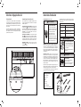
Recommended Tools
1. Power Drill
2.
5
/32" Drill Bit
3. Gloves
4. Carpenters Level
5.
5
/16" Wrench
6.
1
/4" Wrench
7. #2 Phillips Screw Driver
8. Putty Knife or (wood stir stick)
1
2
3
4
65
87
5/16
5/16
1/4
1/4
ITEMS NOT TO SCALE
Installation Instructions
READ THIS FIRST! Electrical Requirements
WARNING
Electrical Shock Hazard
Make sure your electrical receptacle has the
same conguration as your air conditioner’s
plug. If different, consult a Licensed Electrician.
Do not use plug adapters.
Do not use an extension cord.
Do not remove ground prong.
Always plug into a grounded 3 prong outlet.
Failure to follow these instructions can result
in death, re, or electrical shock.
The following instructions are for standard chassis model groups
distinguished by the rst three letters of the model designations cabinet
sizes listed in Table 2.
Table 2
MODEL DESIGNATION CABINET SIZE (H x W x D)
SMALL CHASSIS –
KCS, KES, KHS
15
15
⁄16" x 25
15
⁄16" x 29"
(405 mm x 660 mm x 737 mm)
MEDIUM CHASSIS –
KCM, KEM, KHM
17
15
⁄16" x 25
15
⁄16" x 29"
(455 mm x 660 mm x 737 mm)
LARGE CHASSIS –
KCL, KEL, KHL
20
3
⁄16" x 28" x 35
1
⁄2"
(513 mm x 711 mm x 851 mm)
WARNING
MOVING PARTS HAZARDS
• Do not operate unit out of sleeve or
with front grille removed.
• Do not place hands in blower or fan
blade areas.
Failure to do so can result in serious injury.
CAUTION
Excessive Weight Hazard
Use two or more people when installing your
air conditioner.
Failure to do so can result in back or other
injury.
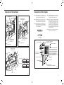
Airflow direction adjustment
The airow path may be adjusted to distribute air independently from the
left or right side of the discharge opening. Each of the banks of louvers can
be directed left, right, up, or down in order to achieve the most optimum
airow positioning.
To adjust airow direction, grab the lever in the center of the louver bank
and move it in the direction that you would like the air to be directed. Please
note that it is normal that airow may be stronger out of one side of the
louvers than the other.
Figure 53
FRR008
Airflow Selection and Adjustment
Fresh air and exhaust control
Your air conditioner has the ability to bring fresh air into the room or exhaust
stale air out of the room. The control slide is found on the upper part of the
unit (see Figure 53).
TO BRING IN FRESH AIR – Move the lever to the Fresh Air position
which allows outside air to enter the room. This is useful in fall and spring
as a means of bringing in fresh outside air when using FAN ONLY. It can
also be used in the summer with the compressor in the Cooling Mode if
you wish.
TO EXHAUST INDOOR AIR – Move the lever to the Exhaust position.
This will allow stale air to be expelled to the outside of the dwelling. This
is especially handy in the spring or fall when indoor air tends to get stale,
or after a social gathering involving smokers, or to remove cooking odors.
BEST PERFORMANCE – Move the lever to the Re-Circulate Position.
This is the most efcient mode for cooling and heating.

28 29
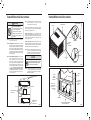
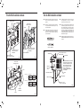
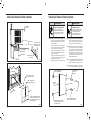
STEP 4. Anchor the side angles (Item 6) by engaging the tabs of the
lower sill plate (see Figure 57, Detail B-2) with the loops of the
side angle. Engage the tabs of the top angle (Item 5) with the top
loops of the side angle (see Figure 57, Detail B-1). Install two (2)
screws (Item 7) to secure the top angle tabs and the side angle
to cabinet (see Figure 57, Detail B-1).
RETAINER SCREWS
AND WASHERS
FAR RIGHT
SCREW
ENTRYGARD
RETAINER
WIRE
Figure 55
FRR012
Figure 54
FRR011
CONTROL UNIT
SUPPORT BRACKET
CAUTION
Handle Use
Use handle on both sides to
pull unit from sleeve.
Do not push, pull, or lift from
center of support.
Use Handle
Locations
(both sides)
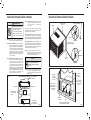
Standard Window Installation
STEP 2. Hold the cabinet stationary. Then, use the hand grips on both
ends of the control unit support bracket to pull the chassis out of
the cabinet (see Figure 55).
STEP 3. Remove the large white foam blocks used to restrain the
compressor during shipment (see Figure 56). Inspect base pan
for dislodged white foam blocks and remove. Do not remove
any other foam parts.
NOTE: Hardware and accessories used during installation are shown
on Page 28. Each part will be referred as “Item No.”
STEP 1. Remove the chassis EntryGard
™
retainer by removing the far
right screw (see Figure 54). Save this screw to reattach the
chassis retainer after installation (Step 12). Also, remove and
discard the two retainer screws and washer located at the rear
of the unit (see Figure 54).
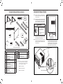
Window Mount
Installation Hardware
ITEM
NO
DESCRIPTION QTY.
8
9
10
11
WINGBOARD MOUNTING PARTS
WINGBOARD (MASONITE)
“J” TYPE SPEED NUT
WINGBOARD CLIP (SPRING STEEL)
SCREW, #8 x ½″ PHILLIPS TRUSS HD.
1
4
4
4
12
13
WINDOW SEALING
WINDOW SEAL GASKET (DARK FOAM)
CHASSIS SEAL GASKET (LIGHT FOAM)
1
1
1
2
3
4
SHELL MOUNTING PARTS
SUPPORT BRACKET
SCREW, 10-24 x 1″ HEX HEAD
10-24 FLAT WELD NUT
SCREW, SHEET METAL #12 x 2″
2
4
4
7
5
6
7
WINGBOARD ANGLE MOUNTING
WINGBOARD ANGLE, TOP
WINGBOARD ANGLE, SIDE
SCREW, SHEET METAL #8 x
3
/8″
1
2
2
Thru-the-Wall
Installation Hardware
ITEM
NO
DESCRIPTION QTY.
4
14
MOUNTING PARTS
SCREW, SHEET METAL #12A x 2″
CHASSIS SEAL GASKET (LIGHT FOAM)
7
1
NOTE: Kühl + models do not come with window mounting
components. When mounting a cooling and heating
model, a window installation kit must be purchased
separately.
KWIKS – For all KES and KH models.
KWIKM – For all KEM and KHM models.
KWIKL – For all KEL and KHL models.
ITEM 1
ITEM 2
ITEM 3
ITEM 4
ITEM 7
ITEM 10 ITEM 11
ITEM 5
ITEM 8
ITEM 12 ITEM 13
ITEM 14
ITEM 9
ITEM 6
ITEMS NOT TO SCALE
FRR009
Installation Hardware and Accessory Details

30 31
Figure 57
FRR013
Figure 58
FRR014
Figure 56
FRR045
EVAPORATOR COIL
TOP VIEW OF UNIT
REMOVE AND DISCARD
SCREWS
RIGHT SIDELEFT SIDE
BACK
FRONT
REMOVE AND SAVE
SCREW FOR
RE-INSTALLATION
COMPRESSOR FAN MOTOR
REMOVE AND DISCARD
FOAM BLOCKS
Standard Window Installation continued
CAUTION
Remove Shipping Blocks
Prior to operating the unit remove
the foam shipping blocks.
Failure to do so may result in
damage to the unit which is not
covered by the manufacturer’s
warranty!
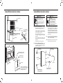
STEP 5. Check the window sill and frame to be sure they are in
good condition and functioning.
STEP 6. CABINET MOUNTING – Raise the lower window
1
/4″ more than
the height of the cabinet. Carefully slide the cabinet through
the opening until the lower sill plate channel rests behind the
window sill and the top angle rests against the window (see
Figure 58). Center the cabinet within the opening. Drill three (3)
5
/32″ diameter pilot holes into window sill using the holes in the
cabinet sill plate as a guide. Install three (3) #12 x 2″ long screws
(Item 4) (see Figure 58).
STEP 7. OUTSIDE SUPPORT MOUNTING – Refer to Figures 57
and 58. Assemble the support brackets (Item 1) to the
bottom of the cabinet with four (4) 10-24 1″ long screws
(Item 2) and four 10-24 flat nuts (Item 3). Adjust the support
brackets, using a combination of the elongated holes of the
bracket and different hole locations in the cabinet, to bring
the bottom support bracket pads in contact with the wall. A
1″ x 4″ or 2″ x 4″ SPACER SHOULD BE USED BETWEEN THE
WALL AND SUPPORT THE BRACKETS WHEN INSTALLED
ON ALUMINUM OR VINYL SIDING. Drill
5
/32″ diameter pilot
holes and secure the brackets to the wall with two (2) 12A
x 2″ long screws (Item 4).
NOTE: DO NOT LEVEL the cabinet from front-to-back. Make sure
there is approximately a
3
/8″ to
1
/2″ slope (
1
/8 to
1
/4 bubble
on level) toward the outside of the house.
Adjust the support brackets to provide an inside-to-outside slope for
excess condensation drainage (refer to Standard Window Installation,
Figures 59 through 61). Tighten all screws.
Alternate support method A: If you have a deep window sill which
prevents you from mounting the brackets as shown in Figure 61, try the
following: Using the elongated holes and different hole locations in the
cabinet, set the placement of the bracket to support the unit’s weight
(Figure 62). Tighten all screws.
Alternate support method B: If the window ledge gap is narrow, try the
following. Bend the bracket end tab at. Cut the bracket in two (2) places
as shown in Figure 63. Bend the short piece so it will be vertical when
installed. Adjust the placement as required. Tighten all screws.
STEP 8. Measure and cut the wingboard panels (t with about
1
/8″
clearance) from the supplied Masonite (Item 8) to t the space
between the window side channels and cabinet (Figure 64).
Make sure you include the depth of the window channel.
NOTICE
For YOUR security and safety, YOU must
provide a means of preventing the upper
part of the window from opening.
STEP 9. To assemble the wingboard panels, push on the “J” type speed
nuts (Item 9) and spring steel clips (Item 10) (see Figure 65
on Page 35). Secure each panel with two (2) screws (Item 11).
Refer to Figure 66 on Page 36.
Standard Window Installation continued
CABINET
TOP ANGLE (ITEM 5)
SILL PLATE
TAB
#8 x
3
/8″ LONG SCREW
(ITEM 7) 2 REQUIRED
TAB
SIDE ANGLE
(ITEM 6)
2 REQUIRED
DETAIL B-2
DETAIL B-1
TAB
LOOP
CENTER
CABINET
IN WINDOW
SIDE TO SIDE
DRILL (3)
5
/32″ DIA.
PILOT HOLES AND
INSTALL (3) #12 x 2″
LONG SCREWS
(ITEM 4)
WINDOW SILL
LOCATE SILL PLATE GUIDE CHANNEL
JUST BACK OF WINDOW SILL
TOP ANGLE
(ITEM 5)
PULL WINDOW
SASH DOWN
BEHIND TOP
ANGLE
SIDE ANGLE
(ITEM 6)

32 33
Figure 61
FRR017
Figure 62
FRR018
Figure 59
FRR015
FRR016
Figure 60
FOR LEDGES
ALTERNATE METHOD A
Standard Window Installation continuedStandard Window Installation continued
#10-24 SCREW
3
/8″ SLOPE DOWN
#12 x 2″ SHEET METAL
SCREW (ITEM 4)
CONDENSER
AIR INLETS
#10-24 FLAT WELD NUT
SPACER
ADJUST IN OR OUT TO REST
ON THE LEDGE
STONE LEDGE
#10-24 FLAT WELD NUT
SECURE THE LONGEST SIDE OF
THE BRACKET TO THE SHELL
3
/8″ SLOPE DOWN
#10-24 SCREW
STRAIGHTEN TAB TO LAY FLAT
ALONG THE BOTTOM RAIL OF
THE SHELL
STONE LEDGE
SPACER SHOULD BE USED BETWEEN
WALL AND BRACKET WHEN INSTALLED
ON ALUMINUM OR VINYL SIDING.
3
/8″ SLOPE DOWN
#12 x 2″ SCREW
(ITEM 4)
#10-24 x 1″ HEX HEAD
SCREW (ITEM 2)
SUPPORT BRACKET
(ITEM 1)
SUPPORT
BRACKET
(ITEM 1)
10-24 x FLAT WELD
NUT (ITEM 3)
SPACER SHOULD BE USED BETWEEN
WALL AND BRACKET WHEN INSTALLED
ON ALUMINUM OR VINYL SIDING.
#10-24 FLAT WELD NUT
#12 x 2″ SHEET METAL
SCREW (ITEM 4)
3
/8″ SLOPE DOWN
CONDENSER
AIR OUTLET
CONDENSER
AIR INLETS
#10-24 SCREW

34 35
Figure 65
FRR021
Standard Window Installation continued
Figure 63
FRR019
Figure 64
FRR020
Standard Window Installation continued
ALTERNATE METHOD B
STEP 10. INSTALL THE R1 INSULATION PANEL – To minimize air
leaks and ensure optimal insulation, install the included R1
insulation panel (14 in parts list) (see Figure 67A-C).
First, measure the width from one side of the cabinet/ sleeve
(covering the side angles where the wingboard was just secured)
to the end of the wingboard (see Figure 67A).
Next, cut the R1 insulation panel to the measured width and
remove protective cover, exposing adhesive on back panel
(see Figure 67B).
Last, evenly apply the adhesive side of the panel across the
entire height and width from side angle to wingboard panel
(see Figure 67C).
Repeat the steps above for the other wingboard panel.
STEP 11. INSTALL THE WINDOW SEALING GASKETS – Measure
and cut the dark foam window seal gasket (Item 12) and
install it between the upper glass panel and the top part of
the window sash (see Figure 67A).
STEP 12. Carefully team lift the chassis and set it into the cabinet. Slide
the chassis stopping approximately 3″ from full insertion. Insert
the chassis seal gasket (Item 13) one inch deep between the
chassis and the cabinet (see Figure 68) as shown on Page 37.
A paint stir stick or ruler might be helpful here. Begin inserting
the gasket at either bottom corner and go up the side, across the
top, and down the opposite side. Then push the chassis all the
way into the cabinet.
NOTE: If the chassis seal gasket is not installed or installed improperly,
the operation of the unit will be negatively affected. Operational
noise and outside noise will also amplied.
STEP 13. Reattach the EntryGard
™
chassis and EntryGard
™
retainer wire
with the same screw retained in Step 1 (see Figure 54).
CAUTION
Cut/Sever
Although great care has been
taken to minimize sharp edges
in the construction of your unit,
use gloves or other hand
protection when handling unit
Failure to do so can result in minor
to moderate personal injury.
WARNING
Falling Object Hazard
Not following Installation Instructions
for mounting your air conditioner can
result in property damage, injury, or
death.
ROTATED 90°
SPRING STEEL CLIP
(ITEM 10) 2 REQUIRED
SLIDE CLIP OVER CUT EDGE
OF WINGBOARD PANEL
CUT EDGE
CENTER THE HOLE IN THE
SPEED NUT OVER THE SLOT
IN THE WINGBOARD PANEL
CUT
WINGBOARD
PANEL
“J” TYPE SPEED NUT
(ITEM #9) 2 REQUIRED
3″
3″
#10-24 FLAT WELD NUT
3
/8″ SLOPE DOWN
OUTSIDE WALL
#10-24 SCREW
CUT TO FIT DIMENSION “A”
AND BEND DOWN TO FORM
A VERTICAL LEG.
DIMENSION “A”
STONE LEDGE
CUT HERE
DISCARD
SHADED AREA
A
SUBTRACT
1
/8″ FROM DIMENSION “B” AND
MEASURE FROM THE EDGE OF WINGBOARD
(ITEM 8), MARK, SCORE AND CUT WITH
APPROPRIATE CUTTING TOOL.
MEASURE DISTANCE “B” TO INSIDE
OF THE CHANNEL ON EACH SIDE.
CUT HERE AND DISCARD
CENTER WASTE MATERIAL
WINGBOARD
B
B
B
B

36 37
Figure 68
FRR024
B
Figure 69
FRR053
LOCATION OF GRILLE
REMOVAL TOOL
OPTIONAL: The factory assembles the supply cord so that it exits the left
side of the unit at the bottom. At the consumer’s discretion, pull
the supply cord taut through the loops (refer to Cord Routing
Change, Figure 70) and route the cord down.
STEP 14. To attach and prevent damage to the front grille, align the cord
notch over the cord and center the fresh air lever, then align
and tighten the four (4) captive screws as indicated by the
arrows in Figure 69. Before closing the front panel, be sure
the lter is in place. Make sure curtains do not block the side
air intakes.
STEP 15. Refer to the Control Panel Operation section for instructions.
You are now to control the comfort level of the room.
Use Tool Provided
Please use the provided tool to attach the decorative front to the chassis.
USE HAND TOOLS
DO NOT
OVERTIGHTEN
Standard Window Installation continued
A
A
WINDOW JAM
TOP OF CABINET
PLACE WINGBOARD PANEL IN WINDOW JAM
TO COMPRESS THE SPRINGS INSIDE THE
RUNNERS, AND SWING THE WINGBOARD
PANELS INTO PLACE AS INDICATED BY THE
DASHED LINES.
CLIP (ITEM 10)
SECTION A-A
SECURE THE SIDE WINGBOARD PANELS TO
THE SIDE ANGLES WITH FOUR (4) #8 x
1
/2" LONG
SCREWS (ITEM 11), TWO ON EACH SIDE.
Figure 66
FRR022
Figure 67
Standard Window Installation continued
POWER CORD CLIP
CHASSIS SEAL GASKET (ITEM 13)
NOTE: WHEN INSTALLING THE CHASSIS
SEAL GASKET, BEGIN AT EITHER BOTTOM
CORNER AND GO UP THE SIDE & ACROSS
THE TOP & DOWN THE OPPOSITE SIDE.
SECTION B-B
C
B
A
INSERT FOAM WINDOW
SEAL GASKET (ITEM 12)
FRR023

38 39
Figure 75
FRR059
ELECTRICAL
CONTROL PANEL
Figure 76
FRR060
ELECTRICAL CONTROL PANEL SCREWS (3)
(RETAINED FROM STEP 1)
Figure 77
FRR061
CORD RETAINER
CLIPS
FRONT
GRILLE
POWER
CORD
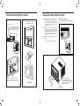
STEP 19. Carefully push electrical control panel back into chassis.
STEP 20. Reinstall the 3 screws removed earlier to secure electrical
control panel.
STEP 21. If running power cord to the right of the unit, install the cord into
the cord retainer clips along the bottom front of the unit.
Cord Routing Change continued
Figure 71
FRR055
ELECTRICAL CONTROL
PANEL SCREWS (3)
Remove the 3 screws as shown from the electrical control panel.
Save to reinstall later.
Figure 70
FRR054
ELECTRICAL
CONTROL
PANEL
NOTE:
DECORATIVE FRONT
REMOVAL USE TOOL PROVIDED.
(SEE FIGURE 69 FOR LOCATION OF TOOL)
Figure 72
FRR056
1 INCH
90°
Figure 73
FRR057
ELECTRICAL CORD
STRAIN RELIEF
Figure 74
FRR058
ENSURE THE ELECTRICAL CORD STRAIN RELIEF IS FLUSH
WITH THE TOP OF ELECTRICAL CONTROL PANEL.
Cord Routing Change
WARNING
Electrical Shock Hazard
Make sure your electrical receptacle has the
same configuration as your air conditioner’s
plug. If different, consult a Licensed Electrician.
Do not use plug adapters.
Do not use an extension cord.
Do not remove ground prong.
Always plug into a grounded 3 prong oulet.
Failure to follow these instructions can result in
death, fire, or electrical shock.
For convenience and optimum appearance, the direction that the power
cord exits the unit may be changed from left to right by following the
procedure below. Select the exit location on the left or right based on
proximity to the power outlet.
STEP 16. Carefully pull out electrical control panel 1″, but not all the way.
STEP 17. Pull electrical cord strain relief downward until free and rotate
90 degrees to the right.
STEP 18. Push electrical cord strain relief back upward into the electrical
control panel.
Unplug unit.
La page est en cours de chargement...
La page est en cours de chargement...
La page est en cours de chargement...
La page est en cours de chargement...
La page est en cours de chargement...
La page est en cours de chargement...
La page est en cours de chargement...
La page est en cours de chargement...
La page est en cours de chargement...
La page est en cours de chargement...
La page est en cours de chargement...
La page est en cours de chargement...
La page est en cours de chargement...
La page est en cours de chargement...
La page est en cours de chargement...
La page est en cours de chargement...
La page est en cours de chargement...
La page est en cours de chargement...
La page est en cours de chargement...
La page est en cours de chargement...
La page est en cours de chargement...
La page est en cours de chargement...
La page est en cours de chargement...
La page est en cours de chargement...
La page est en cours de chargement...
La page est en cours de chargement...
La page est en cours de chargement...
La page est en cours de chargement...
La page est en cours de chargement...
La page est en cours de chargement...
La page est en cours de chargement...
La page est en cours de chargement...
La page est en cours de chargement...
La page est en cours de chargement...
La page est en cours de chargement...
La page est en cours de chargement...
La page est en cours de chargement...
La page est en cours de chargement...
La page est en cours de chargement...
La page est en cours de chargement...
La page est en cours de chargement...
La page est en cours de chargement...
La page est en cours de chargement...
La page est en cours de chargement...
La page est en cours de chargement...
La page est en cours de chargement...
La page est en cours de chargement...
La page est en cours de chargement...
La page est en cours de chargement...
La page est en cours de chargement...
La page est en cours de chargement...
La page est en cours de chargement...
La page est en cours de chargement...
La page est en cours de chargement...
La page est en cours de chargement...
La page est en cours de chargement...
La page est en cours de chargement...
La page est en cours de chargement...
La page est en cours de chargement...
La page est en cours de chargement...
La page est en cours de chargement...
-
 1
1
-
 2
2
-
 3
3
-
 4
4
-
 5
5
-
 6
6
-
 7
7
-
 8
8
-
 9
9
-
 10
10
-
 11
11
-
 12
12
-
 13
13
-
 14
14
-
 15
15
-
 16
16
-
 17
17
-
 18
18
-
 19
19
-
 20
20
-
 21
21
-
 22
22
-
 23
23
-
 24
24
-
 25
25
-
 26
26
-
 27
27
-
 28
28
-
 29
29
-
 30
30
-
 31
31
-
 32
32
-
 33
33
-
 34
34
-
 35
35
-
 36
36
-
 37
37
-
 38
38
-
 39
39
-
 40
40
-
 41
41
-
 42
42
-
 43
43
-
 44
44
-
 45
45
-
 46
46
-
 47
47
-
 48
48
-
 49
49
-
 50
50
-
 51
51
-
 52
52
-
 53
53
-
 54
54
-
 55
55
-
 56
56
-
 57
57
-
 58
58
-
 59
59
-
 60
60
-
 61
61
-
 62
62
-
 63
63
-
 64
64
-
 65
65
-
 66
66
-
 67
67
-
 68
68
-
 69
69
-
 70
70
-
 71
71
-
 72
72
-
 73
73
-
 74
74
-
 75
75
-
 76
76
-
 77
77
-
 78
78
-
 79
79
-
 80
80
-
 81
81


Friedrich KCQ06A10A KCQ08A10A KCQ10A10B KCS08A10A KCS10A10A KCS12A10A KCS12A30A KCS14A10A KCS16A30A KCM14A10A KCM18A30A KCM21A30A KCL24A30B KCL28A30A KCL36A30A KEQ08A11A KES12A33A KES16A33A KEM18A34A KEL24A35B KEL36A35A KHS10A10A KHS12A33A KHM18A34A KHL24A35A Mode d'emploi
- Catégorie
- Climatiseurs split-system
- Taper
- Mode d'emploi
dans d''autres langues
- English: Friedrich KCQ06A10A KCQ08A10A KCQ10A10B KCS08A10A KCS10A10A KCS12A10A KCS12A30A KCS14A10A KCS16A30A KCM14A10A KCM18A30A KCM21A30A KCL24A30B KCL28A30A KCL36A30A KEQ08A11A KES12A33A KES16A33A KEM18A34A KEL24A35B KEL36A35A KHS10A10A KHS12A33A KHM18A34A KHL24A35A Operating instructions
- español: Friedrich KCQ06A10A KCQ08A10A KCQ10A10B KCS08A10A KCS10A10A KCS12A10A KCS12A30A KCS14A10A KCS16A30A KCM14A10A KCM18A30A KCM21A30A KCL24A30B KCL28A30A KCL36A30A KEQ08A11A KES12A33A KES16A33A KEM18A34A KEL24A35B KEL36A35A KHS10A10A KHS12A33A KHM18A34A KHL24A35A Instrucciones de operación
Documents connexes
-
Friedrich KCQ05A10A Guide d'installation
-
Friedrich WCT08A10A WCT10A10A WCT10A30A WCT12A10A WCT12A30A WCT16A30A WET10A33A WET12A33A WET16A33A WHT12A33A Mode d'emploi
-
-
-
-
-
-
-
-
Autres documents
-
 North Storm NS-12W-WAC WIFI Operating Instructions Manual
-
TCL TWC-08CR/UH Guide d'installation
-
Windmere WWF2600 Mode d'emploi
-
-
 Movincool CPK24 Guide d'installation
-
 Prime-Line TH 21937 Mode d'emploi
-
 Caframo 760CA-WBX Manuel utilisateur
-
 Movincool CPK24 Guide d'installation
-
 Movincool CPK24 Guide d'installation
-
Accu-Tech 8980L-VFR Manuel utilisateur


