Team Losi LOS03022T2 Le manuel du propriétaire
- Catégorie
- Jouets
- Taper
- Le manuel du propriétaire
Ce manuel convient également à

Before operating this vehicle, please read all printed materials thoroughly.
Horizon Hobby is not responsible for inadvertent errors in this manual.
INSTRUCTION MANUAL
BEDIENUNGSANLEITUNG
MANUEL D’UTILISATION
MANUALE DI ISTRUZIONI
Battery and Charger
Battery and Charger
Not Included
Not Included

EN
2
22S SCT RTR: 1:10 2WD SHORT COURSE TRUCK • INSTRUCTION MANUAL
2
22S SCT RTR: 1:10 2WD SHORT COURSE TRUCK • INSTRUCTION MANUAL
WARNING: Read the ENTIRE instruction manual to become familiar with the features of the product before operating. Failure to operate the product correctly can result in damage
to the product, personal property and cause serious injury.
This is a sophisticated hobby product. It must be operated with caution and common sense and requires some basic mechanical ability. Failure to operate this Product in a safe and respon-
sible manner could result in injury or damage to the product or other property. This product is not intended for use by children without direct adult supervision. Do not use with incompat-
ible components or alter this product in any way outside of the instructions provided by Horizon Hobby, LLC. This manual contains instructions for safety, operation and maintenance. It is
essential to read and follow all the instructions and warnings in the manual, prior to assembly, setup or use, in order to operate correctly and avoid damage or serious injury.
NOTICE
All instructions, warranties and other collateral documents are subject to change at the sole discretion of Horizon Hobby, LLC.
For up-to-date product literature, visit horizonhobby.com and click on the support tab for this product.
MEANING OF SPECIAL LANGUAGE
The following terms are used throughout the product literature to indicate various levels of potential harm when operating this product:
WARNING: Procedures, which if not properly followed, create the probability of property damage, collateral damage, and serious injury OR create a high probability of superfi cial injury.
CAUTION: Procedures, which if not properly followed, create the probability of physical property damage AND a possibility of serious injury.
NOTICE: Procedures, which if not properly followed, create a possibility of physical property damage AND a little or no possibility of injury.
Age Recommendation: Not for children under 14 years. This is not a toy.
REGISTER YOUR LOSI PRODUCT ONLINE
Register your vehicle now and be the fi rst to fi nd out about the latest option parts, product
updates and more. Click on the Support tab at WWW.LOSI.COM and follow the product
registration link to stay connected.
As the user of this product, you are solely responsible for operating in a manner that does not
endanger yourself and others or result in damage to the product or property of others.
This model is controlled by a radio signal subject to interference from many sources outside
your control. This interference can cause momentary loss of control, so it is advisable to
always keep a safe distance in all directions around your model as this margin will help avoid
collisions or injury.
• Never operate your model with low transmitter batteries.
• Always operate your model in open spaces away from full-size vehicles, traffi c and people.
• Never operate the model in the street or in populated areas for any reason.
• Carefully follow the directions and warnings for this and any optional support equipment
(chargers, rechargeable battery packs, etc.) you use.
• Keep all chemicals, small parts and anything electrical out of the reach of children.
• Never lick or place any portion of the model in your mouth as it could cause serious injury
or even death.
• Exercise caution when using tools and sharp instruments.
• Take care during maintenance as some parts may have sharp edges.
• Immediately after using your model, do NOT touch equipment such as the motor, electronic
speed control and battery, because they generate high temperatures. You may burn
yourself seriously touching them.
• Do not put fi ngers or any objects inside rotating and moving parts, as this may cause
damage or serious injury.
• Always turn on your transmitter before you turn on the receiver in the car. Always turn off
the receiver before turning your transmitter off.
• Keep the wheels of the model off the ground when checking the operation of the radio
equipment.
SAFETY PRECAUTIONS AND WARNINGS
TABLE OF CONTENTS
REGISTER YOUR LOSI PRODUCT ONLINE .................................................................2
BOX CONTENTS ........................................................................................................3
COMPONENTS ..................................................................................................................3
WATER-RESISTANT VEHICLE WITH WATERPROOF ELECTRONICS ..............................3
GENERAL PRECAUTIONS ...................................................................................................3
WET CONDITIONS MAINTENANCE ....................................................................................3
QUICK START ............................................................................................................3
CHARGING THE BATTERY .........................................................................................3
INSTALLING THE BATTERY ........................................................................................4
SPEKTRUM STX2 RADIO SYSTEM .............................................................................4
INSTALLING THE TRANSMITTER BATTERIES ........................................................................4
SRX200 RECEIVER ....................................................................................................4
DRIVING PRECAUTIONS ..........................................................................................5
POWERING ON THE VEHICLE ....................................................................................5
BEFORE RUNNING YOUR VEHICLE ............................................................................5
RUN TIME .................................................................................................................6
TO IMPROVE RUN TIMES ...................................................................................................6
PERFORMING A CONTROL DIRECTION TEST.............................................................6
CHANGING THE TRAVEL ADJUST SETTINGS .............................................................6
DYNAMITE® WP 60A FWD/REV BRUSHED ESC (DYNS2210) ....................................6
SPECIFICATIONS ...............................................................................................................6
ESC LED STATUS ...............................................................................................................6
MOTOR TO ESC CONNECTION ...........................................................................................6
ESC CALIBRATION PROCEDURE ........................................................................................6
ESC FUNCTIONS AND MODES ...........................................................................................6
ESC PROGRAMMING PROCEDURE ....................................................................................7
DESCRIPTIONS ..................................................................................................................7
DYNAMITE
®
12-TURN 550 BRUSHED MOTOR (DYNS1222).......................................8
PRECAUTIONS ..................................................................................................................8
GEARING .........................................................................................................................8
CHANGING THE PINION GEAR/GEAR RATIO ......................................................................8
SETTING THE GEAR MESH .................................................................................................8
TROUBLESHOOTING GUIDE ......................................................................................8
LIMITED WARRANTY ...........................................................................................8–9
WARRANTY AND SERVICE CONTACT INFORMATION ................................................9
FCC STATEMENT .......................................................................................................9
IC INFORMATION .....................................................................................................9
COMPLIANCE INFORMATION FOR THE EUROPEAN UNION ......................................9
REPLACEMENT PARTS ............................................................................................35
RECOMMENDED PARTS..........................................................................................35
OPTIONAL PARTS ...................................................................................................35
EXPLODED VIEW ..............................................................................................36–39

3
EN
22S SCT RTR: 1:10 2WD SHORT COURSE TRUCK • INSTRUCTION MANUAL
3
22S SCT RTR: 1:10 2WD SHORT COURSE TRUCK • INSTRUCTION MANUAL
2.4GHZ DIGITAL
RADIO SYSTEM
BOX CONTENTS
Your new Horizon Hobby vehicle has been designed and built with a combination of
waterproof and water-resistant components to allow you to operate the product in many
“wet conditions,” including puddles, creeks, wet grass, snow and even rain.
While the entire vehicle is highly water-resistant, it is not completely waterproof and your
vehicle should NOT be treated like a submarine. The various electronic components used in
the vehicle, such as the Electronic Speed Control (ESC), servo(s) and receiver are waterproof,
however, most of the mechanical components are water-resistant and should not be
submerged.
Metal parts, including the bearings, hinge pins, screws and nuts, as well as the contacts
in the electrical cables, will be susceptible to corrosion if additional maintenance is not
performed after running in wet conditions. To maximize the long-term performance of your
vehicle and to keep the warranty intact, the procedures described in the “Wet Conditions
Maintenance” section below must be performed regularly if you choose to run in wet
conditions. If you are not willing to perform the additional care and maintenance
required, then you should not operate the vehicle in those conditions.
CAUTION: Failure to exercise caution while using this product and
complying with the following precautions could result in product malfunction
and/or void the warranty.
GENERAL PRECAUTIONS
• Read through the wet conditions maintenance procedures and make sure that you
have all the tools you will need to properly maintain your vehicle.
• Not all batteries can be used in wet conditions. Consult the battery manufacturer before
use. Caution should be taken when using Li-Po batteries in wet conditions.
• Most transmitters are not water-resistant. Consult your transmitter’s manual or the
manufacturer before operation.
• Never operate your transmitter or vehicle where lightning may be present.
• Do not operate your vehicle where it could come in contact with salt water (ocean
water or water on salt-covered roads), contaminated or polluted water. Salt water
is very conductive and highly corrosive, so use caution.
• Even minimal water contact can reduce the life of your motor if it has not been certifi ed
as water-resistant or waterproof. If the motor becomes excessively wet, apply very light
throttle until the water is mostly removed from the motor. Running a wet motor at high
speeds may rapidly damage the motor.
• Driving in wet conditions can reduce the life of the motor. The additional resistance of
operating in water causes excess strain. Alter the gear ratio by using a smaller pinion or larger
spur gear. This will increase torque (and motor life) when running in mud, deeper puddles, or
any wet conditions that will increase the load on the motor for an extended period of time.
WET CONDITIONS MAINTENANCE
• Drain any water that has collected in the tires by spinning them at high speed. With the
body removed, place the vehicle upside down and pull full throttle for a few short bursts
until the water has been removed.
CAUTION: Always keep hands, fi ngers, tools and any loose or hanging
objects away from rotating parts when performing the above drying
technique.
• Remove the battery pack(s) and dry the contacts. If you have an air compressor or a can of
compressed air, blow out any water that may be inside the recessed connector housing.
• Remove the tires/wheels from the vehicle and gently rinse the mud and dirt off with a
garden hose. Avoid rinsing the bearings and transmission.
NOTICE: Never use a pressure washer to clean your vehicle.
• Use an air compressor or a can of compressed air to dry the vehicle and help remove any
water that may have gotten into small crevices or corners.
• Spray the bearings, drive train, fasteners and other metal parts with a water-displacing
light oil. Do not spray the motor.
• Let the vehicle air dry before you store it. Water (and oil) may continue to drip for a few
hours.
• Increase the frequency of disassembly, inspection and lubrication of the following:
- Front and rear axle hub assembly bearings.
- All transmission cases, gears and differentials.
- Motor—clean with an aerosol motor cleaner and re-oil the bushings
with lightweight motor oil.
WATER-RESISTANT VEHICLE WITH WATERPROOF ELECTRONICS
QUICK START
Please read the entire manual to gain a full understanding of the 22S RTR vehicle, fi ne-tuning the setup and performing maintenance.
1. Read the safety precautions found in this manual.
2. Charge a battery for the vehicle. Refer to your charger's instruction manual
for charging information and warnings.
3. Install the AA batteries in the transmitter. Only use alkaline
or rechargeable batteries.
4. Install the fully charged battery in the vehicle.
5. Power ON the transmitter and then the vehicle. Wait 5 seconds for the ESC to
initialize. Always power the transmitter ON before the vehicle and power it
OFF after the vehicle has been powered OFF.
6. Check the steering and throttle control directions. Verify that the servos are
moving in the correct direction.
7. Drive your vehicle.
8. Power OFF the vehicle and then the transmitter.
9. Unplug the battery and remove it from the vehicle.
10. Perform any necessary maintenance.
CHARGING THE BATTERY
COMPONENTS
• Losi
®
22S SCT™ RTR: 1/10-Scale 2WD Short Course Truck
• Spektrum™
STX2
®
2-CH 2.4GHz FHSS Transmitter (SPMSTX200)
• Spektrum™
6KG Waterproof Servo (SPMS606)
• Spektrum™ SRX200 2-CH Receiver (SPMSRX200)
• Dynamite
®
12-Turn 550 Brushed Motor (DYNS1222)
• Dynamite
®
60A WP Brushed ESC (DYNS2210)
• 4 AA batteries (for transmitter)
Choose a battery designed to work with the Dynamite
®
60A WP Brushed ESC. We recommend
the Dynamite
®
7.4 5000mAh 2S 50C LiPo: Hardcase with EC3™ connector (DYNB33802EC).
Choose a charger designed to charge 2S batteries.
We recommend the Dynamite
®
Prophet™ Sport Li-Po 35W AC Battery Charger (DYNC2005CA).
Refer to your battery and charger manuals for usage, safety, and charging information.

EN
4
22S SCT RTR: 1:10 2WD SHORT COURSE TRUCK • INSTRUCTION MANUAL
4
22S SCT RTR: 1:10 2WD SHORT COURSE TRUCK • INSTRUCTION MANUAL
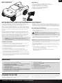
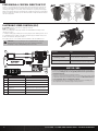
INSTALLING THE BATTERY
1. Ensure the ESC is powered OFF.
2. Rotate the battery hatch lock to align the fl at section with the edge of the battery hatch.
3. Open the battery hatch.
4. Install the fully charged battery in the vehicle.
5. Close the battery hatch and rotate the lock fully to secure the hatch.
6. Connect the battery to the ESC noting the correct polarity.
7. Power ON the transmitter, then the vehicle.
INSTALLING TRANSMITTER BATTERIES
This transmitter requires 4 AA batteries.
1. Remove the battery cover from the transmitter.
2. Install the batteries as shown.
3. Install the battery cover.
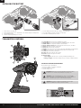
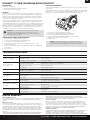
TRANSMITTER CONTROLS
2.4GHZ DIGITAL
RADIO SYSTEM
1
2
11
1. Steering Wheel Controls direction (left/right) of the model
2. Throttle Trigger Controls speed and direction (forward/brake/reverse) of the model
3. ON/OFF Switch Turns the power ON/OFF for the transmitter
4. Throttle Limiting Switch Adjusts the throttle limit from 50%, 75%, and 100%
5. TH Rate Adjusts the end point of the throttle
6. TH Trim Adjusts the throttle neutral point
7. TH REV Reverses the function of the speed control when pulled back or pushed forward
8. ST REV Reverses the function of the steering when the wheel is turned left or right
9. ST Trim Adjusts the steering center point
10. ST Rate Adjusts the end point of the steering
11. Antenna Transmits the signal to the model
12. Indicator Lights
Solid red lights—indicates radio connectivity and adequate battery power
Flashing red lights—indicates the battery voltage is critically low. Replace batteries
3
4
8
7
9
6
10
5
12
CAUTION: NEVER remove the transmitter batteries while the model is
powered on. Loss of model control, damage or injury may occur.
CAUTION: If using rechargeable batteries, charge only rechargeable
batteries. Charging non-rechargeable batteries may cause the batteries to
burst, resulting in injury to persons and/or damage to property.
CAUTION: Risk of explosion if battery is replaced by an incorrect type.
Dispose of used batteries according to state and local laws.

5
EN
22S SCT RTR: 1:10 2WD SHORT COURSE TRUCK • INSTRUCTION MANUAL
5
22S SCT RTR: 1:10 2WD SHORT COURSE TRUCK • INSTRUCTION MANUAL
DRIVING PRECAUTIONS
• Maintain sight of the vehicle at all times.
• Routinely inspect the vehicle for loose wheel hardware.
• Routinely inspect the steering assembly for any loose hardware. Driving the vehicle
off-road can cause fasteners to loosen over time.
• Do not drive the vehicle in tall grass. Doing so can damage the vehicle or electronics.
• Stop driving the vehicle when you notice a lack of power. Driving the vehicle when
the battery is discharged can cause the receiver to power off. If the receiver loses power,
you will lose control of the vehicle. Damage due to an over-discharged Li-Po battery is
not covered under warranty.
CAUTION: Do not discharge a Li-Po battery below 3V per cell. Batteries
discharged to a voltage lower than the lowest approved voltage may become
damaged, resulting in loss of performance and potential fi re when batteries
are charged.
• Do not apply forward or reverse throttle if the vehicle is stuck.
Applying throttle in this instance can damage the motor or ESC.
• After driving the vehicle, allow the electronics to cool before driving the vehicle again.
IMPORTANT: Keep wires away from all moving parts.
POWERING ON THE VEHICLE
1. Center the ST TRIM and TH TRIM dials on the transmitter.
2. Power on the transmitter.
3. Install a fully charged battery pack per the Installing the Battery section.
4. Power on the ESC.
BEFORE RUNNING YOUR VEHICLE
1. Check for free suspension movement. All suspension arms and steering components
should move freely. Any binds will cause the vehicle to handle poorly.
Tip: To increase the ride height and ground clearance of your vehicle, install the included
shock spacers.
2. Charge a battery pack. Always charge the battery pack as per the battery and/or
charger manufacturers’ instructions.
3. Set the transmitter steering trim. Follow the instructions to set the steering trim/subtrim
so that the vehicle drives straight with no input to the steering.
4. Perform a Control Direction Test.
RUN TIME
The largest factor in run time is the capacity of the battery pack. A larger mAh rating
increases the amount of run time experienced.
The condition of a battery pack is also an important factor in both run time and speed.
The battery connectors may become hot during driving. Batteries will lose performance
and capacity over time.
Driving the vehicle from a stop to full speed repeatedly will damage the batteries
and electronics over time. Sudden acceleration will also lead to shorter run times.
TO IMPROVE RUN TIMES
• Keep your vehicle clean and well maintained.
• Allow more airfl ow to the ESC and motor.
• Change the gearing to a lower ratio. A lower ratio decreases the operating temperature
of the electronics. Use a smaller pinion gear or larger spur gear to lower the gear ratio.
• Use a battery pack with a higher mAh rating.
• Use the optimum charger to charge battery packs (Visit your local hobby dealer for
more information).
BINDING
Binding is the process of programming the receiver to recognize the GUID (Globally Unique
Identifi er) code of a single specifi c transmitter. The STX2
®
transmitter and SPMSRX200
receiver are bound at the factory. If you need to rebind, follow the instructions below.
1. With the vehicle on a fl at, level surface, insert the Bind Plug in the BIND port on the
receiver.
2. Connect a fully charged battery pack to the ESC.
3. Power on the ESC. The red LED fl ashes, indicating the receiver is in bind mode.
4. Center the ST TRIM and TH TRIM dials on the transmitter.
5. Turn the steering wheel to Full Right. Power the transmitter on while holding the steering
wheel to the Right.
6. Release the steering wheel when the receiver LED stops fl ashing.
7. Remove the Bind Plug, then power off the receiver to save the settings.
8. Power off the transmitter.
9. Remove the bind plug and store it in a convenient place.
You must rebind when:
• Different failsafe positions are desired e.g., when throttle or steering reversing has been
changed.
• Binding the receiver to a different transmitter.
CHANGING THE THROTTLE LIMIT
Beginner Mode
Throttle Limiting Switch: 50%
• Best for learning the basic functions of left, right, stop, brake and reverse
• For use in smaller areas
• Longest battery life
Medium Speed
Throttle Limiting Switch: 75%
• Great top speed and acceleration
• Easier to accelerate in desired direction, especially on loose surfaces when compared to
Maximum Speed setup
• Run time is greatly increased over Maximum Speed setup with an impact to top speed
Maximum Speed (Default)
Throttle Limiting Switch: 100%
• Higher top speeds and maximum acceleration
Throttle Limit Switch

EN
6
22S SCT RTR: 1:10 2WD SHORT COURSE TRUCK • INSTRUCTION MANUAL
EN
6
22S SCT RTR: 1:10 2WD SHORT COURSE TRUCK • INSTRUCTION MANUAL
PERFORMING A CONTROL DIRECTION TEST
Perform a control test with the vehicle wheels off the ground. If the wheels rotate after the
vehicle is powered ON, adjust the TH Trim knob until they stop. To make the wheels move
forward, pull the trigger. To reverse them, wait for the wheels to stop, then push the trigger.
When moving forward, the wheels should maintain a straight line without any steering wheel
input. If not, adjust the ST Trim knob, so the wheels maintain a straight line without having to
turn the steering wheel.
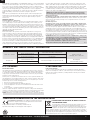
ELECTRONIC SPEED CONTROL (ESC)
Part # Description
A DYNS1222 Motor
B DYN9005EC* Battery 7.4V
C SPMS606 Waterproof Steering Servo
D SPMSRX200 Receiver
E DYNS2210 Waterproof Electronic Speed Control (ESC)
F Channel 1
G Channel 2
* Not Included
Operation Tone
Start up One short tone, followed by one long tone.
Low Voltage Cut-Off
When low voltage cuttoff is reached, the vehicle
will slow and emit a continuous tone.
Low Voltage at Start Up
When a low battery is plugged in and powered on,
the vehicle will emit two low tones and power off.
EC3EC3
A
B
C
D
E
G
F
Programming: The ESC comes with one jumper pre-installed:
BATT: Li-Po confi guration.
The throttle setting without the jumper indicates Throttle/Brake/Reverse. Always use this
setting for this vehicle.
To change the battery type to NiMH, disconnect the jumper from the default port and connect
it to the NiMH port. If the jumper is removed from the BATT port, the default setting is Li-Po
mode. Power off the ESC, then power it back on.
If the jumpers are lost or not installed, the ESC will default to REV: ON and BATT: Li-Po.
WARNING: Only use the NiMH port when using NiMH batteries. Using the
NiMH port with a Li-Po battery can cause serious damage to the battery.
Attempting to charge a damaged battery may result in a fi re.
*
• Seat the motor brushes by driving smoothly on a fl at surface during use of the fi rst
battery charge. Failing to do so can greatly reduce motor performance
and functional life.
• Prolong motor life by preventing overheating conditions.
Undue motor wear results from frequent turns, stops and starts, pushing objects, driving
in deep water and tall grass, and driving continuously up hill. Allow the motor to
cool completely before running the vehicle.
• Over-temperature protection is installed on the ESC to prevent circuit damage, but
cannot protect the motor from driving against heavy resistance.
MOTOR CARE

7
EN
22S SCT RTR: 1:10 2WD SHORT COURSE TRUCK • INSTRUCTION MANUAL
7
22S SCT RTR: 1:10 2WD SHORT COURSE TRUCK • INSTRUCTION MANUAL
PRECAUTIONS
• Never touch moving parts.
• Never disassemble while the batteries are installed.
• Always let parts cool before touching.
GEARING
The 22S SCT includes two pinion gears for different running conditions. The installed 14T
pinion is for running on dirt or other loose surfaces, and driving with lots of stopping and
starting. For driving on hard paved surfaces, and longer speed runs, install the included
18T pinion gear for higher top speeds. Keep in mind that running with the 14T pinion will
increase motor life compared to the 18T pinion.
Installing a pinion gear with fewer teeth or a spur gear with more teeth will increase torque
and reduce top speed. Likewise, a pinion gear with more teeth or a spur gear with fewer
teeth will reduce torque and increase top speed. Take care when installing larger pinion gears
as this can “overgear” the vehicle, resulting in an overheated motor and ESC. When testing
different gearing options, pay close attention to the temperature of the motor and speed
control to ensure you are operating within the correct temperature range. If the motor is too
hot, switch to a lower pinion gear and/or higher spur gear combination.
CAUTION: Do not touch the ESC or motor after use or personal injury
may result. Do not allow the ESC or motor to exceed 160°F (71°C). A
temperature gun (recommended DYNF1055) can be used to safely monitor
the temperature before handling.
CHANGING THE PINION GEAR/GEAR RATIO
1. Remove the screws holding the gear cover in place.
2. Loosen the set screw and remove the installed pinion gear.
3. Loosen the motor screws and slide the motor back.
4. Place the new pinion on the end of the motor shaft so the set screw is located
over the fl at on the shaft.
5. Position it so the teeth line up with the spur gear and secure the pinion by tightening
the set screw.
6. Set the gear mesh.
DYNAMITE
®
12-TURN 550 BRUSHED MOTOR (DYNS1222)
SETTING THE GEAR MESH
The gear mesh has already been set at the factory. Setting it is only necessary when changing
motors or gears.
Proper gear mesh (how gear teeth meet) is important to the performance of the vehicle. When
the gear mesh is too loose, the spur gear could be damaged by the pinion gear of the motor. If
the mesh is too tight, speed could be limited and the motor and ESC will overheat.
1. Loosen the motor screws and slide the motor back.
2. Put a small piece of paper between the pinion and spur gears.
3. Push the gears together while tightening the motor screws.
4. Remove the paper. Check the mesh at 3–5 different locations around
the spur gear for a small amount of movement.
5. Install gear cover.
NOTICE: For running on street surfaces, or for speed runs, install the
included 18T pinion gear. For running on loose dirt, or other rough terrain
surfaces with stopping and starting, keep the installed 14T pinion gear in
use.
TROUBLESHOOTING GUIDE
PROBLEM POSSIBLE CAUSE SOLUTION
Vehicle does not operate
Battery not charged or plugged in Charge battery/plug in
ESC switch not “ON” Turn on ESC switch
Transmitter not “ON” or low battery Turn on/replace batteries
Motor runs but wheels
do not rotate
Pinion not meshing with spur gear Adjust pinion/spur mesh
Pinion spinning on motor shaft Tighten pinion gear setscrew on motor shaft fl at spot
Transmission gears stripped Replace transmission gears
Drive pin broken Check and replace drive pin
Steering does not work
Servo plug not in receiver properly Make sure the steering servo plug is connected to the receiver steering channel, noting proper polarity
Servo gears or motor damaged Replace or repair servo
Will not turn one direction Servo gears damaged Replace or repair servo
Motor does not run
Motor wire solder joint is damaged Resolder the motor wire with the proper equipment
Motor wire broken Repair or replace as needed
ESC damaged Contact Horizon Hobby Product Support
ESC gets hot
Motor over-geared Use smaller pinion or larger spur gear
Driveline bound up Check wheels and transmission for binding
Poor run time and/or sluggish
acceleration
Battery pack not fully charged Recharge battery
Charger not allowing full charge Try another charger
Driveline bound up Check wheels, transmission for binding
Poor range and/or glitching
Transmitter batteries low Check and replace
Vehicle battery low Recharge battery
Loose plugs or wires Check all wire connections and plugs
LIMITED WARRANTY
What this Warranty Covers
Horizon Hobby, LLC, (Horizon) warrants to the original purchaser that the product purchased
(the “Product”) will be free from defects in materials and workmanship at the date of
purchase.
What is Not Covered
This warranty is not transferable and does not cover (i) cosmetic damage, (ii) damage due
to acts of God, accident, misuse, abuse, negligence, commercial use, or due to improper use,
installation, operation or maintenance, (iii) modifi cation of or to any part of the Product,
(iv) attempted service by anyone other than a Horizon Hobby authorized service center, (v)
Product not purchased from an authorized Horizon dealer, or (vi) Product not compliant
with applicable technical regulations or (vii) use that violates any applicable laws, rules, or
regulations.
OTHER THAN THE EXPRESS WARRANTY ABOVE, HORIZON MAKES NO OTHER WARRANTY
OR REPRESENTATION, AND HEREBY DISCLAIMS ANY AND ALL IMPLIED WARRANTIES,
INCLUDING, WITHOUT LIMITATION, THE IMPLIED WARRANTIES OF NON-INFRINGEMENT,
MERCHANTABILITY AND FITNESS FOR A PARTICULAR PURPOSE. THE PURCHASER
ACKNOWLEDGES THAT THEY ALONE HAVE DETERMINED THAT THE PRODUCT WILL SUITABLY
MEET THE REQUIREMENTS OF THE PURCHASER’S INTENDED USE.
Purchaser’s Remedy
Horizon’s sole obligation and purchaser’s sole and exclusive remedy shall be that Horizon
will, at its option, either (i) service, or (ii) replace, any Product determined by Horizon to be
defective. Horizon reserves the right to inspect any and all Product(s) involved in a warranty
claim. Service or replacement decisions are at the sole discretion of Horizon. Proof of purchase
is required for all warranty claims. SERVICE OR REPLACEMENT AS PROVIDED UNDER THIS
WARRANTY IS THE PURCHASER’S SOLE AND EXCLUSIVE REMEDY.
Limitation of Liability
HORIZON SHALL NOT BE LIABLE FOR SPECIAL, INDIRECT, INCIDENTAL OR CONSEQUENTIAL
DAMAGES, LOSS OF PROFITS OR PRODUCTION OR COMMERCIAL LOSS IN ANY WAY,
REGARDLESS OF WHETHER SUCH CLAIM IS BASED IN CONTRACT, WARRANTY, TORT,
NEGLIGENCE, STRICT LIABILITY OR ANY OTHER THEORY OF LIABILITY, EVEN IF HORIZON HAS

EN
8
22S SCT RTR: 1:10 2WD SHORT COURSE TRUCK • INSTRUCTION MANUAL
8
22S SCT RTR: 1:10 2WD SHORT COURSE TRUCK • INSTRUCTION MANUAL
EU Compliance Statement: Horizon Hobby, LLC hereby declares that this
product is in compliance with the essential requirements and other relevant
provisions of the RED and EMC Directive.
A copy of the EU Declaration of Conformity is available online at:
http://www.horizonhobby.com/content/support-render-compliance.
INSTRUCTIONS FOR DISPOSAL OF WEEE BY USERS IN
THE EUROPEAN UNION
This product must not be disposed of with other waste. Instead, it is the user’s
responsibility to dispose of their waste equipment by handing it over to a
designated collections point for the recycling of waste electrical and electronic
equipment. The separate collection and recycling of your waste equipment at
the time of disposal will help to conserve natural resources and ensure that it is recycled in a
manner that protects human health and the environment. For more information about where
you can drop off your waste equipment for recycling, please contact your local city offi ce, your
household waste disposal service or where you purchased the product.
Country of Purchase Horizon Hobby Contact Information Address
United States of America
Horizon Service Center
(Repairs and Repair Requests)
servicecenter.horizonhobby.com/RequestForm/
2904 Research Road
Champaign, Illinois 61822 USA*
Horizon Product Support
(Product Technical Assistance)
productsupport@horizonhobby.com
877-504-0233
Sales websales@horizonhobby.com 800-338-4639
European Union
Horizon Technischer Service
service@horizonhobby.eu +49 (0) 4121 2655 100
Hanskampring 9
D 22885 Barsbüttel, GermanySales: Horizon Hobby GmbH
WARRANTY AND SERVICE CONTACT INFORMATION
FCC STATEMENT
FCC ID: 2AI3D-SS0001
This equipment has been tested and found to comply with the limits for Part 15 of the FCC
rules. These limits are designed to provide reasonable protection against harmful interference
in a residential installation. This equipment generates uses and can radiate radio frequency
energy and, if not installed and used in accordance with the instructions, may cause harmful
interference to radio communications.
However, there is no guarantee that interference will not occur in a particular installation. If
this equipment does cause harmful interference to radio or television reception, which can be
determined by turning the equipment off and on, the user is encouraged to try to correct the
interference by one or more of the following measures:
• Reorient or relocate the receiving antenna.
• Increase the separation between the equipment and receiver.
• Connect the equipment to an outlet on a circuit different from that to which the receiver
is connected.
• Consult the dealer or an experienced radio/TV technician for help.
This device complies with part 15 of the FCC rules. Operation is subject to the following two
conditions: (1) This device may not cause harmful interference, and (2) this device must accept
any interference received, including interference that may cause undesired operation.
NOTICE: Modifi cations to this product will void the user’s authority to operate this equipment.
IC INFORMATION
IC ID: 21682-SSTC9202
This device complies with Industry Canada licence-exempt RSS standard(s). Operation is
subject to the following two conditions: (1) this device may not cause interference, and (2)
this device must accept any interference, including interference that may cause undesired
operation of the device.
BEEN ADVISED OF THE POSSIBILITY OF SUCH DAMAGES. Further, in no event shall the liability
of Horizon exceed the individual price of the Product on which liability is asserted. As Horizon
has no control over use, setup, fi nal assembly, modifi cation or misuse, no liability shall be
assumed nor accepted for any resulting damage or injury. By the act of use, setup or assembly,
the user accepts all resulting liability. If you as the purchaser or user are not prepared to
accept the liability associated with the use of the Product, purchaser is advised to return the
Product immediately in new and unused condition to the place of purchase.
Law
These terms are governed by Illinois law (without regard to confl ict of law principals). This
warranty gives you specifi c legal rights, and you may also have other rights which vary from
state to state. Horizon reserves the right to change or modify this warranty at any time
without notice.
WARRANTY SERVICES
Questions, Assistance, and Services
Your local hobby store and/or place of purchase cannot provide warranty support or service.
Once assembly, setup or use of the Product has been started, you must contact your local
distributor or Horizon directly. This will enable Horizon to better answer your questions and
service you in the event that you may need any assistance. For questions or assistance, please
visit our website at www.horizonhobby.com, submit a Product Support Inquiry, or call the toll
free telephone number referenced in the Warranty and Service Contact Information section to
speak with a Product Support representative.
Inspection or Services
If this Product needs to be inspected or serviced and is compliant in the country you live
and use the Product in, please use the Horizon Online Service Request submission process
found on our website or call Horizon to obtain a Return Merchandise Authorization (RMA)
number. Pack the Product securely using a shipping carton. Please note that original boxes
may be included, but are not designed to withstand the rigors of shipping without additional
protection. Ship via a carrier that provides tracking and insurance for lost or damaged parcels,
as Horizon is not responsible for merchandise until it arrives and is accepted at our facility.
An Online Service Request is available at http://www.horizonhobby.com/content/service-
center_render-service-center. If you do not have internet access, please contact Horizon
Product Support to obtain a RMA number along with instructions for submitting your product
for service. When calling Horizon, you will be asked to provide your complete name, street
address, email address and phone number where you can be reached during business hours.
When sending product into Horizon, please include your RMA number, a list of the included
items, and a brief summary of the problem. A copy of your original sales receipt must be
included for warranty consideration. Be sure your name, address, and RMA number are clearly
written on the outside of the shipping carton.
NOTICE: Do not ship Li-Po batteries to Horizon. If you have any issue with a
Li-Po battery, please contact the appropriate Horizon Product Support offi ce.
Warranty Requirements
For Warranty consideration, you must include your original sales receipt verifying
the proof-of-purchase date. Provided warranty conditions have been met, your Product
will be serviced or replaced free of charge. Service or replacement decisions are at the sole
discretion of Horizon.
Non-Warranty Service
Should your service not be covered by warranty, service will be completed and
payment will be required without notifi cation or estimate of the expense unless
the expense exceeds 50% of the retail purchase cost. By submitting the item for
service you are agreeing to payment of the service without notifi cation. Service estimates are
available upon request. You must include this request with your item submitted for service.
Non-warranty service estimates will be billed a minimum of ½ hour of labor. In addition you
will be billed for return freight. Horizon accepts money orders and cashier’s checks, as well as
Visa, MasterCard, American Express, and Discover cards. By submitting any item to Horizon for
service, you are agreeing to Horizon’s Terms and Conditions found on our website http://www.
horizonhobby.com/content/service-center_render-service-center.
ATTENTION: Horizon service is limited to Product compliant in the country of use
and ownership. If received, a non-compliant Product will not be serviced. Further,
the sender will be responsible for arranging return shipment of the
un-serviced Product, through a carrier of the sender’s choice and at the sender’s
expense. Horizon will hold non-compliant Product for a period of
60 days from notifi cation, after which it will be discarded. 10/15
COMPLIANCE INFORMATION FOR THE EUROPEAN UNION
*For the most up-to-date customer service contact information, please visit: www.horizonhobby.com/content/service-center-render-service-center

30
22S SCT RTR: 1:10 2WD SHORT COURSE TRUCK • INSTRUCTION MANUAL
Part # English Deutsch Français Italiano
DYNS1222 DYN 550 12-Turn Brushed Motor DYN-550-12-Gang-Bürstenmotor Motore con spazzole 12 giri DYN 550 Moteur à balais DYN 550 12T
DYNS2210 60A FWD/REV Brushed ESC 60A Vorwärts/Rückwärts Bürstenregler
Variateur 60A Marche Av/Arr pour moteur à
charbon
60A FWD/REV regolatore a spazzole
LOS230060 Kicker Audio Body Set: 22S SCT Kicker-Audio-Gehäusesatz: 22S SCT Kit corpo audio: 22S SCT
Ensemble de carrosserie Kicker Audio: 22S
SCT
LOS230061 Magnafl ow Body Set: 22S SCT Magnafl ow-Gehäusesatz: 22S SCT Kit carrozzeria Magnafl ow: 22S SCT Ensemble de carrosserie Magnafl ow: 22S SCT
LOS231034 Mud Flaps Schmutzfänger Bavettes de garde-boue Parafanghi
LOS231042 Chassis Fahrgestell Châssis Telaio
LOS231043 Composite Steering Set Komposit-Lenkungssatz Ensemble de direction composite Set sterzo in composito
LOS231044 Chassis Mounting Set Fahrgestellstützsatz Support châssis Set supporto telaio
LOS231045 Bulkhead Camber Black, Servo Mount Spritzwandsturz schwarz, Servohalterung Support de suspension, noir, support du servo Paratia camber nero, supporto servo
LOS231046 Steering Hardware Set Hardwaresatz Lenkung Ensemble de matériel de direction Set bulloneria sterzo
LOS231047 Body Mount Set Karosseriehalterungssatz Support de carrosserie Set Supporto Carrozzeria
LOS231048 Front Bumper Set Frontstoßstangensatz Pare-choc avant Set paraurti anteriore
LOS231049 Rear Bumper Set Heckstoßstangensatz Pare-choc arrière Set paraurti posteriore
LOS231050 Steering Bearing Set Lenklagersatz Ensemble de roulement de direction Set cuscinetti sterzo
LOS231051 Battery Mounting Foams Schaumstoffe Akku-Halterung Mousses de montage de batteries Schiuma di montaggio per batteria
LOS232036 Gear Cover and Motor Guard Getriebeabdeckung und Motorschutz Cache de l’engrenage et protection moteur Coperchio pignone e protezione motore
LOS232037 Transmission Case Getriebeabdeckung Boîtier de transmission Scatola del cambio
LOS232038 Spur Gear and Slipper Pad 48P 84T Stirnrad und Gleitkissen 48P 84T
Engrenage cylindrique et sabot de piston 48P
84T
Corona e pattino scorrevole 48P 84T
LOS232039 Complete Gear Differential Komplettes Getriebe Differential Engrenage différentiel complet Differenziale pignone completo
LOS232040 Gear Set, Gear Differential Getriebesatz, Getriebe Differential Ensemble d’engrenages, engrenage différentiel Set pignone, differenziale pignone
LOS232041 Motor Plate Motorplatte Plaque moteur Piastra motore
LOS232042 Idler Gear and Shaft Zwischenrad und Welle Axe de pignon intermédiaire Ingranaggio e albero folle
LOS232043 Layshaft and Gear Zwischenwelle und Getriebe Arbre intermédiaire et engrenage Albero secondario e ingranaggio
LOS232044 Front Axle Vorderachse Essieu avant Assale anteriore
LOS232045 CVA Driveshaft, Complete CVA-Antriebswelle, komplett Arbres de transmission CVA, complet Albero di trasmissione CVA completo
LOS232046 Gear Differential Rebuild Set Nachbausatz Getriebe Differential
Ensemble de reconstruction de l’engrenage
différentiel
Set differenziale pignone rigenerato
LOS232047 Slipper Hardware Set Hardwaresatz Gleiter Ensemble de matériel du sabot Set bulloneria scorrevole
LOS232048 Wheel Hex Set Radsechskantsatz (4) Hexagones de roues (4) Set esagoni ruote (4)
LOS233016 Front Shock Set, Complete Kompletter Vorderer Stoßdämpfersatz Lot d’amortisseurs avant, complet Set ammortizzatore anteriore completo
LOS233017 Rear Shock Set, Complete Kompletter Hinterer Stoßdämpfersatz Lot d’amortisseurs arrière, complet Set ammortizzatore posteriore completo
LOS233018 Shock Body Set Stoßdämpfergehäusesatz Carrosserie amortisseurs Set corpo ammortizzatore
LOS233019 Shock Shaft Set Kolbenstangensatz Lot de bras d’amortisseurs Set albero ammortizzatore
LOS233020 Spring Set Federsatz Ressort Set molle
LOS233021 Spring Cups and Clip Set Satz mit Federtellern und Clips Lot de coupelles de ressort et d’attaches Set molle, coppe e clip
LOS233022 Shock Seal Set Stoßdämpferdichtungssatz Lot de joints d’amortisseurs Set guarnizioni ammortizzatore
LOS233023 Shock Caps (2) Stoßdämpferkappen (2) Capuchons d’amortisseurs (2) Tappi ammortizzatore (2)
LOS233024 Shock Ends Stoßdämpferenden Extrémités d’amortisseurs Terminali ammortizzatore
LOS234024 Suspension Arm Set Aufhängungsarmsatz Lot de bras de suspension Set braccetti sospensioni
LOS234025 Front Caster Block Set Vorderradblocksatz Lot de blocs de roulettes avant Set blocco ruota anteriore
LOS234026 Hub and Spindle Set Satz aus Nabe und Spindel Lot de moyeux et de fusées Set mozzo e fuselli
LOS234027 Camber and Steering Link Set Satz aus Sturz und Lenkstange Lot de timonerie de direction et de la chambre Set camber e braccetti sterzo
LOS234028 Shock Tower Set Stossdämpfersatz Support d’amortisseurs Set Torre Ammortizzatore
LOS234029 Pivot Set Drehgelenksatz Lot pivot Set perni
LOS234030 Aluminum Front Chassis Plate Vordere Aluminium-Karosserieplatte Plaque châssis avant en aluminium Piastra anteriore telaio in alluminio
LOS234031 Aluminum Rear Chassis Plate Hintere Aluminium-Karosserieplatte Plaque châssis arrière en aluminium Piastra posteriore telaio in alluminio
LOS234032 Hinge Pin Set Scharnierbolzensatz Lot de charnière Set piastrine per perni
LOS234033 Hinge Pin Lock Screws Scharnierbolzen-Sicherungsstifte Vis de blocage de charnière Viti di supporto piastrine per perni
LOS234034 Ball Stud, 4.8mm x 6mm (4) Kugelzapfen, 4,8mm x 6mm (4) Piton à rotule, 4,8mm x 6mm (4) Viti a sfera, 4,8 mm x 6 mm (4)
LOS235003 Cap Head Screws M3 x 6mm (10) Inbusschrauben M3 x 6mm (10) Vis à tête bombée, M3 x 6mm (10) Viti a testa cilindrica, M3 x 6 mm (10)
LOS235018 Set Screws, M3 X 3mm (10) Stellschrauben, M3 x 3mm (10) Vis de fi xation, M3 x 3mm (10) Viti di fermo, M3 x 3 mm (10)
LOS235024 Button Head Screws M3 x 25mm (10) Halbrundschrauben, M3 x 25mm (10) Vis à tête bombée M3 x 25mm (10) Viti a testa tonda, M3 x 25 mm (10)
LOS235028 Flat Head Screws M3 x 45mm (6) Flachkopfschrauben, M3 x 45mm (6) Vis à tête fraisée, M3 x 45mm (6) Viti a testa piatta, M3 x 45 mm (6)
LOS235029 Cap Head Screws M2 x 4mm (10) Inbusschrauben M2 x 4mm (10) Vis à tête bombée, M2 x 4mm (10) Viti a testa cilindrica, M2 x 4 mm (10)
LOS4114 48 Pitch Pinion Gear,14T 48 Pitchzahnradgetriebe, 14T Engrenage à pignons pas 48, 14T Pignone 48P, 14T
LOS4118 48 Pitch Pinion Gear,18T 48 Pitchzahnradgetriebe, 18T Engrenage à pignons pas 48, 18T Pignone 48P, 18T
LOS43015 Wheel and Tire Mounted (2) Montiertes Rad und Reifen (2) Support volant et pneu (2) Ruota con pneumatico montato (2)
LOSA6937 5 x 10mm Shielded Ball Bearing (2) 5 x 10mm abgedichtetes Kugellager (2) Roulement à billes blindé 5 x 10mm (2) Cuscinetti a sfera schermati 5 x 10 mm (2)
LOSA6955 5 x 13mm HD Clutch Bearings (2) 5 x 13mm HD Kupplungslager (2)
Roulements à embrayage ultra-résistant 5 x
13mm (2)
Cuscinetti frizione HD 5 x 13mm (2)
LOSA6957 10 x 15 x 4mm BB (2) w/ Nylon Retainer 10 x 15 x 4mm BB (2) mit Nylon-Halter
Roulements à billes 10 x 15 x 4mm (0) avec
bague de retenue en nylon
Cuscinetto a sfera 10 x 15 x 4mm (2) con
fermo in nylon
SPMS606 Standard, WP, Plastic Gear Servo Standard, WP, Kunststoffgetriebe-Servo Standard, WP, Servo ingranaggio in plastica
Standard, étanche, Servo à engrenage en
plastique
SPMSRX200 STX2 2CH Radio STX2 2-Kanal Fernsteuerung Émetteur STX2 2 voies Trasmittente STX2 2 canali
SPMSTX200 2-Ch Receiver 2 Kanal Empfänger Récepteur 2 voies Ricevitore
TLR235004 Flat Head Screws, M3 x 25mm (10) Flachkopfschrauben, M3 x 25mm (10) Vis à tête fraisée, M3 x 25mm (10) Viti a testa piatta, M3 x 25 mm (10)
REPLACEMENT PARTS // TEILELISTE // LISTE DES PIÈCES DE RECHANGE // ELENCO DEI RICAMBI

31
22S SCT RTR: 1:10 2WD SHORT COURSE TRUCK • INSTRUCTION MANUAL
Part # English Deutsch Français Italiano
TLR235007 Flat Head Screws M2.5 x 10mm (10) Flachkopfschrauben, M2.5 x 10mm (10) Vis à tête fraisée, M2.5 x 10mm (10) Viti a testa piatta, M2.5 x 10 mm (10)
TLR5092 Upper Shock Bushing (4) Oberes Dämpferlager (4) Bague d’amortisseurs supérieurs (4) Boccole ammortizzatore superiore (4)
TLR5900 Button Head Screws, M3 x 5mm (10) Halbrundschrauben, M3 x 5mm (10) Vis à tête bombée M3 x 5mm (10) Viti a testa tonda, M3 x 5 mm (10)
TLR5901 Button Head Screws, M3 x 6mm (10) Halbrundschrauben, M3 x 6mm (10) Vis à tête bombée M3 x 6mm (10) Viti a testa tonda, M3 x 6 mm (10)
TLR5902 Button Head Screws, M3 x 8mm (10) Halbrundschrauben, M3 x 8mm (10) Vis à tête bombée M3 x 8mm (10) Viti a testa tonda, M3 x 8 mm (10)
TLR5903 Button Head Screws, M3 x 10mm (10) Halbrundschrauben, M3 x 10mm (10) Vis à tête bombée M3 x 10mm (10) Viti a testa tonda, M3 x 10 mm (10)
TLR5904 Button Head Screws, M3 x 12mm (10) Halbrundschrauben, M3 x 12mm (10) Vis à tête bombée M3 x 12mm (10) Viti a testa tonda, M3 x 12 mm (10)
TLR5906 Button Head Screws, M3 x 35mm (10) Halbrundschrauben, M3 x 35mm (10) Vis à tête bombée M3 x 35mm (10) Viti a testa tonda, M3 x 35 mm (10)
TLR5909 Button Head Screws, M3 x 16mm (10) Halbrundschrauben, M3 x 16mm (10) Vis à tête bombée M3 x 16mm (10) Viti a testa tonda, M3 x 16 mm (10)
TLR5910 Button Head Screws M3 x 14mm (10) Halbrundschrauben, M3 x 14mm (10) Vis à tête bombée M3 x 14mm (10) Viti a testa tonda, M3 x 14 mm (10)
TLR5911 Button Head Screws,M3 x 20mm(10) Halbrundschrauben, M3 x 20mm (10) Vis à tête bombée M3 x 20mm (10) Viti a testa tonda, M3 x 20 mm (10)
TLR5912 Button Head Screws, M3 x 54mm (2) Halbrundschrauben, M3 x 54mm (2) Vis à tête bombée M3 x 54mm (2) Viti a testa tonda, M3 x 54 mm (2)
TLR5914 Button Head Screws,M2 x 12mm (10) Halbrundschrauben, M2 x 12 mm (10) Vis à tête bombée M2 x 12mm (10) Viti a testa tonda, M2 x 12 mm (10)
TLR5961 Flat Head Screw, M3 x 8mm (10) TLR Flachkopfschrauben, M3 x 8mm (10) Vis à tête fraisée M3 x 8mm (10) Vite a testa piatta, M3 x 8mm (10)
TLR5962 Flat Head Screw, M3 x 10mm (10) TLR Flachkopfschrauben, M3 x 10mm (10) Vis à tête fraisée M3 x 10mm (10) Vite a testa piatta, M3 x 10mm (10)
TLR5963 Flat Head Screw, M3 x 12mm (10) TLR Flachkopfschrauben, M3 x 12mm (10) Vis à tête fraisée M3 x 12mm (10) Vite a testa piatta, M3 x 12mm (10)
TLR6105 E-Clips, 3mm Shaft (12) Antriebklammern, 3mm (12) Clips pour arbre 3mm (12) Clips 3 mm (12)
TLR6276 Set Screw, M2.5 x 5mm, Cup Point (10)
TLR Schraubenset, M2.5 x 5mm, Cup Point
(10)
Vis sans tête bout bombé M2,5x5mm (10) Grano, M2.5 x 5mm, punta piana (10)
TLR6288 Set Screw, M3 x 2.5mm (10) TLR Schraubenset, M3 x 2.5mm (10) Vis sans tête, M3 x 2.5mm (10) Grano, M3 x 2.5mm (10)
TLR6313 Locknut, M3 x .5 x 5.5mm (10)
TLR Mutter selbstsichernd M3 x .5 x 5.5mm
(10)
Ecrou M3 x 0,5 x 5,5mm (10) Dado autobloccante, M3 x .5 x 5.5mm (10)
TLR6352 Washers, M3 (10) TLR U-Scheibe, M3 (10) Rondelles M3 (10) Rodelle, M3 (10)
TLR8202 Body Clips, Black (12): 22 TLR Karosserieklammern Schwarz (12): 22 22 - Clips de carrosserie noirs (12) Clips carrozzeria, neri (12): 22
VTR235178 M3 x 14mm Flat Head Screw (10) Rundkopfschrauben M3 x 14 mm (10 Stk) Vis CHC, M3 x 14mm (10) Vite con testa a brugola, M3 x 14mm (10)
REPLACEMENT PARTS // TEILELISTE // LISTE DES PIÈCES DE RECHANGE // ELENCO DEI RICAMBI
Part # English Deutsch Français Italiano
DYN1510 Powerstage Bundle - Stage 2 Leistungsteilpaket – Stufe 2 Lot à étage de puissance: étape2 Bundle Powerstage - fase 2
RECOMMENDED PARTS // EMPFOHLENE TEILE // PIÈCES RECOMMANDÉES //
PEZZI RACCOMANDATI
OPTIONAL PARTS // OPTIONALE TEILE // PIÈCES OPTIONNELLES // PARTI OPZIONALI
Part # English Deutsch Français Italiano
DYN2950 8-in-1 Hex Wrench Kit 8-in-1 Sechskantschlüsselsatz
Kit de clés hexagonales 8-en-1
Kit chiave esagonale 8 in 1
DYN4401 GPS Speed Meter GPS-Tachometer
Indicateur de vitesse GPS
Tachimetro GPS
DYN9005EC 7.4V 5000mAh 2S 20C LiPo, Case: EC3 7,4V 5000mA 2S 20C LiPo, Schale: EC3
Batterie Li-Po 7,4V 5000mAh 2S 20C, boîtier:
EC3
7,4 V 5000 mAh 2S 20C LiPo, Case: EC3
LOS230054 MAXXIS Body Set MAXXIS Karosseriesatz Carrosserie MAXXIS Set carrozzeria MAXXIS
LOS230055 K&N Body Set K&N Karosseriesatz Carrosserie K&N Set carrozzeria K&N
LOS230056 Body Set, Clear Karosseriesatz, transparent Carrosserie transparente Set carrozzeria, trasparente
LOS4115 48 Pitch Pinion Gear,15T 48 Pitchzahnradgetriebe, 15T Engrenage à pignons pas 48, 15T Pignone 48P, 15T
LOS4116 48 Pitch Pinion Gear,16T 48 Pitchzahnradgetriebe, 16T Engrenage à pignons pas 48, 16T Pignone 48P, 16T
LOS4117 48 Pitch Pinion Gear,17T 48 Pitchzahnradgetriebe, 17T Engrenage à pignons pas 48, 17T Pignone 48P, 17T
LOS4119 48 Pitch Pinion Gear,19T 48 Pitchzahnradgetriebe, 19T Engrenage à pignons pas 48, 19T Pignone 48P, 19T
LOS4120 48 Pitch Pinion Gear,20T 48 Pitchzahnradgetriebe, 20T Engrenage à pignons pas 48, 20T Pignone 48P, 20T
LOS43006 Wheels (4) Räder (4)
Roues (4)
Ruote (4)
LOS43016 Maxxis Razr MT, SCT Tire (2) Maxxis Razr MT, SCT Reifen (2)
Pneu SCT, Maxxis Razr MT (2)
Maxxis Razr MT, Pneumatici SCT (2)
LOSA99174 Car Stand Fahrzeugständer
Socle
Supporto automodello
TLR232009 HDS Spur Gear 76T 48P Kevlar® HDS Stirnrad 76T 48P Kevlar
Engrenage HDS 76T 48P Kevlar
Corona HDS 76T 48P Kevlar
TLR232010 HDS Spur Gear 78T 48P Kevlar® HDS Stirnrad 78T 48P Kevlar
Engrenage HDS 78T 48P Kevlar
Corona HDS 78T 48P Kevlar
TLR232011 HDS Spur Gear 82T 48P Kevlar® HDS Stirnrad 78T 82P Kevlar
Engrenage HDS 82T 48P Kevlar
Corona HDS 82T 48P Kevlar
TLR336000 4mm Aluminum Serrated Lock Nuts, Black (6) 4mm Aluminium Rändelmutter, schwarz (6)
Contre-écrous en aluminium à embase striée
4mm, noir (6)
Controdado dentato in alluminio 4 mm, nero (6)
TLR336001 4mm Aluminum Serrated Lock Nuts, Blue (6) 4mm Aluminium Rändelmutter, blau (6)
Contre-écrous en aluminium à embase striée
4mm, bleu (6)
Controdado dentato in alluminio 4 mm, blu (6)
TLR74004 Silicone Shock Oil, 25 wt, 2 oz Stoßdämpfer-Silikonöl, 25wt, 59ml (2oz)
Huile de silicone pour amortisseurs, 25wt, 2oz
Olio di silicone ammortizzatore, 25 wt, 2 oz
TLR74005 Silicone Shock Oil, 27.5 wt, 2 oz Stoßdämpfer-Silikonöl, 27,5wt, 59ml (2oz)
Huile de silicone pour amortisseurs, 27,5wt, 2oz
Olio di silicone ammortizzatore, 27,5 wt, 2 oz
TLR74006 Silicone Shock Oil, 30 wt, 2 oz Stoßdämpfer-Silikonöl, 30wt, 59ml (2oz)
Huile de silicone pour amortisseurs, 30wt, 2oz
Olio di silicone ammortizzatore, 30 wt, 2 oz
TLR74008 Silicone Shock Oil, 35 wt, 2 oz Stoßdämpfer-Silikonöl, 35wt, 59ml (2oz)
Huile de silicone pour amortisseurs, 35wt, 2oz
Olio di silicone ammortizzatore, 35 wt, 2 oz
TLR74009 Silicone Shock Oil, 37.5 wt, 2 oz Stoßdämpfer-Silikonöl, 37,5wt, 59ml (2oz)
Huile de silicone pour amortisseurs, 37,5wt, 2oz
Olio di silicone ammortizzatore, 37,5 wt, 2 oz
TLR76000 Tire Glue, Standard Reifenklebemittel, Standard
Colle à pneus, standard
Colla pneumatici, standard
TLR76004 TLR Lok, Threadlock, Blue TLR Schraubensicherungslack Blau
Frein fi let TLR Lok, bleu
TLR Lok, frenafi letti, blu

32
22S SCT RTR: 1:10 2WD SHORT COURSE TRUCK • INSTRUCTION MANUAL
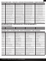
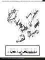
EXPLODED VIEW // EXPLOSIONSZEICHNUNG // VUE ÉCLATÉE DES PIÈCES // VISTA ESPLOSA DELLE PARTI
TLR8202
LOS43006
LOS230060 - Kicker Audio
LOS230061 - Magnaflow
LOS230056 - Clear | Transparent | Transparente | Trasparente
LOS43016
LOS43015

33
22S SCT RTR: 1:10 2WD SHORT COURSE TRUCK • INSTRUCTION MANUAL
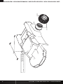
EXPLODED VIEW // EXPLOSIONSZEICHNUNG // VUE ÉCLATÉE DES PIÈCES // VISTA ESPLOSA DELLE PARTI
LOS232043
LOS232036
TLR6313
TLR5900
LOS232047
LOS232047
LOS4118
LOS235003
LOS235003
TLR6352
TLR6352
LOSA6937
LOSA6937
LOS232041
LOS232037
TLR5910
TLR5903
LOS232038
LOS232038
LOS232038
TLR5903
TLR5962
TLR5962
LOS235028
LOS232037
LOS232039
LOS232043
LOS232042
LOSA6937
LOS232042
LOSA6937
LOSA6957
LOSA6957
LOS232040
LOS232040
LOS232046
LOS232046
LOS232046
LOS232046
LOS232046
LOS232046
LOS232049
LOS232049
TLR5903
TLR5903
TLR5908
LOS231042
TLR5904
TLR5904
LOS231051
LOS231044
SPMSRX200
DYNS2200
LOS231044
LOS231044
LOS231044
LOS231044
TLR5901

34
22S SCT RTR: 1:10 2WD SHORT COURSE TRUCK • INSTRUCTION MANUAL
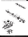
EXPLODED VIEW // EXPLOSIONSZEICHNUNG // VUE ÉCLATÉE DES PIÈCES // VISTA ESPLOSA DELLE PARTI
LOS234028
TLR6313
TLR5092
TLR235004
LOS234032
LOS234032
LOS234032
LOS234033
TLR336000
LOS232044
LOS234025
LOS232044
LOS234026
LOS234024
LOS234034
LOS234034
LOS234034
LOS234034
LOS231048
LOS234034
TLR5903
TLR5909
TLR5911
TLR5903
LOS235024
LOS234030
LOS234029
TLR5909
LOS231045
TLR5911
LOS231045
LOS231046
LOS231046
TLR5910
LOS234027
LOS234027
SPMS606
LOS231050
LOS231050
TLR336000
LOS231050
LOS231050
LOS231043
LOS231043
LOS231043
TLR5903
TLR5903
TLR5903
TLR5904
TLR6352
TLR5962
TLR5963
LOS232048
LOSA6937
LOSA6937
LOS234033
LOS231047
LOS232044
LOS231043
LOS231043
TLR8202
Front
Shock
LOS233024
LOS233021
LOS233020
LOS233021
LOS233018
LOS233023
LOS233022
LOS233022
LOS233018
LOS233023
LOS235029
LOS233022
LOS233021
LOS233019
LOS233021

35
22S SCT RTR: 1:10 2WD SHORT COURSE TRUCK • INSTRUCTION MANUAL
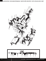
EXPLODED VIEW // EXPLOSIONSZEICHNUNG // VUE ÉCLATÉE DES PIÈCES // VISTA ESPLOSA DELLE PARTI
TLR336000
TLR5903
LOS231049
LOS231049
LOS231049
TLR5903
LOS231034
TLR6313
TLR5912
TLR5904
TLR5904
LOS235028
TLR6313
TLR5092
LOS234028
LOS235024
TLR5911
TLR8202
LOS231047
LOS234031
LOS234026
LOS234027
TLR5910
TLR5904
LOS232048
LOSA6943
LOS232045
LOS232045
LOS234024
TLR5904
LOS234029
LOS234029
LOS234032
TLR5902
VTR235178
TLR5963
TLR5962
LOS232036
LOS232045
LOS234033
LOS234032
LOSA6943
Rear
Shock
LOS233021
LOS233018
LOS233021
LOS233024
LOS233023
LOS233023
LOS235029
LOS233022
LOS233022
LOS233022
LOS233021
LOS233020
LOS233019
LOS233018
LOS233021

©2018 Horizon Hobby, LLC.
Losi, 22S, EC3, Dynamite, Prophet and the Horizon Hobby logo are trademarks or registered trademarks of Horizon Hobby, LLC. The Spektrum
trademark is used with permission of Bachmann Industries, Inc. Maxxis, Magnafl ow, Kicker, K&N, and associated logos are property of their
respective owners and are used with permission.
Created 09/18 58354 LOS03022T1/T2
WWW.LOSI.COM
-
 1
1
-
 2
2
-
 3
3
-
 4
4
-
 5
5
-
 6
6
-
 7
7
-
 8
8
-
 9
9
-
 10
10
-
 11
11
-
 12
12
-
 13
13
-
 14
14
-
 15
15


Team Losi LOS03022T2 Le manuel du propriétaire
- Catégorie
- Jouets
- Taper
- Le manuel du propriétaire
- Ce manuel convient également à
dans d''autres langues
- English: Team Losi LOS03022T2 Owner's manual
Autres documents
-
Axial AXI90074T1 Le manuel du propriétaire
-
-
-
Losi LOS03041 Le manuel du propriétaire
-
HPI Racing Maverick Strada Manuel utilisateur
-
Dynamite DYNC2030 Le manuel du propriétaire
-
Losi LOS03015 Le manuel du propriétaire
-
ECX ECX03055 Le manuel du propriétaire
-
Vaterra VTR03094 Le manuel du propriétaire
-
Team Losi Racing AXI03019 Le manuel du propriétaire