La page est en cours de chargement...

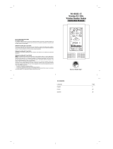
WS7034UITCA
915 MHz WIRELESS TEMPERATURE STATION
STATION DE TEMPERATURE SANS FIL 915 MHz
Instruction manual
Manuel d'lnstructions

Contents
Language Page
______________________________________________________________________
English 1
French 27

1
TABLE OF CONTENTS
Topic
Page
Inventory of contents 4
Quick Setup 5
Detailed setup guide 6
Battery Installation 6
°C/°F Temperature unit setting 11
Manual Time setting 11
Features 13
Min and Max Temperature 13
Resetting Min & Max Temperature 13
Adding additional Temperature Sensors 14
Viewing & Operating with Multiple Sensors 16
Mounting 16
Maintenance and care 22

2
Specification 22
Warranty Information 24
This product offers:
INSTANT TRAN
SMISSION
is the state
-
of
-
the
-
art
new wireless transmission technology,
exclusively designed and developed by LA
CROSSE TECHNOLOGY. INSTANT
TRANSMISSION
offers you an immediate update
(every 4 seconds!) of all your outdoor data
measured from the transmitters: follow your
climatic variations in real-time!

3
FIGURE 1
12 Hour Time
Display
Set/Channel
Button
Minimum/Maximum
& Plus Button
Sensor signal
reception icon
Indoor
Temperature
(°F or °C)
Out
door
Temperature
(°F or °C)

4
Figure 2
INVENTORY OF CONTENTS
1. Wireless Temperature Station (Figure 1)
2. Wireless Temperature Sensor (TX29U-IT) and mounting bracket. (Figure 2)
3. Instruction Manual and Warranty Card.

5
QUICK SETUP
Hint: Use good quality Alkaline Batteries; avoid rechargeable batteries.
1. Have the Wireless Temperature Station and temperature sensor 3 to 5 feet apart.
2. Batteries should be out of both units for 5 minutes.
3. Place the batteries into the Temperature sensor first and next into the Wireless Temperature
Station.
4. DO NOT PRESS ANY BUTTONS FOR 5 MINUTES.
In this time the Wireless Temperature Station and the temperature sensor will begin to communicate with
each other, and the display will show both the indoor temperature and an outdoor temperature. If the
Wireless Temperature Station does not display both temperatures after the 5 minutes, please retry the set
up as stated above. After both indoor and outdoor temperatures are displayed for 5 minutes you can
place your temperature sensor outdoors, and set your time.
The temperature sensor should be placed in a dry, shaded area (ex: under the eve of a roof). The
temperature sensor has a range of 330 feet. Any walls that the signal will have to pass through will
reduce distance. An outdoor wall or window will have up to 20 feet of resistance and an interior wall will

6
have up to 10 feet of resistance. Your distance plus resistance should not exceed 330 feet in a straight
line.
NOTE: Fog and mist will not harm your temperature sensor, but direct rain must be avoided.
DETAILED SETUP GUIDE
BATTERY INSTALLATION
- When one Temperature sensor is being used
1. First, insert the batteries to the Temperature sensor (see “Temperature sensor” below).
2. Within 2 minutes of powering up the sensor, insert the batteries to the Temperature Station (see
“Wireless Temperature station” below). Once the batteries are in place, all segments of the LCD
will light up briefly. Following the indoor temperature and the time as 12:00 will be displayed. If they
are not shown in LCD after 60 seconds, remove the batteries and wait for at least 60 seconds
before reinserting them. Once the indoor data is displayed user may proceed to the next step.
3. After the batteries are inserted, the Temperature Station will start receiving data signal from the
sensor. The outdoor temperature should then be displayed on the Temperature Station. If this
does not happen after 2 minutes, the batteries will need to be removed from both units and reset
from step 1 and the signal reception icon is no longer shown.

7
TEMPERATURE SENSOR
The Temperature sensor uses 2 x AA, IEC LR6, 1.5V batteries. To install and replace the batteries,
please follow the steps below:
1. Remove the cover at the back of the sensor.
2. Insert batteries observing the correct polarity (see marking).
3. Replace compartment cover.

8
WIRELESS TEMPERATURE STATION
The Temperature station uses 2 x AAA, IEC LR3, 1.5V batteries. To install and replace the batteries,
please follow the steps below:
1. Remove the Battery Cover on the back of the Wireless
Temperature Station.
2. Observing the correct polarity, install batteries.
3. Replace Battery Cover.
Battery
compartment
Battery cover

9
BATTERY CHANGE:
It is recommended to replace the batteries in all units regularly to ensure optimum accuracy of
these units (see Specifications below).
Please participate in the preservation of the environment. Return used batteries
to an authorised depot.
Keys:
MIN/MAX/
RESET/+ key
SET/CH key
B
Indoor Temperature in
°
F
or °C
Outdoor Temperature in
°F or °C
Time
Sensor signal
reception icon*
Transmitter
Identification No.
(Channel No.)
LCD:

10
•
••
•
*When the signal is successfully received by the Temperature Station, the icon will be switched on.
(If not successful, the icon will not be shown in LCD) So the user can easily see whether the last
reception was successful (icon on) or not (icon off). On the other hand, the short blinking of the
icon shows that a reception is currently taking place.
•
••
•
If the signal reception is not successful at the first frequency (915MHz) for 45 seconds, the
frequency will be changed to 920MHz and the learning is tried for another 45 seconds. If it is still
not successful, the reception will be tried for another 45 seconds on 910MHz. This will also be
done for re-synchronization.

11
SETTINGS
User shall press and hold the SET/ CH key for about 3 seconds to advance to the setting mode:
°C/°F TEMPERATURE UNIT SETTING
1. The digit "°F” will be flashing, user may press the MIN/MAX/ RESET/+ key to set the temp unit as
°F (degree Fahrenheit) or °C (degree Celsius).
2. Once the desired temperature unit has been chosen, confirm with the SET/CH key to advance to
the manual time setting.
flashing

12
MANUAL TIME SETTING
User shall follow the below procedures to set the time manually.
1. The hour digits start flashing in the time display section.
2. Use the MIN/MAX/ RESET/+ key to adjust the hours and then press SET/CH key to go to the
minute setting.
3. The minute will be flashing. Press the MIN/MAX/ RESET/+ key to just the minutes.
4. Confirm with the SET/CH key and exit the setting mode.
Note:
The time format is fixed to "12-hr" time display. "PM" will appear on the time LCD between the hours of
noon and midnight.
Minutes (flashing)
Hours (flashing)

13
FEATURES
MINIMUM AND MAXIMUM TEMPERATURES
1. Press and release the MIN/MAX/ RESET/+ button, “MIN” appears at the bottom of the LCD and
the recorded minimum temperatures are displayed.
2. Press and release the MIN/MAX/ RESET/+ button again to view maximum recorded temperatures.
“MAX” icon appears at the bottom of the LCD and the maximum temperatures are displayed.
3. Press and release the MIN/MAX/ RESET/+ button once more to return to the current temperatures.
RESETTING THE MINIMUM AND MAXIMUM READINGS:
User may reset the minimum and maximum temperature data to the current value by the following step:
Press and hold the MIN/MAX/ RESET/+ key for about 3 seconds to reset all the minimum/ maximum data
of all channels and the indoor sensor to the current values in a single action.

14
ADDING ADDITIONAL REMOTE SENSORS (OPTIONAL)
The WS-7034U is able to receive signals from 2 additional temperature sensors . The following are
instructions for the set-up of temperature sensor units with the WS-7034U. These extra sensors can be
purchased through the same dealer as this unit.
1. Remove all the batteries from the receiver and sensor(s) and wait 60 seconds. During these 60
seconds, press any button 20 times to discharge any excess power.
2. Insert the batteries to the first temperature sensor.
3. Within 2 minutes of powering up the first sensor, insert the batteries to the Temperature Station.
Once the batteries are in place, all segments of the LCD will light up briefly. Following the indoor
temperature and the time as 12:00 will be displayed. If they are not shown in LCD after 60
seconds, remove the batteries and wait for at least 60 seconds before reinserting them.
4. The outdoor temperature from the first sensor (channel 1) should then be displayed on the
Temperature station. If this does not happen and the signal reception icon is not shown, after 2
minutes, the batteries will need to be removed from both units and reset from step 1.
5. Insert the batteries to the second sensor as soon as the outdoor temperature readings from the
first sensor are displayed on the Temperature station.

15
NOTE: You must insert the batteries into the second sensor within 30 seconds of reception of the first
sensor.
6. The outdoor temperature from the second sensor and the "channel 2" icon should then be
displayed on the Temperature station. If this does not happen after 2 minute, the batteries will
need to be removed from all the units and reset from step 1.
7. Insert the batteries to the third sensor as soon as the "channel 2" icon and outdoor data are
displayed on the Temperature station. Then within 2 minutes, the channel 3 outdoor data from the
third sensor will be displayed and the channel icon will shift back to "1" once the third transmitter is
successfully received. If this is not happen, user shall restart the setting up from step 1.
NOTE: You must insert the batteries into the third sensor within 30 seconds of reception of the second
sensor.
IMPORTANT: Transmission problems will arise if the setting for multiple sensors is not followed as
described above. Should transmission problems occur, it is necessary to remove the batteries from all
units and start again the set-up from step 1.

16
VIEWING AND OPERATING WITH MULTIPLE REMOTE SENSOR UNITS
1. To view the temperature of a different temperature sensor unit, press the set/ch button to select to
display the outdoor temperature of the different transmitters. A shift from one channel number to
the next should be observed on the OUTDOOR LCD.
2. To view the Minimum/Maximum temperature: first select from which temperature sensor to read
data (indicated by the channel number). Pressing and releasing the MIN/MAX/ RESET/+ button
will toggle through the minimum and maximum indoor temperature, and the minimum and
maximum outdoor temperature.
MOUNTING
Note: To achieve a true temperature reading, avoid mounting in direct sunlight. We recommend that you
mount the temperature sensor on an outside North-facing wall (under the eve of a house is ideal). The
remote temperature sensor should be placed in a dry, shaded area. The remote temperature sensor has
a range of 330 feet. Keep in mind that the 330 feet is in open air with no obstructions and that radio
waves DO NOT curve around objects. Actual transmission range will vary depending on what is in the

17
path of the signal. Each obstruction (roof, walls, floors, ceilings, thick trees, etc.) will effectively cut signal
range in half.
Example: A wireless weather station receiver with a 330 feet range is mounted on an interior wall, so
that the signal has to pass through one interior wall, one exterior wall, and across the 10-foot width of the
room between the 2 walls. The first wall will reduce the range to 165 feet, and the second wall will reduce
the range to 87 feet. Factoring in the 10-foot room, this leaves a maximum of 77 feet of remaining signal
range.
This allowance is typically enough for a frame wall with non-metallic siding; however certain materials can
reduce range even further. Metal siding, stucco, and some types of glass can reduce signal range by as
much as ¾ or more, compared to the ½ reduction typical of most obstructions. It is possible to receive a
signal through these materials,
however maximum range will be much less due to their tendency to
absorb or reflect a much larger portion of the sensor’s signal
.

18
WIRELESS TEMPERATURE STATION
The Wireless Temperature Station comes with the table stand attached to the back of
the Receiver. If you wish to use the table-stand, simply place the Wireless
Temperature Station in an appropriate location, and pull out on the attached stand.
1/57