ROBBE RB 15/4 Kit Operating Instructions Manual
- Catégorie
- Jouets télécommandés
- Taper
- Operating Instructions Manual
La page est en cours de chargement...
La page est en cours de chargement...

Betriebsanleitung, Operating instructions instructions, Notice d’utilisation
RB 15/4 Kit
3
Technische Daten
Länge: ca. 400 mm
Breite: ca. 245 mm
Radstand: ca. 265 mm
Gewicht: ca. 1750 g
Erforderliches Zubehör für den Betrieb Bestell. Nr.
Fernsteuersender Megatech T-2PHKA F2223 oder
Fernsteuersender Megatech T-2PL F2206
(Lenk- und Gas-/Bremsservo im Lieferumfang der
Fernsteueranlagen)
NC-Zelle 1,2V RSZ, 12x 8004
(8x Sender, 4x Empfänger)
Ladegerät Lader 5r 8308
Senderladekabel F1415
Ladekabel BEC F1418 oder
Empfängerladekabel F1416
Glühkerze Enya No.4 (VE10) 71270010
Glühkerzenstecker mit Ladegerät 6085
Empfohlenes Zubehör und Werkzeug
Sekundenkleber 5063
Präzisionsfett 5532
Schraubensicherungslack „Loctite“ 5074
Luftfilteröl
70081000
Tankflasche 7565
Roktan S 10 Kraftstoff 5315
Polycarbonatfarben nach Wahl
Kleine Spitzzange ---
Kreuzschlitzschraubendreher ---
Inbusschlussel SW 1,5 ---
Kerzenschlüssel 6095
Ersatz- und Tuningteile
Eine Gesamtübersicht der Ersatzteile, der Motor-
Ersatzteile und der Tuningteile finden Sie auf den Seiten
23 bis 31.
Bau- und Betriebsanleitung
Hinweise: Zur Vermeidung von Verletzungen ist besonde-
re Vorsicht im Umgang mit den erforderlichen
Werkzeugen und Bauteilen des Modells geboten.
Es empfiehlt sich, die Anleitungen aufzuheben, um bei
Reparaturen und Ersatzteilbestellungen nachschlagen zu
können.
Specification
Length: approx. 400 mm
Width: approx. 245 mm
Wheelbase: approx. 265 mm
Weight: approx. 1750 g
Recommended accessories: Order No.
Megatech T-2PHKA RC transmitter F2223 or
Megatech T-2PL RC transmitter F2206
(steering and throttle / brake servos supplied with RC set)
NC cell, 1.2 V RSZ, 12 x 8004
(8 x transmitter, 4 x receiver)
Battery charger, Lader 5r 8308
Transmitter charge lead F1415
BEC charge lead F1418 or
Receiver battery charge lead F1416
Glowplug, Enya No. 4 71270010
(pack of 10)
Glow clip with charger 6085
Recommended accessories and tools
Cyano-acrylate glue 5063
Precision grease 5532
“Loctite“ thread lock fluid 5074
Air filter oil
70081000
Tank filler bottle 7565
Roktan S 10 glow fuel 5315
Polycarbonate paints To choice
Small pointed-nose pliers ---
Cross-point screwdriver ---
Allen key, size 1.5 ---
Glowplug spanner 6095
Replacement parts, upgrade parts
Pages 23 - 31 show overall views of replacement parts for
the model and motor and upgrade parts.
Building and operating instructions
Note: tools and some of the model’s components are
potentially dangerous; please take great care when hand-
ling them to avoid injury.
We recommend that you keep the instructions in a safe
place so that you can refer back to them for repairs and
when ordering spare parts.
Caractéristiques techniques
longueur : approx. 400 mm
largeur : approx. 245 mm
empattement : approx. 265 mm
poids: approx. 1750 g
Accessoires recommandés réf.
radiocommande Megatech T-2PHKA F2223 ou
radiocommande Megatech T-2PL F2206
(servo de direction, des gaz et du frein
avec les ensembles de radiocommande)
éléments Cd-Ni 1,2V RSZ, 12x 8004
(8x émetteur, 4x récepteur)
chargeur Lader 5r 8308
cordon de charge de l’émetteur F1415
cordon de charge BEC F1418 ou
cordon de charge pour accu récepteur F1416
bougie Enya réf. 4, (10pcs) 71270010
soquet à bougie avec chargeur 6085
Accessoires recommandés et outillage
colle cyanoacrylate 5063
graisse de précision 5532
vernis de freinage “Loctite“ 5074
huile de filtr
e à air 70081000
flacon de remplissage du réservoir 7565
carburant Roktan S 10 5315
peintures à base polycarbonate au choix
petite pince pointue ---
tournevis à tête croisée ---
clé mâle pour vis six pans creux, taille 1,5 ---
clé à bougie 6095
Pièces de rechange et de compétition
Vous trouverez une vue d’ensemble des pièces de
rechange, des pièces de rechange destinés au moteur et
des pièces de compétition sur les pages 23 à 31.
Notice d’assemblage et d’utilisation
À noter : pour éviter de se blesser, il est recommandé de
manipuler les outils indispensables et les composants du
modèle avec beaucoup de précaution.
Nous recommandons de conserver la notice du modèle
afin de pouvoir s’y reporter pour les réparations éventuel-
les et la commande ultérieure de pièces de rechange.
No.
2028
La page est en cours de chargement...

Betriebsanleitung, Operating instructions instructions, Notice d’utilisation
RB 15/4 Kit
5
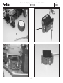
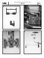
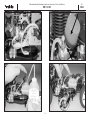
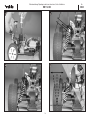
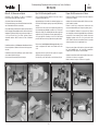
Bild 1, Vorbereiten des Chassis
- Die Räder auf die Sechskantmitnehmer aufstecken und
mit den M 4-Radmuttern festsetzen.
- Luftfilter aufsetzen, um ein Eindringen von Schmutz in
den Motor zu verhindern.
- Glühkerze mit dem beigefügten Dichtring versehen und
in den Zylinderkopf eindrehen.
Bild 2, Vorbereiten des Lenkservos
- Servohebelschraube lösen, Steuerscheibe bzw.
Kreuzhebel abnehmen.
- Servo mit Gummitüllen bzw. Unterlagen versehen.
- Den vorderen Servohalter am Lenkservo verschrauben.
Bild 3, Einbau des Lenkservos
- Servo einsetzen. Vorderen Servohalter mit der
Senkschraube am Chassis montieren. Servo am hinte-
ren Halter mit einer Blechschraube befestigen.
Bild 4, Vorbereiten des Drosselservos
- Servohebelschraube lösen, Steuerscheibe bzw.
Kreuzhebel abnehmen.
- Servo mit Gummitüllen bzw. Unterlagen versehen.
Fig. 1, preparing the chassis
- Fit the wheels on the hexagon drivers and secure them
with the M4 wheel nuts.
- Fit the air filter to prevent dirt and dust entering the
motor.
- Fit the sealing ring on the glowplug and screw it into the
cylinder head.
Fig. 2, preparing the steering servo
- Undo the servo output screw and lift off the output disc
or lever.
- Press the rubber grommets into the mounting lugs of
the servo.
- Screw the front servo mount to the steering servo.
Fig. 3, installing the steering servo
- Install the steering servo. Fix the front servo mount to
the chassis using the countersunk screw. Attach the
servo to the rear mount using a self-tapping screw.
Fig. 4, preparing the throttle servo
- Undo the servo output screw and lift off the output disc
or lever.
- Press the rubber grommets into the mounting lugs of
the servo.
Fig. 1, préparatifs sur le châssis
- Installer les roues sur l'entraîneur six pans et les fixer
avec l'écrou de roue M4.
- Mettre le filtre à air en place afin d’éviter d’introduction
d’impuretés dans le moteur.
- Munir la bougie du joint d’étanchéité joint et l’engager
dans la tête du cylindre.
Fig. 2, préparatifs sur le servo de direction
- Desserrer la vis de palonnier du servo et retirer le palon-
nier circulaire ou le palonnier en croix.
- Munir le servo des passe-fils ou des support.
- Visser le support-servo avant au servo de direction.
Fig. 3, mise en place du servo de direction
- Mettre le servo en place. Monter le support-servo avant
sur le châssis à l’aide des six vis. Fixer le servo au sup-
port-servo arrière à l’aide d’une vis autotaraudeuse.
Fig. 4, préparatifs sur le servo des gaz
- Desserrer la vis de palonnier du servo et retirer le palon-
nier circulaire ou le palonnier en croix.
- Munir le servo des passe-fils ou des support.
No.
2028

5
6
7
8
6
Betriebsanleitung, Operating instructions instructions, Notice d’utilisation
RB 15/4 Kit
No.
2028

Betriebsanleitung, Operating instructions instructions, Notice d’utilisation
RB 15/4 Kit
7
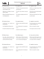
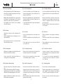
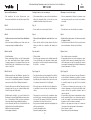
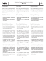
Bild 5, Einbau des Gasservos
- Das Gasservo in den Ausschnitt neben der RC-Box ein-
setzen und mit 4 Blechschrauben befestigen.
Bild 6, der Schalter
- Die Splinte herausziehen, den Deckel der RC-Box
abnehmen. Den Schalter im Schlitz des Deckels ein-
bauen.
Bilder 7 und 8, Empfänger und Akku (box)
- Servokabel und Schalter am Empfänger anschließen.
- Batterien / Akkus einsetzen, Polung beachten.
- Akkubox am Schalterkabel anschließen.
Fig. 5, installing the throttle servo
- Place the throttle servo in the opening next to the RC
box and secure it with four self-tapping screws.
Fig. 6, the switch
- Withdraw the split pins and lift off the lid of the RC box.
Install the switch in the rectangular hole in the cover.
Figs. 7 and 8, receiver and batterie (box)
- Connect the servo lead and switch to the receiver.
- Install the dry or rechargeable cells, taking care to main-
tain correct polarity.
- Connect the battery box to the switch harness.
Fig. 5, mise en place du servo des gaz
- Installer le servo des gaz dans le compartiment à côté
du boîtier de l’ensemble de réception et le fixer avec
quatre vis autotaraudeuses.
Fig. 6, l’interrupteur
- Extraire la goupille, retirer le couvercle du boîtier de
l’ensemble de réception. Monter l’interrupteur dans la
fente du couvercle.
Figures 7 et 8, récepteur et porte-accu
- Raccorder les cordons des servos et l’interrupteur au
récepteur.
- Mettre les piles/les accus en place en tenant compte
des polarités indiquées.
- Raccorder le porte-accu au cordon-interrupteur.
No.
2028
La page est en cours de chargement...

9
No.
2028
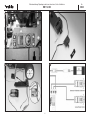
Bild 9, Empfängereinbau
- Empfänger einlegen, Akkubox einsetzen.
- Die Servokabel durch den Schlitz der RC-Box nach
innen führen.
- Kabel sauber verlegen, nicht knicken oder einklemmen.
Wichtig: Die Kabel müssen so verlegt werden, daß sie
nicht mit Zahnrad oder Bremsscheibe in Berührung
kommen können.
- Die Litzenantenne des Empfängers durch die Bohrung
des Deckels nach außen führen.
Bilder 10 und 11, die Empfängerantenne
- Deckel wieder verschließen.
- Die Litzenantenne des Empfängers in das
Antennenröhrchen einfädeln.
- Das Antennenröhrchen in den Antennenfuß einsetzen.
Bild 12
- Zuerst den Sender einschalten.
- Die Empfangsanlage durch Betätigen des Schalters
einschalten.
- Beide Servos mit der Fernsteuerung in Neutralstellung
bringen.
- Ausschalten in umgekehrter Reihenfolge.
Fig. 9, installing the receiver and the battery box
- Install the receiver and the battery box
- Run the servo leads into the RC box through the slots
provided.
- Deploy the cables neatly; don’t kink them or allow them
to become snagged.
Important: it is essential to arrange the cables in such
a way that there is no chance of them coming into
contact with the gears or brake disc.
- Locate the flexible wire aerial attached to the receiver
and thread it out through the hole in the lid.
Figs. 10 and 11, the aerial
- Close the cover again.
- Slip the wire aerial attached to the receiver into the aeri-
al sleeve.
- Push the aerial sleeve into the aerial base.
Fig. 12
- Switch the transmitter on first.
- Turn on the receiving system by operating the switch.
- Set both servos to neutral (centre) from the transmitter
- Switch off in the reverse order, i.e. receiver first.
Fig. 9, mise en place du récepteur et du porte-accu
- Mettre le récepteur et le boîtier de l’accu en place.
- Passer les cordons de servo dans la fente du boîtier de
l’ensemble de réception.
- Disposer proprement le cordon sans le plier ni le coin-
cer.
Important : les cordons doivent être agencés de
manière qu’ils ne puissent entrer en contact avec la
roue dentée ou le disque de frein.
- Amener l’antenne souple du récepteur vers l’extérieur
en la passant par l’alésage du boîtier.
Figures 10 et 11, l’antenne du récepteur
- Refermer le couvercle.
- Enfiler l’antenne souple du récepteur dans le tube
d’antenne.
- Planter le tube d’antenne dans le pied d’antenne.
Fig. 12
- Mettre d’abord l’émetteur en marche.
- Mettre l’ensemble de réception en marche en
actionnant l’interrupteur.
- Amener les deux servos en position neutre à l’aide de
l’ensemble de radiocommande.
- En fin de séance de pilotage, procéder dans l’ordre
inverse de la mise en marche.
Betriebsanleitung, Operating instructions instructions, Notice d’utilisation
RB 15/4 Kit
La page est en cours de chargement...

11
No.
2028
Bild 13, das Lenkgestänge
- Die zwei Kugelgelenke auf die M 3 Gewindestange auf-
drehen. Das so gefertigte Lenkgestänge auf eine Länge
von ca. 50 mm einstellen.
- Hinweis: Dem Montagekasten liegen Servohebel mit
verschiedenen Feinverzahnungen bei. Die Hebel für
Futaba Servos sind mit einem “F” gekennzeichnet.
- Den Kugelkopf für die Lenkung in den einarmigen
Servohebel eindrehen.
Bild 14, Lenkung
- Vorbereiteten Servohebel auf das Lenkgestänge auf-
drücken.
- Zweites Kugelgelenk auf den Kugelkopf des Servo-
Savers aufdrücken.
- Hebel senkrecht auf das Servo stecken und mit der
Servohebelschraube sichern.
Bild 15, Lenkung prüfen
- Bei Drehen des Lenkrads nach rechts (links) müssen die
Räder nach rechts (links) einschlagen.
- Ist dies nicht der Fall, Servo-Reverse-Schalter des
Senders (Kanal 1, Lenkung) betätigen.
Bild 16, das Gas / Bremsgestänge
- Den kurzen Arm des Gas- / Bremshebels wegschnei-
den.
- Das Gas- /Bremsgestänge gemäß Bild 16 anfertigen.
Zwei Bohrungen im Servohebel auf 2 mm aufbohren.
Die Mutter der Gestängekupplung mit Loctite sichern.
Hinweis: Der Rändel für die Bremse wird erst nach
Einbau der Gestänge aufgedreht.
Fig. 13, the steering pushrod
- Screw the two ball-links onto the M3 threaded rod to
form the steering pushrod. Set the overall length of the
pushrod to about 50 mm.
- Note: the kit is supplied with servo output arms with dif-
ferent spline patterns. The arms for Futaba servos are
marked with a letter “F”.
- Screw the ball-end bolt into the single-sided output arm
on the steering servo.
Fig. 14, steering
- Press the steering pushrod onto the prepared servo
output arm.
- Press the second ball-link onto the ball-end bolt on the
servo saver.
- Fit the output arm on the servo and secure it with the
servo output screw.
Fig. 15, checking the steering
- When you turn the steering wheel to the right (left) the
front wheels must also turn to the right (left).
- If this is not the case, operate the servo reverse switch
of the transmitter (channel 1, steering).
Fig. 8, throttle / brake pushrod
- Cut away the short arm from the throttle / brake lever.
- Assemble the throttle / brake pushrod as shown in Fig.
16. Drill 2 holes in the lever to 2 mm Ø. Secure the nut
of the pushrod connector with a drop of Loctite (thread-
lock fluid).
- Note: the knurled nut for the brake is not fitted until the
pushrod has been installed.
Fig. 13, la tringle de direction
- Visser les deux biellettes sur la tige filetée M 3. Régler
la tringle de direction sur une longueur de 50 mm envi-
ron.
- À noter : dans la boîte de construction se trouvent des
palonniers de servo présentant des dentures fines dif-
férentes. Les palonniers destinés aux servos Futaba
portent le repère “F.
- Engager la biellette de direction dans le palonnier de
servo à un bras.
Fig. 14, direction
- Planter le palonnier de servo préparé sur la tringle de
direction.
- Planter une seconde biellette sur le pivot sphérique du
sauve-servo.
- Planter le palonnier sur le servo et le fixer avec la vis de
palonnier de servo.
Fig. 15, contrôle de la direction
- Lorsque vous tournez le volant vers la droite (vers la
gauche) il faut que les roues se déplacent vers la droite
(vers la gauche).
- Si ce n’est pas le cas, actionner le commutateur d’in-
version de la course du servo (Reverse) de l’émetteur
(voie 1, direction).
Fig. 8, la tringle gaz/frein
- Couper le bras court du palonnier gaz/frein.
- Réaliser la tringle gaz/frein selon les indications de la
fig. 16. Agrandir 2 trous du palonnier (2 mm). Bloquer
l’écrou de l’accouplement de tringle avec du Loctite.
À noter : ne desserrer la molette de frein qu’après la
mise en place.
Betriebsanleitung, Operating instructions instructions, Notice d’utilisation
RB 15/4 Kit
La page est en cours de chargement...

13
No.
2028
Betriebsanleitung, Operating instructions instructions, Notice d’utilisation
RB 15/4 Kit
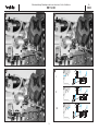
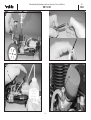
Bild 17, Vergaser und Bremse
- Z-Kröpfung des Gasgestänges im Drosselhebel des
Vergasers einhängen (obere Bohrung).
- Bremsgestänge durch den Bremshebel fädeln.
Silikonschlauchstück aufschieben, Rändelmutter auf-
drehen.
- Servohebel nach Abb. 20, II auf das Gasservo aufset-
zen und mit der Servohebelschraube sichern.
- Den Luftfilter abnehmen, um die Stellung des
Drosselkükens im Vergaser prüfen zu können.
- Gas - Bremshebel am Sender ziehen.
(“Vollgasstellung”). Das Drosselküken im Vergaser
muß ganz öffnen und die Bremse darf nicht greifen.
- Wenn das Drosselküken geschlossen bleibt und die
Bremse greift, Servo-Reverse Schalter Drossel am
Sender betätigen.
Bild 18
- In Leerlaufstellung (Mittelstellung) ist der Vergaser bis
auf einen schmalen Spalt (ca. 0,5 mm) komplett
geschlossen und die Bremse greift nicht!
- Stellringe auf dem Gasgestänge, falls erforderlich, ent-
sprechend verschieben.
Bild 19
- Den Gas/Bremshebel am Sender ganz nach vorn in
Stellung „Bremsen“ bewegen. Die Feder auf dem
Gasgestänge wird dabei zusammengedrückt. Das
Drosselküken im Vergaser darf nur so weit schließen,
daß noch eine schmale Öffnung zu erkennen ist (ca. 0,5
mm). Gleichzeitig muss der Bremshebel und der daran
befestigte Bremsexcenter die Backen der Bremse so
weit betätigen, daß die Bremse voll greift. Die richtige
Bremskraft kann erst im Fahrversuch ermittelt werden.
Bild 20
-
Die Stellungen von Dr
osselküken und Br
emse
- Bild I: Vollgas, Bremse gelöst
-
Bild II:
Leerlauf, Br
emse gelöst
- Bild III: Leerlauf, Bremse greift
Fig. 17, carburettor and brake
- Connect the pre-formed end of the throttle pushrod to
the throttle arm on the carburettor (upper hole).
- Slip the brake pushrod through the brake lever, fit the
piece of silicone hose, then screw the knurled nut in
place.
- Press the output arm onto the throttle servo and secu-
re it with the servo output screw - see fig. 20, II.
- Remove the air filter so that you can check the position
of the throttle barrel in the carburettor.
- Push the throttle / brake lever into the transmitter case
(„full-throttle position“). The throttle barrel in the carbu-
rettor should now open fully, and the brake should not
engage.
- If the throttle barrel remains closed and the brake enga-
ges, operate the servo reverse switch of the transmitter.
Fig. 18
- At the idle position (centre) the carburettor should be
completely closed apart from a narrow slit (approx. 0.5
mm), and the brake should not engage.
- If necessary adjust the position of the collets on the
throttle pushrod until this is the case.
Fig. 19
- Move the throttle/brake lever of the transmitter fully for-
ward to the „Brake“ position. This action compresses
the spring on the throttle pushrod. The throttle barrel in
the carburettor should now close to the point where
only a narrow slit is visible (approx. 0.5 mm). At the
same time the brake lever and the brake eccentric atta-
ched to it should move the brake shoes until the brake
engages fully. The correct braking force can only be
found during trial-runs.
Fig. 20
-
Thr
ottle barr
el and brake positions
- Fig. I: Full throttle, brake disengaged
-
Fig. II:
Idle, brake disengaged
- Fig. III: Idle, brake engaged
Fig. 17, Carburateur et frein
- Accrocher l’extrémité en Z de la tringle des gaz dans le
premier trou du palonnier du carburateur.
- Enfiler la tringle de frein dans le palonnier de frein.
Enfiler le morceau de flexible en silicone, desserrer
l’écrou moleté.
- Mettre le palonnier de servo en place sur le servo des
gaz et le fixer avec la vis du palonnier, c.f. fig. 20, II.
- La tringle des gaz et du frein est préréglée à l’usine.
- Retirer le filtre à air pour pouvoir contrôler la position du
boisseau dans le carburateur.
- Lorsque vous poussez le manche des gaz/frein dans le
boîtier de l’émetteur (”position plein gaz”), le boisseau
dans le carburateur doit être entièrement ouvert et le
frein ne doit pas mordre.
- Si le boisseau reste fermé et que le frein mord,
actionner le commutateur d’inversion de la course du
servo de l’émetteur.
Fig. 18
- En position ralenti (position médiane) le carburateur est
pratiquement fermé, il ne subsiste qu’une petite ouver-
ture (approximativement 0,5 mm) et le frein ne mord
pas! Si nécessaire, décaler las bagues d’arrêt en
conséquence sur la tringle des gaz.
Fig. 19
- Amener le manche gaz/frein de l’émetteur complète-
ment vers l’avant en position “freinage”. Le ressort sur
la tringle est alors complètement comprimé. Le bois-
seau doit pratiquement être fermé dans le carburateur,
il ne doit subsister qu’une petite fente (approximative-
ment 0,5 mm). Simultanément, le palonnier de frein et
l’excentrique solidaire doivent actionner les mâchoires
du frein de manière que le frein agisse. L’effort de frei-
nage sera déterminé après les premiers essais du
modèle.
Fig. 20
- Les positions du boisseau et du frein
- Fig. I: plein gaz, frein desserré
-
Fig. II:
ralenti, fr
ein desserré
- Fig. III: ralenti, le frein mord
La page est en cours de chargement...

15
No.
2028
Betriebsanleitung, Operating instructions instructions, Notice d’utilisation
RB 15/4 Kit
Starten und Einlaufhinweise
- Wir empfehlen, die ersten Fahrversuche ohne
Karosserie durchzuführen, bis der Motor eingestellt ist.
Bild 21
- Korrekter Anschluß der Kraftstoffschläuche
Bild 22
- Luftfilter aufsetzen und mit dem kleinen Kabelbinder
sichern.
- Auf festen Sitz des Luftfilters achten. Staub, der in den
Vergaser gelangt, beschädigt den Motor.
Bilder 23 und 24
- Modell auftanken.
- Durch mehrmaliges Drücken auf die Pumpmechanik
des Tanks wird Kraftstoff zum Vergaser gefördert.
Solange pumpen bis Sie erkennen können, dass der
Kraftstoff durch die Schlauchleitung in den Vergaser
eintritt - siehe Pfeil.
Bild 25, Seite 16
- Glühkerzenstecker auf die Glühkerze aufsetzen. Den
Motor mit dem Seilzugstarter anlassen. Der Gashebel
muss sich in Leerlaufstellung befinden. Seilzugstarter
immer nur zu etwa 2/3 der Seillänge herausziehen.
- Wenn der Motor nach vier bis fünf Startversuchen nicht
anspringt oder sich nur sehr schwer betätigen lässt,
führen Sie folgende Schritte durch:
- Möglicherweise befindet sich zuviel Kraftstoff im
Brennraum. In diesem Fall die Glühkerze herausschrau-
ben (Steckschlüssel SW8) und durch mehrfaches
Starten den überschüssigen Kraftstof
f ausblasen.
- Achten Sie darauf, daß Sie sich nicht mit Gesicht oder
Händen über der Kerzenöffnung befinden.
-
Glühkerze wieder einschrauben.
- Startvorgang wiederholen.
Starting the motor, notes on running-in
- We recommend that you carry out the first few trial runs
without the bodywork fitted; at least until you have
established the final settings for the motor.
Fig. 21
- Correct method of connecting the fuel lines
Fig. 22
- Fit the air filter and tighten the small cable tie to secu-
re it.
- Ensure that the air filter is firmly attached. Any dust
which gets inside the carburettor will damage the
motor.
Figs. 23 and 24
- Fill the fueltank.
- Press the pump mechanism on the fueltank repeatedly
to force fuel through to the carburettor. Continue pum-
ping until you see fuel entering the carburettor through
the fuel line - see arrow.
Fig. 24, page 16
- Push the glow driver onto the glowplug. Check that the
throttle lever is at the idle position, then start the motor
by pulling the pull-cord starter. Never pull out the star-
ter cord more than about 2/3 of its full length.
- If the motor does not start after four or five attempts, or
is very difficult to turn over, carry out the following pro-
cedure:
- There may be too much fuel in the combustion cham-
ber. Check this by unscrewing the glowplug complete-
ly (8 mm A/F box spanner) and pull the starter cord
several times to blow out the excess fuel.
- Keep your face and hands away from the glowplug hole
while you are doing this.
-
Scr
ew the glowplug in place.
- Repeat the starting procedure.
Démarrage et conseils de rodage
- Nous recommandons d’effectuer les premiers essais
sans carrosserie jusqu’à ce que le moteur soit parfaite-
ment réglé.
Fig. 21
- Raccordement correct des flexibles de carburant
Fig. 22
- Mettre le filtre à air en place et le fixer avec une peti-
te ligature de câble.
- Contrôler l’assise du filtre à air. Si de la poussière entre
dans le carburateur, elle risque de le détériorer.
Figures 3 et 24
- Faire le plein du réservoir du modèle.
- En appuyant plusieurs fois sur la mécanique de pom-
page du réservoir, amener le carburant jusqu’au réser-
voir. Pomper jusqu’à ce qu’il soit possible de constater
le passage du carburant dans le flexible d’alimentation
jusqu’au carburateur - Cf. flèche.
Fig. 25, page 16
- Installer le soquet à bougie sur la bougie. Démarrer le
moteur à l’aide du démarreur à cordelette. Le manche
des gaz doit se trouver au ralenti. Ne tirer le démarreur
à cordelette chaque fois que des 2/3 de la cordelette
environ.
- Si le moteur ne démarre pas après quatre ou cinq
essais de démarrage, ou si le moteur est difficile à faire
tourner, effectuer les opérations suivantes dans la
séquence décrite :
- il est possible qu’il y ait trop de carburant dans la cham-
bre de combustion. Dans ce cas, dévisser la bougie (clé
à tube de 8 surplat) et en actionnant plusieurs fois le
démarreur, éjecter l’excédent de carburant.
- Veiller à ne pas approcher le visage ou les mains de
l’ouvertur
e de la bougie pendant cette manœuvr
e.
- Visser la bougie en place.
- Reprendre la procédure de démarrage.

Betriebsanleitung, Operating instructions instructions, Notice d’utilisation
RB 15/4 Kit
16
No.
2028
27
28
26
25
L
HD

17
No.
2028
Betriebsanleitung, Operating instructions instructions, Notice d’utilisation
RB 15/4 Kit
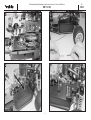
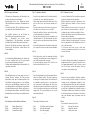
Bild 26
- Springt der Motor noch nicht an: Glühkerze heraus-
schrauben. Stecker auf Glühkerze aufsetzen, die
Wendel muss rotglühend werden - siehe Pfeil. Wenn die
Kerze nur schwach glüht, Akku laden. Glüht die Kerze
nicht, diese ersetzen. Glühkerze einschrauben.
- Startvorgang wiederholen.
Bild 27
- Der Motor muss nun mit geringer Drehzahl im Leerlauf
durchlaufen. Wenn der Leerlauf zu hoch ist, die
Leerlauf-Anschlagschraube „L“ gegen den
Uhrzeigersinn in kleinen Schritten herausdrehen.
- Wenn der Motor stehen bleibt, ist der Leerlauf zu nied-
rig. In diesem Fall die Leerlauf-Anschlagschraube „L“
im Uhrzeigersinn hineindrehen.
Bild 28
- Der Leerlauf sollte nach dem Einlaufen immer so tief
wie möglich einreguliert sein, ohne dass der Motor ste-
hen bleibt.
- Der Motor muss mit einem „fetten Gemisch einlaufen,
d.h. bei mäßiger Drehzahl und deutlicher
Rauchentwicklung aus dem Schalldämpfer.
- „Fettes“ Gemisch wird durch schrittweises
Herausdrehen der Hauptdüsennadel „HD“ erreicht.
- Ein neuer Motor muss erst mit ca. 5 Tankfüllungen ein-
laufen, bevor er seine volle Leistung abgeben kann.
Zwischen den Einlaufperioden den Motor immer gut
abkühlen lassen.
- Um den Motor sofort zu belasten, auf einem ebenen
Untergrund die ersten Runden drehen.
- Nach dem Einlaufen die Leistung dadurch steigern,
dass die Hauptdüsennadel schrittweise im
Uhrzeigersinn hineingedreht wird.
- Die Hauptdüsennadel ist richtig eingestellt, wenn der
Motor seine höchste Drehzahl erreicht, ohne stehen zu
bleiben. Wenn der Motor stoppt und sehr heiß wird
(Gemisch zu „mager“), die Hauptdüsennadel ein wenig
herausdrehen.
- Zum Abstellen des Motors den Gasknüppel in
Leerlaufstellung bringen und den Schalldämpferauslaß
kurz verschließen (Lappen).
Fig. 26
- If the motor still does not start: unscrew the glowplug
and push it into the glow driver. The filament should
now glow bright red - see arrow. If the plug only glows
weakly, recharge the glow driver battery. If the filament
does not glow at all, replace the plug. Re-install the glo-
wplug.
- Repeat the starting procedure.
Fig. 27
- The motor should now run steadily at a low (idle) speed.
If the idle speed is too high, unscrew the idle stop screw
„L“ (anti-clockwise) in very small increments.
- If the motor stops, the idle speed is too low. In this case
screw in the idle stop screw „L“ (clockwise) slightly.
Fig. 28
- The idle speed should be set as low as possible with-
out any tendency for the motor to cut (stop), but final
adjustment is only possible once the motor is properly
run-in.
- The motor must be run-in using a „rich“ mixture, i.e. at
moderate speed and with a distinctly smoky exhaust
plume from the silencer.
- A „rich“ mixture is achieved by unscrewing the main
needle valve „HD“ in small increments.
- The new motor has to be run-in for about five comple-
te tankfuls of fuel before it is capable of producing full
power. Allow the motor to cool down thoroughly bet-
ween runs.
- The motor should be given a light „load“ even when
running-in, so place the model on an even surface and
drive it around gently.
- Once the motor is run-in you can increase its power by
screwing in the main needle valve (clockwise) in small
increments.
- The main needle is correctly set when the motor rea-
ches maximum speed without any tendency to cut. If
the motor stops and is obviously very hot, the mixtur
e
is too „lean“: unscrew the main needle slightly.
- To stop the motor: move the throttle stick to the idle
position and hold a rag over the silencer outlet briefly
.
Fig. 26
- Si le moteur ne démarre pas : dévisser la bougie. Installer
le soquet sur la bougie, le filament de la bougie doit deve-
nir incandescent - Cf. flèche. Si l’incandescence du fila-
ment est trop faible, charger l’accu. Si le filament ne rougit
pas du tout, remplacer la bougie. Remettre la bougie en
place.
- Reprendre la procédure de démarrage.
Fig. 27
- Le moteur doit tourner maintenant sans faillir à faible régi-
me. Si le régime du ralenti est trop élevé, dévisser la vis de
butée du ralenti “L” dans le sens contraire des aiguilles
d’une montre, en procédant par petites étapes.
- Lorsque le moteur cale, le régime du ralenti est insuffisant.
Dans ce cas, il faut serrer la vis de butée du ralenti “L” dans
le sens des aiguilles d’une montre.
Fig. 28
- Un fois le moteur rodé, il faut que le régime du ralenti soit
toujours réglé le plus bas possible sans toutefois que le
moteur cale.
- Le moteur doit tourner au cours du rodage avec un “mélan-
ge gras, c’est-à-dire qu’à bas régime, les gaz d’échappe-
ment doivent être importants (fumée) au niveau du silen-
cieux.
- Le mélange “gras” est obtenu en desserrant par étapes, le
pointeau du gicleur principal “HD”.
- Roder d’abord un moteur neuf avec approximativement 5
pleins du réservoir, ce n’est qu’après cela que le moteur
sera en mesure de fournir toute sa puissance. Entre les dif-
férents pleins de rodage, laisser systématiquement refroidir
complètement le moteur.
- Pour charger immédiatement le moteur, effectuer les pre-
mières rondes avec le modèle sur une piste parfaitement
plane.
- Après le rodage, augmenter la puissance du moteur en ser-
rant progressivement le pointeau du gicleur principal dans
le sens des aiguilles d’une montre.
- Le pointeau du gicleur principal est parfaitement réglé lor-
sque le moteur atteint des régimes élevés sans caler.
Lorsque le moteur cale ou devient très chaud (le mélange
est trop maigre), desserrer légèrement le pointeau du
gicleur principal. Pour couper le moteur
, amener le manche
des gaz au ralenti et boucher brièvement la sortie du pot
d’échappement (avec un chiffon par exemple).
La page est en cours de chargement...

19
No.
2028
Betriebsanleitung, Operating instructions instructions, Notice d’utilisation
RB 15/4 Kit
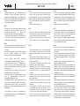
Fahrwerkseinstellungen:
Hinweis:
Das Chassis ist werksseitig grundeingestellt.
Wenn Sie sich mit den Fahreigenschaften vertraut
gemacht haben, können Sie das Modell durch
Veränderungen an den Fahrwerkseinstellungen auf Ihre
Bedürfnisse abstimmen.
Bild 29, Einstellen der Bremskraft:
- Rechtsdrehen der Rändelmutter – Fahrzeug bremst
früher und stärker.
- Linksdrehen der Rändelmutter – Fahrzeug bremst spä-
ter und schwächer.
Bilder 30 und 31, Einstellen der Stoßdämpfer:
- Beachten Sie, daß alle folgenden Einstellungen an bei-
den Seiten einer Achse durchgeführt werden müssen,
um den beschriebenen Effekt zu erzielen.
- Durch Verwendung von Ringen verschiedener Höhe auf
dem Stoßdämpferzylinder verändern Sie die
Bodenfreiheit des Modells, nicht die Federhärte. Die
Einstellung der Bodenfreiheit richtet sich nach der
Beschaffenheit des befahrenen Untergrundes und soll-
te immer möglichst gering gehalten werden, ohne daß
das Chassis beim Durchfedern den Boden berührt.
- Die Federhärte können Sie durch den Austausch der
serienmäßigen Federn gegen die Tuningfedern
No.20170084 (Ø 1,3mm) oder No.20170085 (Ø 1,4mm)
verändern.
- Am Einfachsten lässt sich die Federcharakteristik durch
einen geänderten Befestigungswinkel der
Stossdämpfer erreichen. Im Lieferzustand sind die
Stossdämpfer des Modells so montiert, das sich die
Fahreigenschaften für einen relativ unebenen
Untergrund eignen. Man spricht von einem weichen
Dämpfungsverhalten.
- Montiert man die Stossdämpfer steiler, wird das
Dämpfungsverhalten härter und eignet sich besonders
für glatte und ebene Pisten.
Chassis adjustments:
Note:
the chassis is factory-adjusted to suit normal ope-
rating conditions. Once you have become familiar with its
running characteristics and handling you may wish to
make adjustments to the chassis settings to suit your dri-
ving style.
Fig. 29, adjusting braking power:
- Turn the knurled nut to the right: the car brakes earlier
and more strongly.
- Turn the knurled nut to the left: the car brakes later and
less strongly.
Figs. 30 and 31, adjusting the shock absorbers:
- Note that all the following adjustments must be carried
out at both sides (ends) of the same axle in order to
achieve the effect described.
- Rings of different height can be fitted to the shock
absorber cylinders. This alters the model's ground clea-
rance - not the hardness of the suspension. Ground
clearance only needs to be adjusted to suit the surface
quality of the track you are using. It should always be
set to the lowest possible clearance at which the chas-
sis does not quite touch the ground at maximum sus-
pension travel.
- The stiffness of the suspension can be altered by remo-
ving the standard springs and fitting the upgrade
springs No. 20170084 (1.3 mm Ø) or No. 20170085 (1.4
mm Ø).
- The simplest means of adjusting the car’s suspension
characteristics is to alter the mounting angle of the
shock absorbers. As supplied, the model’s shock
absorbers are positioned to provide good handling on a
relatively uneven surface. This is termed soft damping
characteristics.
- If you re-position the shock absorbers at a steeper
angle, the damping characteristics become stiffer; this
is particularly suitable for smooth, flat tracks.
Réglage du train de roulement :
À noter :
le réglage initial du châssis est effectué à l’usi-
ne. Une fois que vous vous êtes familiarisé avec les réac-
tions du modèle sur la piste, il est possible de l’adapter à
vos caractéristiques de pilotage pour en tirer le meilleur.
Fig. 29, réglage de l’effort de freinage:
- tourner l’écrou moleté vers la droite – le modèle freine
plus tôt et de manière plus intense.
- tourner l’écrou moleté vers la gauche – le modèle freine
plus tard et de moins efficacement.
Figures 30 et 31, régler les amortisseurs:
- Observer que les réglages décrits ci-dessous doivent
être réalisés des deux côtés de l’axe pour otenir l’effet
souhaité.
- En utilisant des bagues de hauteur différente sur le
vérin d'amortisseur, il est possible de modifier la garde
au sol du modèle mais pas la dureté de l'amortisse-
ment. La garde au sol doit être ajustée à la configurati-
on de la chaussée et demeurer toujours la plus petite
possible sans toutefois que le châssis ne touche le sol
en phase d’amortissement.
- Il est possible de modifier la dureté de l’amortissement
en remplaçant les ressorts de série par des ressorts de
compétition réf. 20170084 (Ø 1,3mm) ou réf. 20170085
(Ø 1,4mm).
- La manière la plus simple de modifier la caractéristique
d’amortissement est de modifier l’angle de fixation des
amortisseurs. Dans l’état dans lequel ils sont livrés, les
amortisseurs sont réglés pour une chaussée relative-
ment plane. On parle alors d’un amortissement souple.
-
Si on réduit l’angle d’attaque des amortisseurs, leur
amortissement devient plus dur ce qui l’approprie aux
pistes lisses et planes.
La page est en cours de chargement...

Betriebsanleitung, Operating instructions instructions, Notice d’utilisation
RB 15/4 Kit
21
Bilder 32 und 33, Einstellung des Radsturzes:
- Normalerweise wird der Sturz der Räder an einer Achse
so eingestellt, daß die Reifen mit voller Fläche aufliegen
(wie im Lieferzustand des Modells). Durch eine
Verkürzung der oberen, einstellbaren Querlenker
erreicht man einen negativen Sturz an der Achse. Dies
führt zu einer höheren Traktion bei Kurvenfahrten, da
sich das Fahrzeug „in die Kurve stemmt“, hat aber den
Nachteil, dass sich die Reifen ungleichmäßig abfahren
und aufgrund der geringeren Auflagefläche früher ver-
schleissen. Positiver Sturz führt zu einer geringeren
Traktion an der Achse. Bei einem Off-Road-Modell ist
somit ein neutraler oder geringfügig negativer Sturz
empfehlenswert.
- Grundsätzlich gilt, dass Veränderungen am Fahrwerk
nur schrittweise durchgeführt werden sollten und an-
schließend ausgiebig auf der Piste getestet werden.
Nicht nur durch Motorleistung, sondern auch durch ein
optimal abgestimmtes Fahrwerk lassen sich gute
Rundenzeiten erzielen.
Bild 34, Einstellung der Vorspur:
- Die Einstellung der Spur an der Vorderachse wirkt sich
auf den Geradeauslauf des Modells und die
Empfindlichkeit der Lenkung aus. Bei positiver Vorspur
(schematische Darstellung 1) hat das Fahrzeug einen
besonders ruhigen Geradeauslauf und reagiert verhal-
ten auf Lenkbewegungen. Bei negativer Vorspur (sche-
matische Darstellung 2) wird der Geradeauslauf
schlechter, das Modell reagiert empfindlicher auf
Lenkbefehle. Im Lieferumfang ist das Modell für einen
guten Geradeauslauf und normales Lenkverhalten mit
fast neutraler Vorspur (schematische Darstellung 3) ein-
gestellt. Veränderungen sollten hier zurückhaltend vor-
genommen werden.
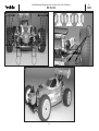
Bild 35, Karosserie (Bearbeitung siehe Seite 22)
Viel Spaß beim Testfahren!
Fig. 32 and 33, adjusting wheel camber:
- The camber of the wheels on an axle is normally set so
that the full width of the tyres makes contact with the
ground (model as supplied). Shortening the upper adju-
stable transverse arm applies negative camber to the
axle. This results in higher traction through turns, as the
car „leans into the bend“, but the drawback is that the
tyres wear faster and more unevenly since the contact
area is smaller. Positive camber results in reduced trac-
tion on the axle. We therefore recommend neutral or
slightly negative camber for off-road models.
- The basic rule is that any adjustments to the chassis
should always be carried out gradually, in small incre-
ments, and that the result of each change should be
tested thoroughly on the track. A carefully adjusted
chassis is just as important as a powerful motor if you
are looking for fast lap times.
Fig. 34, adjusting toe-in:
- The toe-in setting of the front axle affects the model’s
straight running characteristics and its steering respon-
se. With positive toe-in (drawing 1) the car has very
smooth, steady straight-running characteristics, and
responds relatively „softly“ to steering commands. If
you set negative toe-in (drawing 2), the car becomes
less directionally stable and responds more directly to
steering commands. As supplied the model is set up
with almost neutral toe-in (drawing 3) which provides
good straight running characteristics and normal stee-
ring response. Any changes to this setting should be
made in small increments.
Fig. 35, the body (trimming and painting see page 22)
Have fun testing!
Fig. 32 et 33, Réglage du carrossage :
- Normalement, le carrossage est réglé de telle manière
que les pneumatiques s’appuient de tote leur surface
sur le sol (c’est ainsi que le modèle est livré). Lorsqu’on
raccourcit le bras d’oscillation transversal du haut qui
est réglable, on obtient un carrossage négatif de l’axe
concerné. Ce réglage apporte une meilleure traction
dans le virages, étant donné que le modèle “se penche
dans les virage ”, mais il présente l’inconvénient d’une
usure irrégulière des pneumatiques étant donné que
leur surface d’appui au sol est moindre. Un carrossage
positif réduit la traction sur l’essieu. Sur un modèle de
tout terrain, il est donc recommandé de conserver un
carrossage neutre ou légèrement négatif.
- En principe, n’effectuer les réglages sur le train de
roulement qu’en procédant par petites étapes con-
trôlées systématiquement par de nombreux tours de
piste. Ce n’est pas que la puissance du moteur qui per-
met d’obtenir de bons chronos au tour mais également
un parfait réglage du train de roulement.
Fig. 34, Réglage du pincement des roues avant:
- Le réglage du pincement sur l’essieu avant a un effet
sur la trajectoire rectiligne du modèle et sur la sensibi-
lité de sa direction. Avec un pincement positif (repré-
sentation schématique 1) l’auto of
fre une trajectoire
rectiligne saine et réagit avec une certaine retenue aux
mouvements de la direction. Avec un pincement néga-
tif à l’avant (représentation schématique 2) la tenue de
trajectoire rectiligne est moins bonne et le modèle réa-
git très sensiblement aux instructions de direction. Le
modèle est livré avec une bonne tenue de trajectoire et
un comportement normal aux instructions de direction
avec un pincement avant pratiquement neutre (repré-
sentation schématique 3). Effectuer les réglages de
manière à rester dans des limites convenables.
Fig. 35, la carrosserie (finition cf. page 22)
Nous vous souhaitons beaucoup de plaisir pour vos
premières rondes!
No.
2028

Betriebsanleitung, Operating instructions instructions, Notice d’utilisation
RB 15/4 Kit
22
No.
2028
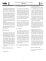
Bilder 36 - 40, Karosserie und Spoiler
Ausschnitte und Bohrungen für Motor, Schalldämpfer,
Karosseriebefestigung und Antenne anbringen.
Scheiben der Karosserie innen abkleben.
Die Karosseriebohrungen von außen mit Klebeband verschließen,
um ein Durchlaufen der Farbe zu verhindern.
Die gesamte Innenseite der Karosserie und den Spoiler mit feinem
Nassschleifpapier (Körnung 300) anschleifen. Karosserie innen mit
lauwarmem Seifenwasser reinigen, trocknen lassen und mit rocol-
or PC-Lack, Bestell Nr. je nach Farbe, lackieren. Äussere
Schutzhülle abziehen. Nach Trocknen der Farbe Klebeband
abziehen.
Dekorbilder abziehen, mit
Seifenwasser anfeuchten und auf der
Karosserie platzieren. Luftblasen mit einem weichen Lappen aus-
streichen.
Dekorbilder auf dem Spoiler aufbringen. Spoiler auf die Stützen
setzen und mit Splinten befestigen.
Karosserie aufsetzen und mit Splinten befestigen.
Figs. 36 - 40, the body and the spoiler
Cut the openings and holes required for the motor, silencer,
bodywork mounting and aerial.
Apply masking tape to the inside of the windows. Apply tape over
the outside of the bodywork openings to prevent the paint running
through.
Sand the whole of the inside of the bodywork and spoiler using
fine wet-and-dry paper (300-grit) to provide a “key” for the paint.
Wash out the inside of the moulding with luke-warm soapy water
and allow it to dry. The bodywork can now be painted using rocol-
or PC paint, Order No. according to colour. Peel off the external
protective film. Remove the tape again when the paint has dried.
Remove decal,
make slightly wet with soapy water and position
decals on bodywork, then smooth out air bubbles with a soft
cloth.
Apply the decals to the spoiler. Place the spoiler on the supports
and fix it in place using the split pins.
Place the body on the chassis and secure it with two split pins.
Figures 36 à 40, la carrosserie et l’aileron
Réaliser les alésages pour le moteur, le silencieux, la fixation de
la carrosserie et l'antenne.
Appliquer des morceaux du ruban adhésif à l’intérieur de la car-
rosserie avant de la peindre.
Boucher les orifices de la carrosserie de l’extérieur avec des
morceaux de ruban adhésif pour éviter que la peinture y passe.
Poncer l’intégralité de l’intérieur de la carrosserie et de l’aileron
avec du papier de verre humide (grain 300). Nettoyer l’intérieur de
la carrosserie à l’eau savonneuse tiède, la laisser sécher avant
d’appliquer la peinture rocolor PC, réf. en fonction de la teinte
choisie. Retirer le film protecteur extérieur. Retirer les morceaux
avant que la peinture ne soit complètement sèche.
Disposer les autocollants de décoration sur la carosserie,
après
les avoir humidifier avec de l'eau tiède savonneuse.
Débarasser des bulles d’air avec un chiffon humide.
Appliquer les autocollants de décoration. Installer l’aileron sur les
colonnettes et le fixer avec les goupilles.
Mettre la carrosserie en place et la fixer avec 2 goupilles.
37
38
39 40
36
La page est en cours de chargement...
La page est en cours de chargement...
La page est en cours de chargement...

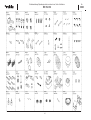
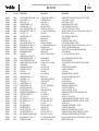
20171019
20171020
20171000
20171021
20171028
20171023
20171022
20171003
20171024
20171025
20171026
20171027
20171015
20171014
20171004
20171032
20171008
20171005
*
20171013
*
*
*
20171012
20171011
20171016
2
0171006
20171007
2
0171029
2
0171018
20171031
20171009
20171030
20171002
20171010
20171001
20171035
20171034
20171033
*
= 20171017
*
= 20171017
Betriebsanleitung, Operating instructions instructions, Notice d’utilisation
RB 15/4 Kit
26
No.
2028
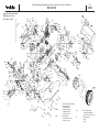
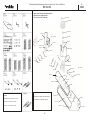
Explosionszeichnung: Verbrennungsmotor
Exploded view: glowplug motor
Vue eclatée: moteur thermique
S7025
20280028
Schraubenset:
siehe Explo Zeichn. Chassis
Screw set: see exploded view chassis
Jeu de vis: cf. vue eclatée du châssis
Motor komplett, No. 20171036
Glowplug motor complete, Order No. 20171036
Moteur thermique, complèt, réf. 20171036
La page est en cours de chargement...
La page est en cours de chargement...
La page est en cours de chargement...

Betriebsanleitung, Operating instructions instructions, Notice d’utilisation
RB 15/4 Kit
30
No.
2028
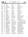
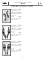
2-Ganggetriebe No. 20172000
42/46 Zähne, 1 Set
2-speed gearbox No. 20172000
42/46 teeth, 1 set
Mécanisme
à deux vitesses réf. 20172000
42/46 dents, 1 kit
Kupplungsglocke 17 Z No. 20172022
für höhere Endgeschwindigkeiten, 1 Stück
Clutch bell, 17 teeth No. 20172022
for high top speeds, pack of 1
Cloche d’embrayage
17 dents réf. 20172022
pour vitesses de pointe élevées, 1 pièce
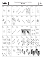
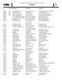
Tuningteile, Upgrade components, Équipement de compétition
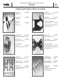
Alu-Bremsträger No. 20172014
Aluminium, CNC-gefräst, eloxiert, 1 Set
Aluminium brake carrier No. 20172014
Aluminium, CNC-machined, eloxided, 1 set
Porte-fr
ein en alu réf. 20172014
aluminium, fraisé sur machines à commande
numérique, anodisé, 1 kit
CFK RC-Platte No. 20172016
Kohlefaser, CNC-gefräst, 1 Stück
CFRP RC plate No. 20172016
Carbon fibre, CNC-machined, pack of 1
Platine de réception en plastique
renforcé fibre de carbone réf. 20172016
fibre de carbone, fraisée sur machines à com-
mande numérique, 1 pièce
CFK Zentral-Platte No. 20172017
Kohlefaser, CNC-gefräst, 1 Stück
CFRP central plate No. 20172017
Carbon fibre, CNC-machined, pack of 1
Plaque centrale en plastique
renforcé fibre de carbone réf. 20172017
fibre de carbone, fraisée sur machines à com-
mande numérique, 1 pièce
Alu-Felgenmitnehmer No. 20212018
Aluminium, CNC-gefräst 4 Stück
Aluminium wheel driver No. 20212018
Aluminium, CNC-machined pack of 4
Entraîneur de jante réf. 20212018
en aluminium
aluminium, fraisé sur machines
4 unités
à commande numérique

Betriebsanleitung, Operating instructions instructions, Notice d’utilisation
RB 15/4 Kit
31
No.
2028
Alu-Achsschenkel hinten No. 20172020
Aluminium, CNC-gefräst, eloxiert, 2 Stück
Aluminium rear stub axle No. 20172020
Aluminium, CNC-machined, eloxided, pack of 2
Fusée d'essieu
en alu arrière réf. 20172020
aluminium, fraisé sur machines à commande
numérique, anodisé, 2 pièces
Alu-Achsschenkelhalter vorne No. 20172019
Aluminium, CNC-gefräst, eloxiert, 2 Stück
Aluminium front stub axle holder No. 20172019
Aluminium, CNC-machined, eloxided, pack of 2
Porte-fusée d’essieu
en alu avant réf. 20172019
aluminium, fraisé sur machines à commande
numérique, anodisé, 2 pièces
Alu-Achsschenkel vorne No. 20172021
Aluminium, CNC-gefräst, eloxiert, 2 Stück
Aluminium front stub axle No. 20172021
Aluminium, CNC-machined, eloxided, pack of 2
Fusée d’essieu
en alu avant réf. 20172021
aluminium, fraisé sur machines à commande
numérique, anodisé, 2 pièces
Tuningteile, Upgrade components, Équipement de compétition

robbe Modellsport GmbH & Co. KG
Metzloserstr. 36
Telefon: 06644 / 87-0
D 36355 Grebenhain
BAF
Irrtum und technische Änderungen vorbehalten
Copyright robbe-Modellsport 2005
Kopie und Nachdruck, auch auszugsweise, nur mit schriftlicher
Genehmigung der robbe-Modellsport GmbH & Co.KG
Errors and omissions excepted. Modifications reserved.
Copyright robbe-Modellsport 2005
Copying and re-printing, in whole or in part, only with prior written
approval of robbe-Modellsport GmbH & Co. KG
Sous réserve de d’erreur et de modification technique.
Copyright robbe-Modellsport 2005
Copie et reproduction, même d’extraits, interdites sans autorisation
écrite expresse de la Société robbe-Modellsport GmbH & Co. KG
-
 1
1
-
 2
2
-
 3
3
-
 4
4
-
 5
5
-
 6
6
-
 7
7
-
 8
8
-
 9
9
-
 10
10
-
 11
11
-
 12
12
-
 13
13
-
 14
14
-
 15
15
-
 16
16
-
 17
17
-
 18
18
-
 19
19
-
 20
20
-
 21
21
-
 22
22
-
 23
23
-
 24
24
-
 25
25
-
 26
26
-
 27
27
-
 28
28
-
 29
29
-
 30
30
-
 31
31
-
 32
32


ROBBE RB 15/4 Kit Operating Instructions Manual
- Catégorie
- Jouets télécommandés
- Taper
- Operating Instructions Manual
dans d''autres langues
- English: ROBBE RB 15/4 Kit
- Deutsch: ROBBE RB 15/4 Kit
Documents connexes
-
ROBBE S3003 Operating Instructions Manual
-
-
-
-
-
-
-
-
-
ROBBE Air Beaver Instruction And User's Manual

