35/40,000 BTU/HR HEATER
PROPANE CONSTRUCTION FORCED AIR HEATER
OWNER’S MANUAL
IMPORTANT: Read and understand this manual before
assembling, starting or servicing heater. Improper use
of heater can cause serious injury. Keep this manual for
future reference.
GENERAL HAZARD WARNING:
Failure to comply with the precautions and instructions
provided with this heater, can result in death, serious
bodily injury and property loss or damage from hazards
of fire, explosion, burn, asphyxiation, carbon monoxide
poisoning and/or electrical shock.
Only persons who can understand and follow the instruc-
tions should use or service this heater.
If you need assistance or heater information such as an in-
structions manual, labels, etc. contact the manufacturer.
Save this manual for future reference.
For more information, visit www.desatech.com
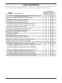
TABLE OF CONTENTS
Safety Information ............................................... 2
Unpacking ........................................................... 3
Product Identification ........................................... 3
Theory of Operation ............................................ 4
Propane Supply ................................................... 4
Installation ........................................................... 4
Ventilation ........................................................... 5
Operation ............................................................. 5
Storage ................................................................ 6
Maintenance ........................................................ 7
Service Procedures ............................................. 7
Specifications
..................................................... 9
Troubleshooting .................................................
10
Accessories ........................................................11
Technical Services ..............................................
11
Replacement Parts .............................................11
Illustrated Parts Breakdown and Parts List ....... 12
Warranty and Repair Service ..............
Back Cover

www.desatech.com
113855-01B
2
SAFETY INFORMATION
WARNING: This product
contains and/or generates
chemicals known to the State
of California to cause cancer or
birth defects or other reproduc-
tive harm.
WARNING: Fire, burn, in-
halation and explosion hazard.
Keep solid combustibles, such
as building materials, paper or
cardboard, a safe distance away
from the heater as recommend-
ed by the instructions. Never
use the heater in spaces which
do or may contain volatile or
airborne combustibles or prod
-
ucts such as gasoline, solvents,
paint thinner, dust particles or
unknown chemicals.
WARNING: Not for home or
recreational vehicle use.
The heater is designed for use as a construction heater
in accordance with ANSI Z83.7•CGA2.14-2000.
Other standards govern the use of fuel gases and
heating products for specific uses. Your local author-
ity can advise you about these. The primary purpose
of construction heaters is to provide temporary
heating of buildings under construction, alteration
or repair. Properly used, the heater provides safe
economical heating. Products of combustion are
vented into the area being heated.
We cannot foresee every use which may be made of
our heaters. Check with your local fire safety au
-
thority if you have questions about heater use.
Other standards govern the use of fuel gases and
heat producing products for specific uses. Your
local authorities can advise you about these.
Carbon Monoxide Poisoning: Some people are
more affected by carbon monoxide than others.
Early signs of carbon monoxide poisoning re-
semble the flu, with headaches, dizziness and/or
nausea. If you have these signs, the heater may not
be working properly. Get fresh air at once! Check
for proper ventilation and have heater serviced.
Propane Gas: Propane gas is odorless. An odor-
making agent is added to propane gas. The odor
helps you detect a propane gas leak. However, the
odor added to propane gas can fade. Propane gas
may be present even though no odor exists.
Make certain you read and understand all warn
-
ings. Keep this manual for reference. It is your
guide to safe and proper operation of this heater.
1. Install and use heater with care. Follow all
local ordinances and codes. In the absence
of local ordinances and codes, refer to the
Standard for Storage and Handling of Lique
-
fied Petroleum Gas, ANSI/NFPA 58 and the
Propane Gas Installation Code, CAN/CGA
B149.2. This instructs on the safe storage and
handling of propane gases.
2. Use only the electrical voltage and frequency
specified on model plate. The electrical con
-
nections and grounding of the heater shall fol
-
low the National Electric Code, ANSI/NFPA
70 or the Canadian Electrical Code, Part 1.
3. Electrical grounding instructions — This
appliance is equipped with a three-prong
(grounding) plug for your protection against
shock hazard and should be plugged directly
into a properly grounded three-prong recep
-
tacle or extension cord.
4. This product has been approved for use in the
Commonwealth of Massachusetts.
5. Use only a three-prong, grounded extension
cord.
6. Use only the hose and factory preset regulator
provided with the heater.
7. Use only propane gas set up for vapor with
-
drawal.
8. Provide adequate ventilation. Before using
heater, provide at least a 1.5 ft
2
(1400 cm
2
)
opening of fresh, outside air.
9. For indoor use only. Do not use heater
outdoors.
10. Do not use heater in occupied dwellings or in
living or sleeping quarters.
11. Do not use heater in basement or below ground
level. Propane gas is heavier than air. If a leak
occurs, propane gas will sink to the lowest
possible level.
12. Keep appliance area clear and free from com
-
bustible materials, gasoline, paint thinner and
other flammable vapors and liquids.
13. Do not use heater in areas with high dust
content. Dust is combustible.

www.desatech.com
113855-01B
3
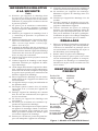
SAFETY INFORMATION
Continued
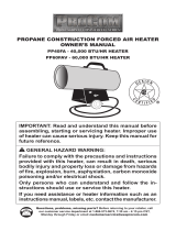
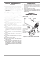
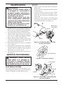
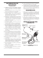
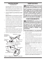
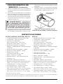
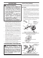
Hot Air Outlet
(Front)
Outer Shell
Motor
Power
Cord
Ignitor
Button
Automatic
Control Valve
Button
Hose/Regulator
Assembly
Handle
Figure 1 - 35,000 Btu/Hr Model Shown
14. Minimum heater clearances from combustibles:
Outlet: 6 Ft. (1.83 m), Sides: 2 Ft. (0.61 m),
Top: 6 Ft. (1.83 m), Rear: 2 Ft. (0.61 m)
15. Keep heater at least six feet from propane
tank(s). Do not point heater at propane tank(s)
within 20 feet.
16. Keep propane tank(s) below 100° F (37.8° C).
17. Check heater for damage before each use. Do
not use a damaged heater.
18. Check hose before each use of heater. If highly
worn or cut, replace with hose specified by
manufacturer before using heater.
19. Locate heater on stable and level surface if
heater is hot or operating.
20. Not intended for use on finished floors.
21. Never block air inlet (rear) or air outlet (front)
of heater.
22. Keep heater away from strong drafts, water
spray, rain or dripping water.
23. Do not leave heater unattended.
24. Keep children and animals away from
heater.
25. Never move, handle or service a hot, operating
or plugged-in heater. Severe burns may result.
You must wait 15 minutes after turning heater
off.
26. To prevent injury, wear gloves when handling
heater.
27. Never attach duct work to front or rear of
heater.
28. Do not alter heater. Keep heater in its original
state.
29. Do not use heater if altered.
30. Turn off propane supply and unplug heater
when not in use.
31. Use only original replacement parts. This
heater must use design-specific parts. Do
not substitute or use generic parts. Improper
replacement parts could cause serious or fatal
injuries.
UNPACKING
1. Remove all packing items applied to heater for
shipment. Keep plastic cover caps (attached to
inlet connector and hose/regulator assembly)
for storage.
2. Remove all items from carton.
3. Check all items for shipping damage. If heater
is damaged, promptly inform dealer where you
bought heater.
PRODUCT
IDENTIFICATION

www.desatech.com
113855-01B
4
INSTALLATION
WARNING: Review and under-
stand the warnings in the Safety
Information section, page 2. They
are needed to safely operate this
heater. Follow all local codes
when using this heater.
WARNING: Test all gas piping
and connections for leaks after
installation or servicing. Never
use an open flame to check for
a leak. Apply a mixture of liquid
soap and water to all joints.
Bubbles forming show a leak.
Correct all leaks at once.
1. Provide propane supply system (see Propane
Supply).
2. Connect POL fitting on hose/regulator as
-
sembly to propane tank(s). Turn POL fitting
counterclockwise into threads on tank. Tighten
firmly using wrench. IMPORTANT: Position
regulator so that hose leaving the regulator is
in a horizontal position (see Figure 3, page 5).
This places the regulator vent in the proper
position to protect it from the weather.
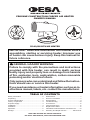
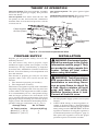
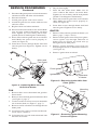
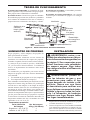
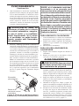
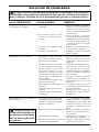
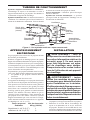
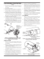
Figure 2 - Cross Section Operational View
Air For Combustion
Air For Heating
Clean Heated
Air Out (Front)
Fan
Motor
Cool
Air In
(Back)
Combustion
Chamber
Hose/Regulator
Assembly
THEORY OF OPERATION
The Fuel System: The hose/regulator assembly
attaches to the propane gas supply. This provides
fuel to the heater.
The Air System: The motor turns the fan. The
fan pushes air into and around the combustion
chamber. This air is heated and provides a stream
of clean, hot air.
The Ignition System: The piezo ignitor lights
the burner.
The Automatic Control System: This system causes
the heater to shut down if the flame goes out.
PROPANE SUPPLY
Propane gas and propane tank(s) are to be fur-
nished by the user.
Use this heater only with a propane vapor
withdrawal supply system. See Chapter 5 of the
Standard for Storage and Handling of Liquefied
Petroleum Gas, ANSI/NFPA 58
and/or CAN/CGA
B149.2. Your local library or fire department will
have this booklet.
The amount of propane gas ready for use from
propane tanks varies. Two factors decide this
amount:
1. The amount of propane gas in tank(s)
2. The temperature of tank(s)
This heater is designed to operate with a minimum
20 pound (9 kg) propane tank. You may need two
or more tanks or one larger tank in colder weather.
It is recommended you use a 100 pound (45 kg)
tank for longer operation. See chart below. Less
gas is vaporized at lower temperatures. Your local
propane gas dealer will help you select the proper
supply system. The minimum surrounding air tem
-
perature rating for each heater is 0° F (-18° C).
Average Temp No. Of Tanks
At Tank Location 100-pound (45 kg)
Above 0° F (-18° C) 1
Below 0° F (-18° C) 2

www.desatech.com
113855-01B
5
VENTILATION
WARNING: Provide at least
a 1.5 ft
2
(1400 cm
2
) opening of
fresh, outside air while running
heater. If proper fresh, outside
air ventilation is not provided,
carbon monoxide poisoning
can occur. Provide proper fresh,
outside air ventilation before
running heater.
OPERATION
WARNING: Review and under-
stand the warnings in the Safety
Information section, page 2. They
are needed to safely operate this
heater. Follow all local codes
when using this heater.
TO START HEATER
1. Follow all installation, ventilation and safety
information.
2. Locate heater on stable and level surface.
Make sure strong drafts do not blow into front
or rear of heater.
3. Plug power cord of heater into a three-prong,
grounded extension cord. Extension cord must
be at least six feet long. Extension cord must
be UL listed.
Extension Cord Wire Size Requirements
Up to 50 ft (15.24 m) long, use 18 AWG rated
cord.
51 to 100 ft (15.54 to 30.48 m) long, use 16
AWG rated cord.
101 to 200 ft (30.78 to 60.96 m) long, use 14
AWG rated cord.
4. Plug extension cord into a 120 volt/60 hertz,
3-hole, grounded outlet. Motor will start. Fan
will turn, forcing air out front of heater.
5. Open propane supply valve on propane
tank(s) slowly.
Note: If not opened slowly,
excess-flow check valve on propane tank will
stop gas flow. You may hear a click from the
excess-flow check valve closing. If this hap-
pens, reset the excess-flow check valve by
closing propane supply valve and open again
slowly.
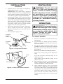
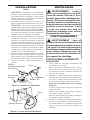
3. Connect hose to valve inlet (see Figure 4).
Tighten firmly using a wrench.
IMPORTANT: Use extra hose or piping if
needed. Install extra hose or piping between
hose/regulator assembly and propane tank. You
must use the regulator supplied with heater.
4. Open propane supply valve on propane tank(s)
slowly. Note: If not opened slowly, excess-flow
check valve on propane tank will stop gas flow.
You may hear a click from the excess-flow
check valve closing. If this happens, reset the
excess-flow check valve by closing propane
supply valve and open again slowly.
5. Check all connections for leaks. Apply mix
-
ture of liquid soap and water to gas joints.
Bubbles forming show a leak that must be
corrected.
6. Close propane supply valve.
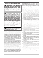
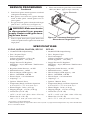
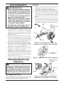
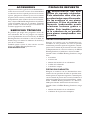
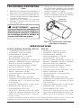
Figure 4 - Hose and Inlet Connector
Figure 3 - Regulator Position
Propane
Tank
Propane
Supply
Valve
Regulator
Hose
POL
Fitting
Hose
Inlet Connector
INSTALLATION
Continued

www.desatech.com
113855-01B
6
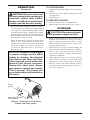
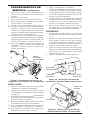
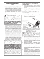
Piezo
Ignitor
Automatic Control
Valve Button
OPERATION
Continued
Figure 5 - Automatic Control Valve
Button and Piezo Ignitor
WARNING: Be sure motor and
fan are running before pushing in
automatic control valve button.
Flames could flash outside heater
if motor and fan are not running.
6. Push in and hold automatic control valve but-
ton (see Figure 5). Push piezo ignitor button
(see Figure 5). Keep pushing ignitor button
until the burner lights. When burner lights,
keep automatic control valve button pushed in.
Release button after 30 seconds. This activates
the automatic control system.
Note: If heater fails to ignite, hose may have
air in it. If so, keep automatic control valve
button pressed and wait 20 seconds. Release
automatic control valve button and wait 20
seconds for unburned fuel to exit heater.
Repeat this step.
NOTICE: If heater is unplugged
or power outage occurs while
heater is running, the thermal
limit device will stop fuel flow.
A few seconds occur before the
thermal limit device activates.
During this short time, flames
may appear outside the heater.
This is normal. The flames will
go out when thermal limit device
activates.
TO STOP HEATER
1. Tightly close propane supply valve on propane
tank(s).
2. Wait a few seconds. Heater will burn gas left
in supply hose.
3. Unplug heater.
TO RESTART HEATER
1. Wait five minutes after stopping heater.
2. Repeat steps under To Start Heater
, page 5.
STORAGE
CAUTION: Disconnect heater
from propane supply tank(s).
1. Store propane tank(s) in safe manner. See
Chapter 5 of Standard for Storage and Han
-
dling of Liquefied Petroleum Gases, ANSI/
NFPA 58. Follow all local codes. Always store
propane tanks outdoors.
2. Place plastic cover caps over brass fittings on
inlet connector and hose/regulator assembly.
3. Store in dry, clean and safe place. Do not
store hose/regulator assembly inside heater
combustion chamber.
4. When taking heater out of storage, always
check inside of heater. Insects and small
animals may place foreign objects in heater.
Remove motor and other internal parts if
needed to remove foreign objects (see Service
Procedures,
page 7).

www.desatech.com
113855-01B
7
MAINTENANCE
WARNINGS
• Never service heater while it
is plugged in, connected to
propane supply, operating or
hot. Severe burns and electri-
cal shock can occur.
• Keep heater clear and free
from combustible materials,
gasoline and other flammable
vapors and liquids.
• Do not block the flow of com-
bustion or ventilation air.
1. Keep heater clean. Clean heater annually or as
needed to remove dust and debris. If heater is
dirty or dusty, clean heater with a damp cloth.
Use household cleaners on difficult spots.
2. Inspect heater before each use. Check connec
-
tions for leaks. Apply mixture of liquid soap
and water to connections. Bubbles forming
show a leak. Correct all leaks at once.
3. Inspect hose/regulator assembly before each
use. If hose is highly worn or cut, replace with
hose specified by manufacturer.
4. Have heater inspected yearly by a qualified
service agency.
5. Keep inside of heater free from combustible
and foreign objects. Remove motor and other
internal parts if needed to clean inside of
heater (see Service Procedures).
6. Clean fan blades each season or as needed (see
Fan, page 8).
SERVICE PROCEDURES
WARNING: Never service
heater while it is plugged in,
connected to propane supply,
operating or hot. Severe burns
and electrical shock can occur.
ELECTRICAL SYSTEM
The entire electrical system for this heater is con-
tained within the motor. If any part of the electrical
system is damaged, you must replace motor.
Screw
Screw
Motor and
Fan Guard
MOTOR
1. Remove three screws that attach fan guard to
heater shell.
2. Remove motor and fan guard from heater shell
(see Figure 6).
3. Use hex wrench to loosen set screw which
holds fan to motor shaft (see Figure 7). Re
-
move fan. Be careful not to damage the fan
blade pitch.
4. Remove two nuts and two screws that attach
fan guard to motor using nut-driver. Remove
fan guard from motor (see Figure 8).
Figure 6 - Removing Motor and Fan
Guard from Heater
Figure 7 - Setscrew Location
Setscrew
Figure 8 - Removing or Attaching Fan
Guard from Motor
Fan Guard
Motor
Screw

www.desatech.com
113855-01B
8
Figure 9 - Replacing Motor and Fan
Guard Into Heater
SERVICE PROCEDURES
Continued
Figure 11 - Removing Ignitor Mounting
Screw and Ignitor
Figure 10 - Removing Ignitor Wire from
Piezo Ignitor
Ignitor
Mounting
Screw
Ignitor Wire
Piezo Ignitor
Underside
of Heater
Motor and
Fan Guard
Screw
Screw
5
Disconnect the green power cord wire from motor
and remove black and white wire terminals.
6. Discard old motor.
7. Attach green power cord wire to motor.
8. Attach fan guard to new motor with two nuts
and two screws.
9. Replace black and white terminals.
10. Place fan onto motor shaft of new motor. Make
sure set screw contacts flat surface on motor
shaft. Tighten set screw firmly (40-50 inch-
pounds [46.08-57.60 kilogram-centimeters]).
11. Place motor and fan guard into rear of heater
shell. Make sure power cord is properly lo
-
cated (see Figure 9).
12. Insert three screws through heater shell and
into fan guard (see Figure 9). Tighten screws
firmly.
FAN
1. Remove three screws that attach fan guard to
heater shell.
2. Remove motor and fan guard from heater shell
(see Figure 6, page 7).
3. Use hex wrench to loosen set screw that holds
fan to motor shaft (see Figure 7, page 7).
4. Remove fan. Be careful not to damage the fan
blade pitch.
5a. If replacing fan, remove old fan and discard.
Go to step 7, column 2.
5b. If cleaning fan, use soft cloth moistened with
kerosene or solvent.
6. Dry fan thoroughly.
7. Place fan onto motor shaft. Make sure set
screw contacts flat surface on motor shaft.
Tighten set screw firmly (40-50 inch-pounds
[46.08-57.60 kilogram-centimeters]).
8. Place motor and fan guard into rear of heater
shell. Make sure power cord is properly lo
-
cated (see Figure 9).
9. Insert three screws through heater shell and
into fan guard. Tighten screws firmly.
IGNITOR
1. Remove motor and fan guard from heater (see
Motor, page 7, steps 1 and 2).
2. Remove black ignitor wire from piezo ignitor.
Access ignitor wire through underside of
heater base (see Figure 10). Push wire up
through notch in filler panel.
3. Remove ignitor mounting screw from rear
head using nut-driver or standard screwdriver
(see Figure 11).
4. Remove ignitor from rear head.

www.desatech.com
113855-01B
9
Figure 12 - Clearance Between Ignitor
Electrode and Target Plate
Ignitor Electrode
Gap
Area
SPECIFICATIONS
5. Install new ignitor. Attach ignitor to rear head
with ignitor mounting screw.
6. Run ignitor wire from new ignitor through
notch in filler panel. Attach ignitor wire to
piezo ignitor.
7. Set gap between ignitor electrode and target
plate to 0.17" (43.18 cm) (see Figure 12).
WARNING: Make sure heater
is disconnected from propane
supply. Heater could ignite caus-
ing severe burns.
8. Test for spark. Push piezo ignitor button and
watch for spark between ignitor electrode and
target plate.
SERVICE PROCEDURES
Continued
9. Place motor and fan guard into rear of heater
shell (see Motor, page 8, steps 9 and 10).
SPC-40
• 40,000 BTU/Hr Output Rating
• Fuel - Propane Vapor
• Fuel Consumption
Gallons (liters)/Hour - 0.44 (1.65)
Pounds (kg)/Hour - 1.86 (0.84)
• Supply Pressure To Regulator
Minimum* - 20 psi, Maximum - Tank Pressure
or 200 psi
• Regulator Outlet Pressure - 10 PSI
• Manifold Pressure - 10 PSI
• Hot Air Output (CFM Approx) - 100
• Motor - 3045 RPM, 1/40 HP
• Electric Input - 120 volt/60 hertz
• Amperage - .6
• Ignition - Manual, Piezo
• Temperature Range for Heater Operation
0° F to 85° F** (-17° C to 29.4° C)**
• Heater Weight - 14 lbs. (6.35 kg)
• Shipping Weight - 15.3 lbs. (6.94 kg)
• Carton Size (L x W x H)
19.75" x 11.25" x 14" (50.2 x 28.6 x 35.6 cm)
• Heater Size (L x W x H)
18.5" x 7.7" x 12.8" (47 x 19.6 x 32.5 cm)
* For purposes of input adjustment
** When running heater in temperatures above 85° F (29.44° C), high internal temperatures may cause thermal limit
device to shut down heater.
35-FAC, NLP35A, RLLP35A, SPC-35
• 35,000 BTU/Hr Output Rating
• Fuel - Propane Vapor
• Fuel Consumption
Gallons (liters)/Hour - 0.38 (1.44)
Pounds (kg)/Hour - 1.62 (0.74)
• Supply Pressure To Regulator
Minimum* - 20 psi, Maximum - Tank Pressure
or 200 psi
• Regulator Outlet Pressure - 10 PSI
• Manifold Pressure - 10 PSI
• Hot Air Output (CFM Approx) - 100
• Motor - 3045 RPM, 1/40 HP
• Electric Input - 120 volt/60 hertz
• Amperage - .6
• Ignition - Manual, Piezo
• Temperature Range for Heater Operation
0° F to 85° F** (-17° C to 29.4° C)**
• Heater Weight - 14 lbs. (6.35 kg)
• Shipping Weight - 15.3 lbs. (6.94 kg)
• Carton Size (L x W x H)
19.75" x 11.25" x 14" (50.2 x 28.6 x 35.6 cm)
• Heater Size (L x W x H)
18.5" x 7.7" x 12.8" (47 x 19.6 x 32.5 cm)

www.desatech.com
113855-01B
10
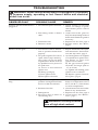
TROUBLESHOOTING
WARNING: Never service heater while it is plugged in, connected
to propane supply, operating or hot. Severe burns and electrical
shock can occur.
REMEDY
1. Check voltage to electrical
outlet. If voltage is good,
check heater power cord for
breaks
2. Adjust motor/fan guard to
keep fan from hitting inside of
heater shell. Bend fan guard if
necessary
3. Replace fan. See
Fan, page 8
4. Replace motor. See Motor
,
page 7
1. Repeat installation and opera
-
tion instructions. See Installa
-
tion and Operation, page 5
2. A) Check ignitor wire. Tighten
or reattach loose ignitor wire.
See Figure 11, page 8 for
ignitor wire location
B) Set gap between ignitor
electrode and target plate to
.17" (0.43 cm)
C) Tighten nut holding piezo
ignitor to base of heater
D) Replace ignitor electrode.
See Ignitor, page 8
1. This can happen when running
heater in temperatures above
85°F (29.44° C). Run heater
in cooler temperatures
2 Check heater inlet and outlet.
Remove any obstructions
3. Replace fan. See
Fan, page 8
4. Clean heater. See Mainte
-
nance, page 7
OBSERVED FAULT
Fan does not turn when heater is
plugged in
Heater will not ignite
Heater shuts down while run-
ning
POSSIBLE CAUSE
1. No electrical power to heater
2. Fan hitting inside of heater
shell
3. Fan blades bent
4. Defective motor
1. User did not follow installa
-
tion or operation instructions
properly
2. No spark at ignitor. To test for
spark, follow step 8 under
Ig-
nitor, page 9. If you see spark
at ignitor, have heater serviced
by qualified service person. If
no spark seen:
A) Loose or disconnected
ignitor wire
B) Wrong spark gap
C) Piezo ignitor loose
D) Bad ignitor electrode
1. High surrounding air tem
-
perature causing thermal limit
device to shut down heater
2. Restricted air flow
3. Damaged fan
4. Excessive dust or debris in
surrounding area
WARNING: Use only in areas
free of high dust content.

www.desatech.com
113855-01B 11
ACCESSORIES
Purchase accessories and parts from your nearest
dealer or service center. If your dealer or service
center can not supply an accessory or part, either
contact your nearest Parts Central (listed in the
separate Authorized Service Center booklet) or
call DESA Heating Products at 1-866-672-6040
for referral information. You can also write to the
address listed on the back page of this manual.
TECHNICAL SERVICES
You may have further questions about this heater.
If so, contact DESA Heating Productsʼ Technical
Service Department at 1-866-672-6040. When
calling, please have your model and serial numbers
of your heater ready.
You can also visit DESA Heating Productsʼ Techni
-
cal Service web site at www.desatech.com.
REPLACEMENT PARTS
WARNING: Use only original
replacement parts. This heater
must use design-specific parts.
Do not substitute or use generic
parts. Improper replacement
parts could cause serious or fa-
tal injuries. This will also protect
your warranty coverage for parts
replaced under warranty.
PARTS UNDER WARRANTY
Contact authorized dealers of this product. If they
canʼt supply original replacement part(s), either
contact your nearest Parts Central or call DESA
Heating Productsʼ Technical Service Department
at 1-866-672-6040.
When calling DESA Heating Products, have
ready
• your name
• your address
• model number of your heater
• how heater was malfunctioning
• purchase date
PARTS NOT UNDER WARRANTY
Contact authorized dealers of this product. If
they canʼt supply original replacement part(s),
either contact your nearest Parts Central (listed in
Authorized Service Center booklet) or call DESA
Heating Products at 1-866-672-6040 for referral
information.
When calling DESA Heating Products, have
ready
• model number of your heater
• the replacement part number

www.desatech.com
113855-01B
12
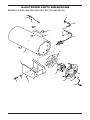
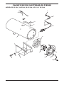
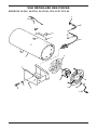
ILLUSTRATED PARTS BREAKDOWN
MODELS 35-FAC, NLP35A, RLLP35A, SPC-35 AND SPC-40
3
4
12
13
16
14
15
8
6
7
9
5
11
10
1
2
5

www.desatech.com
113855-01B
13
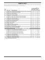
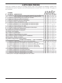
PARTS LIST
This list contains replaceable parts used in your heater. When ordering parts, follow the instructions
listed under Replacement Parts on page 11 of this manual.
KEY
NO. PART NO. DESCRIPTION QTY.
1 113832-01 Heater Body Kit (Replacement kit will be unpainted) • • • • • 1
2 113833-01 Control Box Assembly • • • • • 1
3 102445-01 Piezo Ignitor • • • • • 1
4 102334-01 Palnut Fastner • • • • • 1
5 113852-01 Hex Nut, 5-28 • • • • • 1
6 113834-01 Valve with Thermocouple Assembly • • • • 1
113834-02 Valve with Thermocouple Assembly • 1
7 113846-01 Wire Assembly • • • • • 1
8 115324-01 Thermal Switch Kit • • • • • 1
9 113847-01 Electrode Ignitor • • • • • 1
10 097918-01 Handle Clip • • • • • 2
11
097917-01 Handle • • • • • 1
12 113851-01 Fan • • • • • 1
13 113849-01 Motor Assembly • • • • • 1
14 113850-01 Fan Guard • • • • • 1
15 M11143-1 Bushing, Strain Relief • • • • • 1
16 098219-25 Cord, Power Supply • • • • • 1
PARTS AVAILABLE - NOT SHOWN
113835-01 Hose/Regulator Assembly • • • • • 1
113858-01 Tradename Decal (SPC-35, SPC-40)
• • 2
113858-02 Tradename Decal (35-FAC)
• 2
113858-04 Tradename Decal (NLP35A)
• 2
109111-02 Tradename Decal (RLLP35A)
• 2
113853-01 Warning Decal
• • • • • 1
113854-01
Operation Decal • • • • • 1
113802-03
Model Data Decal • • • • 1
113802-04
Model Data Decal • 1
** Not a field replaceable part.
RLLP35A
SPC-40
SPC-35
NLP35A
35-FAC

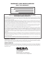
2701 Industrial Drive
P.O. Box 90004
Bowling Green, KY 42102-9004
ATTN: Customer Service Department
WARRANTY AND REPAIR SERVICE
KEEP THIS WARRANTY
LIMITED WARRANTIES FOR NEW AND FACTORY
RECONDITIONED PRODUCTS
New Products: DESA Heating Products warrants this heater and any parts thereof, to be free of defects in materials
and workmanship for one (1) year from the date of first purchase, when operated and maintained in accordance
with the manufacturer's instructions. These warranties are extended only to the original retail purchaser, when
proof of purchase is provided.
Factory Reconditioned Heaters: DESA Heating Products warrants this factory reconditioned heater and any parts
thereof, to be free of defects in materials and workmanship for thirty (30) days from the date of first purchase,
when operated and maintained in accordance with the manufacturer's instructions. These warranties are extended
only to the original retail purchaser, when proof of purchase is provided.
These warranties cover only the cost of parts and labor required to restore the product to proper operating condition.
Transportation and incidental costs associated with warranty repairs are not reimbursable under this warranty.
Warranty service is available only through authorized dealers and service centers.
This warranty does not cover defects resulting from misuse, abuse, negligence, accidents, lack of proper mainte
-
nance, normal wear, alteration, modification, tampering, contaminated fuels, repair using improper parts or repair by
anyone other than an authorized dealer or service center. Routine maintenance is the responsibility of the owner.
THIS EXPRESS WARRANTY IS GIVEN IN LIEU OF ANY OTHER WARRANTY EITHER EXPRESSED
OR IMPLIED, INCLUDING WARRANTIES OF MERCHANTABILITY AND FITNESS FOR A PARTICULAR
PURPOSE.
DESA Heating Products assumes no responsibility for indirect, incidental or consequential damages. Some states
do not allow the exclusion or limitation of incidental or consequential damages or limitations or exclusions may
not apply to you. This limited warranty gives you specific legal rights and you may also have other rights which
vary from state to state.
We reserve the right to amend these specifications at any time without notice. The only warranty applicable is our
standard written warranty. We make no other warranty, expressed or implied.
WARRANTY SERVICE
Should your heater require service, return it to your nearest authorized service center. Proof of purchase must be
presented with the heater. The heater will be inspected. A defect may be caused by faulty materials or workman
-
ship. If so, DESA Heating Products will repair or replace the heater without charge.
REPAIR SERVICE
Return your heater to your nearest authorized service center. Repairs not covered by the warranty will be billed at
standard prices. Each Service Center is independently owned and operated. We reserve the right to amend these
specifications at any time without notice. When writing, always include model number and serial number. For
information, write:
Model
Serial No.
Date of Purchase

CALENTADOR DE 35/40,000 BTU/H
CALENTADOR DE AIRE FORZADO DE PROPANO PARA
CONSTRUCCIÓN
MANUAL DEL PROPIETARIO
IMPORTANTE: lea y comprenda este manual antes de
ensamblar, encender o dar servicio al calentador. El uso
inadecuado del calentador puede ca usar lesiones graves.
Conserve este manual para referencias futuras.
ADVERTENCIA GENERAL DE PELIGRO:
El incumplimiento de las precauciones e instrucciones
proporcionadas con este calentador puede causar la
muerte, lesiones físicas graves y pérdidas o daños a la
propiedad ocasionados por incendios, explosiones, que-
maduras, asfixia, intoxicación con monóxido de carbono
y/o electrocución.
Únicamente las personas que puedan entender y seguir las
instrucciones deberán usar o dar servicio a este calentador.
Si necesita ayuda o información sobre el calentador, como
por ejemplo un manual de instrucciones, etiquetas, etc.,
comuníquese con el fabricante.
Guarde este manual para referencias futuras.
Para obtener más información, visite www.desatech.com
TABLA DE CONTENIDO
Información de seguridad .................................... 2
Desempaque ....................................................... 3
Identificación del producto ................................... 3
Teoría de funcionamiento ....................................
4
Suministro de propano ........................................ 4
Instalación ........................................................... 4
Ventilación ...........................................................
5
Funcionamiento ................................................... 5
Almacenamiento .................................................. 6
Mantenimiento ..................................................... 7
Procedimientos de servicio ................................. 7
Especificaciones .................................................. 9
Solución de problemas ..................................... 10
Accesorios ..........................................................11
Servicios técnicos ...............................................11
Piezas de repuesto .............................................11
Clasificación ilustrada de piezas y lista de piezas ...12
Garantía y servicio de reparación ..................... 14

www.desatech.com
113855-01B
2
INFORMACIÓN DE SEGURIDAD
ADVERTENCIA: este produc-
to contiene y/o genera químicos
reconocidos por el Estado de Ca-
lifornia como causantes de cáncer
o de defectos de nacimiento, u
otros daños reproductivos.
ADVERTENCIA: peligro de
incendio, quemaduras, inhalación
y explosión. Mantenga los com-
bustibles sólidos, como materiales
de construcción, papel o cartón a
una distancia segura del calentador
según se recomienda en las instruc-
ciones. Nunca use el calentador en
áreas que contengan o que puedan
contener combustibles volátiles o
que se acumulan en el aire o bien
productos como gasolina, solventes,
diluyente de pintura, partículas de
polvo o químicos desconocidos.
ADVERTENCIA: no usar en
residencias ni en vehículos re-
creativos.
El calentador está diseñado para usarse como calen-
tador para construcción conforme a la norma ANSI
Z83.7•CGA2.14-2000. Otras normas rigen el uso
de gases combustibles y productos de calefacción
para usos específicos. La autoridad local puede
informarle acerca de éstas. El propósito principal de
los calentadores para construcción es proporcionar
calentamiento temporal de edificios en construc-
ción, modificación o reparación. Cuando se usa
correctamente, el calentador proporciona calefacción
económica y segura. Los productos de combustión se
ventilan al área que se está calentando.
No podemos prever todos los usos que se les pueden
dar a nuestros calentadores. Consulte a la autoridad
local de seguridad contra incendios si tiene pre
-
guntas acerca del uso de calentadores.
Otras normas rigen el uso de gases combustibles y
productos que producen calor para usos específicos. Las
autoridades locales pueden informarle acerca de éstas.
Intoxicación con monóxido de carbono: el monóxi-
do de carbono afecta más a algunas personas que a
otras. Los primeros signos de intoxicación con mo-
nóxido de carbono son semejantes a los de la gripe,
con dolor de cabeza, mareo o náusea. Si usted pre-
senta estos síntomas, es posible que el calentador no
esté funcionando correctamente. ¡Respire aire fresco
inmediatamente! Compruebe que haya ventilación
adecuada y haga que reparen el calentador.
Gas propano: el gas propano es inodoro. Al gas pro-
pano se le agrega un agente con olor. El olor le ayuda
a detectar las fugas de gas propano. Sin embargo, el
olor que se añade al gas propano puede desvanecerse.
Es posible que haya gas propano presente aunque no
haya ningún olor.
Asegúrese de leer y comprender todas las adver
-
tencias. Conserve este manual como referencia. Es
su guía para la operación segura y correcta de este
calentador.
1. Instale y use el calentador cuidadosamente. Siga
las ordenanzas y los códigos locales. A falta de
decretos y códigos locales, consulte la
Norma
de almacenamiento y manejo de gas licuado
de petróleo, ANSI/NFPA 58 y el Código de
instalación de gas propano, CAN/CGA B149.2.
Ésta proporciona instrucciones acerca del alma
-
cenamiento y manejo seguro del propano.
2. Use solamente la tensión eléctrica y la frecuen
-
cia especificados en la placa del modelo. Las
conexiones eléctricas y de tierra del calentador
deberán estar de acuerdo al Código eléctrico
nacional, ANSI/NFPA 70 o al Código eléctrico
canadiense, parte 1.
3. Instrucciones para la conexión eléctrica a tierra:
este aparato está equipado con un enchufe de tres
clavijas (con conexión a tierra) para protegerlo
contra el riesgo de descargas eléctricas y se tiene
que conectar directamente a un enchufe de pared
o un cable de extensión de tres ranuras conectado
a tierra correctamente.
4. Este producto ha sido aprobado para su uso en
el Estado de Massachusetts.
5. Use solamente un cable de extensión con co
-
nexión a tierra de tres clavijas.
6. Use sólo la manguera y el regulador preinstalado
en la fábrica que se incluyen con el calentador.
7. Use solamente el montaje de gas propano para
la extracción de vapores.
8. Proporcione una ventilación adecuada. Antes de
usar el calentador, proporcione una abertura de
aire fresco del exterior de al menos 1400 cm
2
(1.5 pies
2
).
9. Para uso en interiores solamente. No use el
calentador en exteriores.
10. No use el calentador en viviendas ocupadas ni
en dormitorios o alojamientos.
11. No use el calentador en un sótano ni debajo del
nivel del suelo. El gas propano es más pesado
que el aire. Si se produce una fuga, el gas pro
-
pano se asentará en el nivel más bajo posible.

www.desatech.com
113855-01B
3
INFORMACIÓN DE
SEGURIDAD
Continuación
Salida de aire
caliente (parte
anterior)
Cubierta exterior
Motor
Cable de
alimentación
Botón del
encendido
Botón de la
válvula de control
automático
Ensamblaje
de manguera-
regulador
Manija
Figura 1 - Se muestra el modelo de
35,000 BTU/h
12. Mantenga el área cerca del aparato despejada
y libre de materiales combustibles, gasolina,
diluyentes para pintura y otros vapores y líquidos
inflamables.
13. No use el calentador en áreas con un alto conte
-
nido de polvo. El polvo es combustible.
14. Distancia mínima entre el calentador y el com
-
bustible: enchufe: 1.83 m (6 pies), laterales: 2
pies (60.96 cm), parte superior: 1.83 m (6 pies),
parte posterior: 60.96 m (2 pies)
15. Mantenga el calentador alejado de los tanques
de propano a una distancia de al menos 1,8 m
(6 pies). No apunte el calentador hacia tanques
de propano que se encuentren a una distancia
menor de 6 m (20 pies).
16. Mantenga los tanques de propano por debajo de
los 37.8º C (100° F).
17. Antes de cada uso, verifique si el calentador ha su
-
frido algún daño. No use un calentador dañado.
18. Revise la manguera antes de cada uso del calen
-
tador. Si la manguera está muy desgastada o con
roturas, reemplácela con una manguera especifi
-
cada por el fabricante antes de usar el calentador.
19. Sitúe el calentador en una superficie estable y
nivelada si el calentador está caliente o si está
funcionando.
20.
No está diseñado para su uso en pisos terminados.
21. Nunca bloquee la entrada de aire (parte posterior)
ni la salida de aire (parte anterior) del calentador.
22. Mantenga el calentador alejado de corrientes
fuertes de aire, rocío, lluvia o goteos de agua.
23. No deje el calentador desatendido.
24. Evite que los niños y los animales se acerquen
al calentador.
25. Nunca mueva, maneje o repare un calentador en
funcionamiento, caliente, o conectado. Pueden
producirse quemaduras graves. Debe esperar 15
minutos después de apagar el calentador.
26. Para evitar lesiones, use guantes cuando mani
-
pule el calentador.
27. Nunca conecte conductos a la parte anterior o
posterior del calentador.
28. No altere el calentador. Mantenga el calentador
en su estado original.
29. No use el calentador si éste ha sido alterado.
30. Cierre el suministro de propano al calentador y
desconéctelo cuando no se esté usando.
31. Use sólo piezas de repuesto originales. Este
calentador debe usar piezas diseñadas específica
-
mente. No las sustituya ni use piezas genéricas.
El uso de piezas de repuesto inadecuadas puede
ocasionar lesiones graves o fatales.
DESEMPAQUE
1. Retire todos los elementos de empaque que
acompañan al calentador para su envío. Man-
tenga los tapones de plástico (fijados al ensam
-
blaje de manguera-regulador y al conector de
entrada) puestos cuando se guarde.
2. Saque todos los elementos de la caja.
3. Revise todos los elementos para ver si hay da
-
ños debidos al transporte. Si el calentador está
dañado, informe de inmediato al distribuidor
a quien se lo compró.
IDENTIFICACIÓN DEL
PRODUCTO

www.desatech.com
113855-01B
4
INSTALACIÓN
ADVERTENCIA: revise y en-
tienda las advertencias en la sec-
ción Información de seguridad, en
la página 2. Son necesarias para
hacer funcionar este calentador
de manera segura. Siga todos
los códigos locales al utilizar este
calentador.
ADVERTENCIA: pruebe to-
das las tuberías de gas y sus
conexiones para saber si hay
fugas después de instalar o dar
servicio. Nunca use una llama
al descubierto para verificar una
fuga. Aplique una mezcla de jabón
líquido y agua en todas las unio
-
nes. La formación de burbujas
indicará una fuga. Repare todas
las fugas inmediatamente.
1. Proporcione un sistema de suministro de propano
(consulte Suministro de propano).
2. Conecte el niple de rosca invertida del ensambla
-
je de manguera-regulador a los tanques de pro-
pano. Gire el niple de rosca invertida en sentido
contrario al de las manecillas del reloj en la rosca
Figura 2 - Vista transversal de funcionamiento
Air For Combustion
Air For Heating
Salida de aire
caliente y
limpio (parte
anterior)
Ventilador
Motor
Entrada
de aire
frío (parte
posterior)
Cámara de
combustión
Ensamblaje
de manguera-
regulador
TEORÍA DE FUNCIONAMIENTO
El sistema de combustible: el ensamblaje de man-
guera-regulador se fija al suministro del gas propano.
Esto proporciona combustible al calentador.
El sistema de aire: el motor hace girar el ventilador.
El ventilador proporciona aire al interior y alrededor
de la cámara de combustión. Este aire se calienta y
proporciona una corriente de aire limpio y caliente.
El sistema de encendido: el encendido piezoeléc-
trico enciende el quemador.
El sistema de control automático: este sistema
ocasiona que el calentador se apague si se extingue
la llama.
SUMINISTRO DE PROPANO
El gas propano y el(los) tanque(s) de propano los
debe aprovisionar el usuario.
Use el calentador solamente con un sistema de
suministro con extracción de vapores de propano.
Consulte el capítulo 5 de la Norma de almacenamien
-
to y manejo de gas licuado de petróleo, ANSI/NFPA
58 y/o la norma CAN/CGA B149.2. La biblioteca
local o el departamento de bomberos debe tener
este folleto.
La cantidad de gas disponible para usarse de los
tanques de propano varía. Dos factores determinan
esta cantidad:
1. La cantidad de gas propano en el (los) tanque(s)
2. La temperatura del(de los) tanque(s)
Este calentador está diseñado para funcionar con un
tanque de al menos 9 kg (20 libras). Es posible que
necesite dos o más tanques o un tanque de mayor
tamaño durante clima frío. Se recomienda que use
un tanque de 45 kg (100 libras) para periodos de
funcionamiento más largos. Consulte la tabla a conti
-
nuación. A temperaturas más bajas se vaporiza menos
gas. Su proveedor local de gas propano le ayudará
a seleccionar el sistema de suministro adecuado. La
temperatura mínima del aire circundante de cada
calentador es de -18° C (0° F).
Temperatura promedio
en la ubicación No. de tanques
del tanque 45 kg (100 libras)
Superior a -18° C (0° F) 1
Inferior a -18° C (0° F) 2
Aire para calefacción
Aire para la
combustión

www.desatech.com
113855-01B
5
VENTILACIÓN
ADVERTENCIA: procure tener
al menos una abertura de aire
fresco del exterior de 1400 cm
2
(1.5
pies
2
) mientras el calentador está
encendido. Si no se proporciona
una ventilación de aire fresco del
exterior, puede haber una intoxi-
cación con monóxido de carbono.
Proporcione una ventilación ade
-
cuada de aire fresco del exterior
antes de encender el calentador.
FUNCIONAMIENTO
ADVERTENCIA: revise y en-
tienda las advertencias en la sec
-
ción Información de seguridad, en
la página 2. Son necesarias para
hacer funcionar este calentador
de manera segura. Siga todos los
códigos locales al utilizar este
calentador.
PARA ENCENDER EL CALENTADOR
1. Siga toda la información de instalación, venti-
lación y seguridad.
2. Sitúe el calentador sobre una superficie estable
y nivelada. Asegúrese de que no haya corrientes
fuertes de aire entrando en la parte anterior o
posterior del calentador.
3. Conecte el cable de alimentación del calentador
a un cable de extensión con conexión a tierra de
tres clavijas. El cable de extensión debe tener al
menos 1.8 m (6 pies) de longitud. El cable de
extensión debe estar aprobado en la lista de UL.
Requisitos de medida del cable de
extensión
Hasta 15.24 m (50 pies) de largo, use cable de
calibre 18 AWG.
De 15.54 a 30.48 m (de 51 a 100 pies) de largo,
use cable de calibre 16 AWG.
De 30.78 a 60.96 m (de 101 a 200 pies) de
largo, use cable de calibre 14 AWG.
4. Conecte el cable de extensión a un enchufe
con conexión a tierra de tres orificios de 120
voltios/60 hercios. El motor arrancará. El
ventilador se encenderá, haciendo que el aire
salga por la parte anterior del calentador.
del tanque. Apriete firmemente usando una llave.
IMPORTANTE: coloque el regulador de manera
que la manguera que sale del regulador esté en
posición horizontal (consulte la figura 3). Esto
coloca la ventila del regulador en la posición
correcta para protegerla de la intemperie.
3. Conecte la manguera a la entrada de la válvula
(consulte la figura 4). Apriete firmemente usando
una llave.
IMPORTANTE: use una manguera o tubería
adicional si es necesario.Instale la manguera o
tubería adicional entre el ensamblaje de mangue-
ra-regulador y el tanque de propano.Debe usar
el regulador que se incluye con el calentador.
4. Abra lentamente la válvula del suministro de
propano en el(los) tanque(s) de propano.
Nota:
si no se abre lentamente, la válvula de exceso
de flujo del tanque de propano detendrá el flujo
de gas. Es posible que se escuche un chasquido
al cerrar la válvula de exceso de flujo. Si esto
ocurre, reajuste la válvula de exceso de flujo
cerrando la válvula de suministro de propano y
vuelva a abrirla lentamente.
5. Revise todas las conexiones en busca de fugas.
Aplique una mezcla de jabón líquido y agua a to
-
das las uniones de la línea de gas. La formación de
burbujas indica una fuga que se debe corregir.
6. Cierre la válvula del suministro de propano.
Figura 4 - Manguera y conector de entrada
Figura 3 - Posición del regulador
Tanque de
propano
Válvula de
suministro de
propano
Regulador
Manguera
Niple de rosca
invertida
Manguera
Conector de entrada
INSTALACIÓN
Continuación

www.desatech.com
113855-01B
6
Encendido
piezoeléctrico
Botón de la
válvula de control
automático
FUNCIONAMIENTO
Continuación
Figura 5 - Botón de la válvula de control
automático y el encendido piezoeléctrico
5.
Abra lentamente la válvula del suministro de
propano en el(los) tanque(s) de propano. Nota:
si no se abre lentamente, la válvula de exceso
de flujo del tanque de propano detendrá el flujo
de gas. Es posible que se escuche un chasquido
al cerrar la válvula de exceso de flujo. Si esto
ocurre, reajuste la válvula de exceso de flujo
cerrando la válvula de suministro de propano
y vuelva a abrirla lentamente.
ADVERTENCIA: antes de
presionar el botón de la válvula
de control automático, asegúre
-
se que el motor y el ventilador
estén funcionando. Si el motor
y el ventilador no están funcio-
nando, pueden salir llamaradas
del calentador.
6.
Presione y mantenga presionado el botón de la
válvula de control automático (consulte la figura
5). Presione el botón del encendido piezoeléctri
-
co (consulte la figura 5). Continúe presionando
el botón del encendido hasta que se encienda el
quemador. Cuando se encienda el quemador,
mantenga la válvula de control automático pre-
sionada. Suelte el botón después de 30 segundos.
Esto activará el sistema de control automático.
Nota: si el calentador no se enciende, es posible
que la manguera tenga aire en el interior. Si es
así, mantenga presionado el botón de la válvula
de control automático y espere 20 segundos.
Suelte el botón de la válvula de control automá
-
tico y espere 20 segundos a que el combustible
que no se quemó salga del calentador. Repita
este paso.
AVISO: si el calentador está des-
conectado o si se presenta una
interrupción de la energía eléctrica
mientras el calentador está encendi
-
do, el dispositivo de limitación térmi-
ca detendrá el flujo de combustible.
Pasarán unos cuantos segundos
antes de que se active el dispositivo
de limitación térmica. Durante este
breve lapso, es posible que salgan
llamaradas del calentador. Esto es
normal. Las llamas se extinguirán
cuando se active el dispositivo de
limitación térmica.
PARA APAGAR EL CALENTADOR
1. Cierre firmemente la válvula del suministro
de propano en el(los) tanque(s) de propano.
2. Espere unos cuantos segundos. El calentador
quemará el gas restante en la manguera de
suministro.
3. Desenchufe el calentador.
PARA VOLVER A ENCENDER EL
CALENTADOR
1. Espere cinco minutos después de detener el
calentador.
2. Repita los pasos que se describen en Para
encender el calentador, página 5.
ALMACENAMIENTO
PRECAUCIÓN: desconecte el
calentador del(de los) tanque(s)
de suministro de propano.
1. Guarde los tanques de propano de forma segura.
Consulte el capítulo 5 de la Norma de almacena-
miento y manejo de gas licuado de petróleo, ANSI/
NFPA 58. Siga todos los códigos locales. Guarde
siempre los tanques de propano en el exterior.
2. Ponga los tapones de plástico en los niples de
latón en el conector de entrada y el ensamblaje
de manguera-regulador.
3.
Guárdelo en un lugar seco, limpio y seguro. No
guarde el ensamblaje de manguera-regulador en el
interior de la cámara de combustión del calentador.
4. Siempre revise el interior del calentador cuando
lo saque del lugar de almacenamiento. Los
insectos y animales pequeños pueden haber
introducido cuerpos extraños en el calentador.
Si es necesario, extraiga el motor y otras piezas
internas para sacar los cuerpos extraños (consulte
Procedimientos de servicio
, página 7).
La page est en cours de chargement...
La page est en cours de chargement...
La page est en cours de chargement...
La page est en cours de chargement...
La page est en cours de chargement...
La page est en cours de chargement...
La page est en cours de chargement...
La page est en cours de chargement...
La page est en cours de chargement...
La page est en cours de chargement...
La page est en cours de chargement...
La page est en cours de chargement...
La page est en cours de chargement...
La page est en cours de chargement...
La page est en cours de chargement...
La page est en cours de chargement...
La page est en cours de chargement...
La page est en cours de chargement...
La page est en cours de chargement...
La page est en cours de chargement...
La page est en cours de chargement...
La page est en cours de chargement...
La page est en cours de chargement...
La page est en cours de chargement...
-
 1
1
-
 2
2
-
 3
3
-
 4
4
-
 5
5
-
 6
6
-
 7
7
-
 8
8
-
 9
9
-
 10
10
-
 11
11
-
 12
12
-
 13
13
-
 14
14
-
 15
15
-
 16
16
-
 17
17
-
 18
18
-
 19
19
-
 20
20
-
 21
21
-
 22
22
-
 23
23
-
 24
24
-
 25
25
-
 26
26
-
 27
27
-
 28
28
-
 29
29
-
 30
30
-
 31
31
-
 32
32
-
 33
33
-
 34
34
-
 35
35
-
 36
36
-
 37
37
-
 38
38
-
 39
39
-
 40
40
-
 41
41
-
 42
42
-
 43
43
-
 44
44


Desa NLP35A Le manuel du propriétaire
- Catégorie
- Congélateurs
- Taper
- Le manuel du propriétaire
dans d''autres langues
Documents connexes
-
Desa RCLP30 Manuel utilisateur
-
-
-
-
-
-
-
-
-