Bosch 3814 Le manuel du propriétaire
- Catégorie
- Outils électroportatifs
- Taper
- Le manuel du propriétaire

IMPORTANT:
Read Before Using
IMPORTANT:
Lire avant usage
IMPORTANTE:
Leer antes de usar
Operating/Safety Instructions
Consignes de fonctionnement/sdcuritd
Instrucciones de funcionamiento y seguridad
3814
Consumer Information
Renseignement des consommateurs
Toll Free Number:
1-877-BOSCH99 (1-877-267-2499)
Informacibn para el consumidor
Appel gratuit : Nt_mero de tel_fono gratuito:
http://www.boschtools.com.
For English
See page 2
Parlez-vous fran_ais?
Voir page 9
&Habla espaSol?
Ver p_gina 16

"READ ALL INSTRUCTIONS" Failure to follow the SAFETY RULES identified by BULLET (°)
symbol listed BELOW and other safety precautions, may result in serious personal injury.
General Safety Rules
Work Area
• KEEP CHILDREN AWAY. Do not let visitors contact tool or
extension cord. All visitors should be kept away from work
area.
• KEEP WORK AREAS CLEAN. Cluttered areas and benches
invite accidents.
• MAKE WORKSHOP CHILDPROOF. with pad lock, master
switches, or by removing starter keys.
• AVOID DANGEROUS ENVIRONMENTS. Don't use power
tools in damp or wet locations. Keep work area well lit. Do
not expose power tools to rain. Do not use the tool in the
presence of flammable liquids or gases.
Personal Safety
• KNOW YOUR POWER TOOL. Read and understand the
owner's manual and labels affixed to the tool. Learn its
application and limitations as well as the specific potential
hazards peculiar to this tool.
• DON'T OVERREACH. Keep proper footing and balance at
all times.
• STAY ALERT. Watch what you are doing. Use common
sense. Do not operate tool when you are tired. Do not operate
while under medication or while using alcohol or other drugs.
• DRESS PROPERLY. Do not wear loose clothing or jewelry.
Contain long hair. Keep your hair, clothing and gloves away
from moving parts. Loose clothes, jewelry or long hair can be
caught in moving parts. Roll long sleeves above elbows.
Rubber gloves and non skid footwear are recommended
when working outdoors.
• USE SAFETY EQUIPMENT. ALWAYS WEAR SAFETY
GOGGLES. Dust mask, safety shoes, hard hat or hearing
protection must be used for appropriate conditions. Everyday
eyeglasses only have impact resistant lenses. They are NOT
safety glasses
• GUARD AGAINST ELECTRIC SHOCK. Prevent body
contact with grounded surfaces. For example: pipes,
radiators, ranges, refrigerator enclosures.
• DISCONNECT TOOLS FROM POWER SOURCE. When not in
use, before servicing, when changing blades, bits, cutters,
etc.
• KEEP GUARDS IN PLACE. In working order, and in proper
adjustment and alignment.
• REMOVE ADJUSTING KEYS AND WRENCHES. When not in
use, before servicing, when changing blades, bits, cutters,
etc.
• AVOID ACCIDENTAL STARTING. Make sure the switch is
in the "OFF" position before plugging in tool.
• NEVER STAND ON TOOL OR ITS STAND. Serious injury
could occur if the tool is tipped or if the cutting tool is
accidentally contacted. Do not store materials on or near the
tool such that it is necessary to stand on the tool or its stand
to reach them.
• CHECK DAMAGED PARTS.Before further use of the tool, a
guard or other part that is damaged should be carefully
checked to ensure that it will operate properly and perform its
intended function. Check for alignment of moving parts,
mounting, and any other conditions that may affect its
-- for all Power Tools
operation. A guard or other part that is damaged should be
properly replaced.
• All repairs, electrical or mechanical, should be attempted
only by trained repairmen. Contact the nearest Bosch Service
Center, Authorized Bosch Service Station or other competent
repair service.
• THE USE OF ANY OTHER ACCESSORIES NOT
SPECIFIED IN THIS MANUAL MAY CREATE A HAZARD.
Accessories that may be suitable for one type of tool, may
become hazardous when used on an inappropriate tool.
Tool Use
• DON'T FORCE TOOL. It will do the job better and safer at
the rate for which it was designed.
• USE THE RIGHT TOOL. Don't force a small tool or
attachment to do the job of a heavy duty tool. Don't used tool
for purpose not intended--for example, don't use a circular
saw for cutting tree limbs or logs.
• SECURE WORK. Use clamps or a vise to hold work. It's
safer than using your hand and it frees both hands to operate
the tool.
• DIRECTION OF FEED. Feed work into a blade or cutter
against the direction of rotation of the blade or cutter only.
• NEVER LEAVE TOOL RUNNING UNATTENDED. Turn power
off. Don't leave tool until it comes to a complete stop.
• USE PROPER EXTENSION CORD. Make sure your extension
cord is in good condition. When using an extension cord, be sure
to use one heavy enough to carry the current your product will
draw. An undersized cord will cause a drop in line voltage
resulting in loss of power and overheating. The table on page 4
shows the correct size to use depending on cord length and
nameplate ampere rating. If in doubt, use the next heavier gauge.
number. The smaller the gauge, the heavier the cord.
Tool Care
• DO NOT ALTER OR MISUSE TOOL. These tools are
precision built. Any alteration or modification not specified is
misuse and may result in dangerous conditions.
• AVOID GASEOUS AREAS. Do not operate electric tools in
a gaseous or explosive atmosphere. Motors in these tools
normally spark, and may result in a dangerous condition.
• MAINTAIN TOOLS WITH CARE. Keep tools sharp and
clean for better and safer performance. Follow instructions for
lubricating and changing accessories. Inspect tool cords
periodically and if damaged, have repaired by authorized
service facility. Inspect extension cords periodically and
replace if damaged. Keep handles dry, clean and free from oil
and grease.
• Before connecting the tool to a power source (receptacle,
outlet, etc.), be sure voltage supplied is the same as that
specified on the nameplate of the tool. A power source with a
voltage greater than that specified for the tool can result in
serious injury to the user, as well as damage to the tool. If in
doubt, DO NOT PLUG IN THE TOOL. Using a power source
with a voltage less than the nameplate rating is harmful to the
motor.
"SAVE THESE INSTRUCTIONS"
"2-

"READ ALL INSTRUCTIONS" Failure to follow the SAFETY RULES identified by BULLET (°) symbol
listed BELOW and other safety precautions, may result in serious personal injury.
Bench Top Abrasive Cut-Off Machine Safety Rules
• Keep the lower wheel guard attached and working
properly and the guard in the maximum wheel covering
position over the workpiece in operation. Keep your body
positioned to either side of the wheel, but not in line with the
wheel. It is important to position your body and the guard to
minimize body exposure from the possible fragments of a burst
wheel.
• Abrasive Cut Off Wheels must have a maximum safe
operating speed greater than the "no load RPM" marked on
the tool's nameplate. Wheels running over the rated speed can
fly apart and cause injury.
• Keep hands away from cutting area and wheel. NEVER
place your hand behind the wheel. Do not attempt to
remove cut material when wheel is moving. Contact with the
spinning wheel may cause serious personal injury.
• Wear proper apparel while using an abrasive cut off
machine. Face shield or at least safety goggles, dust mask,
leather gloves and shop apron capable of stopping small wheel
or workpiece fragments.
• Use only Type 1 abrasive cut off wheels with the correct
size arbor hole. Never use damaged or incorrect wheel
flanges or round nut. Other types of wheels are not intended to
apply load on periphery and may shatter. Wheels with arbor
holes that do not match the mounting hardware of the tool will
run eccentrically, vibrate excessively and will cause loss of
control.
• Do not use a cut off wheel that is larger than the maximum
recommended size for your tool, or worn down damaged
wheels from larger abrasive cut off machines. Wheels
intended for larger tools are not suitable for the higher speed of a
smaller tool, these wheels may easily burst and the fragments
strike you or bystanders.
• Before each use inspect the cut off wheel for chips and
cracks. Do not use a wheel that may be damaged. Install a
new wheel if tool was dropped. When installing a new wheel
carefully handle individual cut off wheels to avoid chipping
or cracking. Run the tool at no load for one minute, holding
the tool's cutting head down and in the direction away from
people. Wheels with flaws will normally break apart during
this time. Fragments from a wheel that bursts during operation
will fly away at great velocity possibly striking you or bystanders.
• Do not grind on the side of Type 1 abrasive cut off wheels.
Side forces applied to these wheels may cause them to shatter.
• Always use the vise to clamp the work and properly
support the over-hanging portion or the workpiece level with
the base of the machine. Proper support of workpiece is
important to keep the cut off and over-hanging pieces from
falling and striking the operator.
• Do net "jam" the abrasive wheel into the work or apply
excessive pressure while using this machine. Avoid
bouncing and snagging the wheel, especially when working
corners, sharp edges etc. If the wheel is damaged due to
misuse it may develop cracks and eventually burst or shatter
without warning.
• Keep the depth stop properly adjusted. If the depth stop is
improperly set it may cause the tool to flip over when releasing
the cutting head too quickly or if the depth is set too deep the
wheel may cut into the surface below the base.
• This machine is not intended to be used with Wet Diamond
Wheels. Using water or other liquid coolants with this machine
may result in electrocution or shock. Use of Dry Diamond
Wheels is acceptable.
• Do not use this tool with "Woodcarving" blade or standard
wood cutting toothed blades. These blades are not intended
for this machine and can create loss of control during use.
• This tool and abrasive wheel are not intended to cut wood
or wood products. Abrasive wheels cut by grinding or fretting
while in work piece with the embedded grit in the wheel, these
grits may grab wood and cause loss of control or could cause
the wood to burn due to friction heating.
• Do not set or mount the tool on a flammable surface or use
the abrasive cut off machine near flammable materials.
During operation the wheel ejects sparks and hot chips from
grinding on the workpiece, these sparks could ignite flammable
materials.
• Never cut or attempt to cut magnesium with this tool. The
dust generated when cutting magnesium is highly flammable
and may be explosive under certain conditions.
• Avoid overloading the motor and prevent burn-out
especially when cutting large cross sectional pieces, apply
light pressure on the handle during cutting. If any sign of
smoke is evident at the air vents, immediately discontinue
the use of the tool. Electric shock is possible if motor is
overloaded and burns out.
• Regularly clean the tool's air vents by compressed air.
Excessive accumulation of powdered metal inside the motor
housing may cause electrical failures.
Some dust created by power sanding,
sawing, grinding, drilling, and other
construction activities contains chemicals known to cause
cancer, birth defects or other reproductive harm. Some
examples of these chemicals are:
• Lead from lead-based paints,
• Crystalline silica from bricks and cement and other masonry
products, and
• Arsenic and chromium from chemically treated lumber.
Your risk from these exposures varies, depending on how
often you do this type of work. To reduce your exposure to
these chemicals: work in a well ventilated area, and work with
approved safety equipment, such as those dust masks that
are specially designed to filter out microscopic particles.
"SAVE THESE INSTRUCTIONS"
-3-

Grounding Instructions For Tools
With Three Prong Plugs
In the event of a malfunction or breakdown, grounding provides
a path of least resistance for electric current to reduce the risk of
electric shock.
Connection To A
Power Source
This machine must be grounded while in use to protect the
operator from electric shock.
Plug power cord into a 110-120V properly grounded type outlet
protected by a 15-amp dual element time delay fuse or circuit
breaker.
shown and always connect the grounding lug to known ground.
Improper connection of the equipment-grounding conductor can
result in a risk of electric shock. If repair or replacement of the
electric cord or plug is necessary, do not connect the
equipment-grounding conductor to a live terminal.
Check with a qualified electrician or service personnel if the
grounding instructions are not completely understood, or if in
doubt as to whether the tool is properly grounded.
It is recommended that you have a qualified electrician replace
the TWO-prong outlet with a properly grounded THREE-prong
outlet.
Not all outlets are properly grounded. If you are not sure that
your outlet, as pictured below, is properly grounded; have it
checked by a qualified electrician.
To avoid electric shock, do not touch the metal
prongs on the plug when installing or removing
the plug to or from the outlet.
Failure to properly ground this power tool can
cause electrocution or serious shock,
particularly when used near metal plumbing or other metal
objects. If shocked, your reaction could cause your hands to hit
the tool.
If power cord is worn, cut or damaged in any
way, have it replaced immediately to avoid
shock or fire hazard.
Your unit is for use on 120 volts; it has a plug that looks like the
one below.
O
3-PRONG PLUG
An adapter as shown below is available for connecting plugs to
2-prong receptacles.
The green grounding lug extending from the
adapter must be connected to a permanent
ground such as a properly grounded outlet box.
GROUNDING LUG
SCREW ! __
MAKE SURE THIS
J IS CONNECTED
TO A KNOWN
3-PRONG GROUND
PLUG _._
__ 2-PRONG RECEPTACLE
ADAPTER
__GROUNDING PRONG
USE A
GROUNDED
OUTLET
This power tool is equipped with a 3-conductor cord and
grounding type plug, approved by Underwriters Laboratories
and the Canadian Standards Association. The ground conductor
has a green jacket and is attached to the tool housing at one end
and to the ground prong in the attachment plug at the other end.
This plug requires a mating 3-conductor grounded type outlet as
shown.
If the outlet you are planning to use for this power tool is of the
two-prong type, DO NOT REMOVE OR ALTER THE
GROUNDING PRONG IN ANY MANNER. Use an adapter as
NOTE: The adapter illustrated is for use only if you already have
a properly grounded 2-prong receptacle. Adapter is not allowed
in Canada by the Canadian Electrical Code.
The use of any extension cord will cause some loss of power. To
keep this to a minimum and to prevent overheating and motor
burn-out, use the table below to determine the minimum wire
size (A.W.G.) extension cord. Use only 3-wire extension cords
which have 3-prong grounding type plugs and 3-pole
receptacles which accept the tool's plug.
Extension Cords
RECOMMENDED SIZES OF EXTENSION CORDS
Tool's 120 VOLT A.C. TOOLS 240 VOLT A.C. TOOLS
Ampere Cord Length in Feet Cord Length in Meters
Rating Cord Size in A.W.G. Wire Sizes in mm2
3-6
6-8
8-10
10-12
12-16
25 50 100 150
18 16 16 14
18 16 14 12
18 16 14 12
16 16 14 12
14 12 -- --
15 30 60 120
.75 .75 1.5 2.5
.75 1.0 2.5 4.0
.75 1.0 2.5 4.0
1.0 2.5 4.0 --
"SAVE THESE INSTRUCTIONS"
-4-

Introduction
5
HANDLE
2
"LOCK-ON" BUTTON
2
TRIGGER SWITCH
1
LOCK
CORD "_
4
WHEEL GUARD
AIR VENTS
.o
:.:.":..-.
9
DEPTH STOP
BOLT
9
LOCK
3
ABRASIVE WHEEL
7
ADJUSTABLE
VISE STOP
8
QUICK RELEASE
LEVER
11
6
HOLD DOWN
CHAIN
Your new Abrasive Cutoff Machine is designed, engineered, and
built for heavy-duty cutting. It's a high performance tool with all
the operating features that will allow you to easily complete your
cutting requirements.
1. SPINDLE LOCK...
For changing wheels easily.
2. LOCKING TRIGGER SWITCH...
For operators convenience.
3. 14" WHEEL...
Cuts bundles of standard steel drywall studs in one pass.
4. WHEEL GUARD...
For operators protection, should always be lowered in place and
working properly during cutting operation.
5. HANDLE...
Large handle for easy carrying.
10
WRENCH AND
STORAGE
6. HOLD DOWN CHAIN...
For easier carrying.
7. ADJUSTABLE VISE STOP...
Swivels 0° to 45° for angle cuts.
8. QUICK RELEASE LEVER...
For quick and easy clamping.
9. ADJUSTABLE DEPTH STOP...
For setting wheel to desired depths of cut.
10. WRENCH AND STORAGE AREA...
Your tool is equipped with a double ended wrench. The large
end of wrench is for the vise adjustment, or for removing or
installing wheels. The small end of wrench is used for the depth
stop adjustment bolt. The wrench also can be stored in a
convenient storage area in the base of your tool.
11. BASE...
Large base for more stability.
-5-

Operating Instructions
TRIGGER SWITCH WITH "LOCK-ON" BUTTON
Your tool can be turned "ON" or "OFF" by squeezing or
releasing the trigger. Your tool is also equipped with "Lock-ON"
button, located on the left side of the trigger handle, that allows
for continuous operation without holding the trigger. The "Lock-
ON" is a convenience for long cutting operations.
NOTE: Switch can accommodate a padlock with a shackle of
up to 3/16" in diameter (not provided with tool) to prevent
unauthorized use.
TO LOCK SWITCH ON: Squeeze trigger, depress button and
release trigger.
TO UNLOCK THE SWITCH: Squeeze trigger and release it
without depressing the "Lock-ON" button.
m
If the "Lock-ON" button is continuously being
depressed, the trigger cannot be released.
"LOCK-ON" BUTTON
SWITCH
To prevent serious personal injury, always disconnect the plug for the power source before changing wheels, or
making any adjustments on the tool.
Removing and Installing Wheels
1. Raise wheel guard as shown in (Fig. 3), push in spindle lock
(Fig. 1), and loosen the hex head bolt in the center of abrasive
wheel by rotating counter-clockwise with the wrench provided.
2. Remove the hex head bolt, outside flange and abrasive wheel
(Fig. 3).
3. Carefully install the new abrasive wheel onto the spindle shaft
and replace outside flange and hex head bolt.
4. Press in spindle lock and tighten hex bolt with the wrench
provided (A-i-i-ENTION: DO NOT OVERTIGHTEN).
Whenever replacing a wheel, always adjust the
depth stop bolt to prevent the wheel from
cutting into the surface the tool is resting on. Failure to make this
adjustment may result in serious personal injury.
SPINDLE
SHAFT
/
INSIDE
FLANGE
RETAINING
RING
_ABRASIVE
WHEEL
OUTSIDE
FLANGE
DEPTH STOP
ADJUSTMENT BOLT
LOCK NUT" SPACER
(THINNER)
ADAPTER
(THICKER)
HEX HEAD
BOLT
-6-

ADJUSTABLE DEPTH STOP BOLT
Your tool is equipped with a depth stop bolt. As the wheel
wears, or when replacing a wheel it will be necessary to make
this adjustment.
TO RAISE WHEEL, Loosen nut on depth stop bolt and rotate
bolt counter-clockwise with the wrench provided.
TO LOWER WHEEL, rotate depth stop bolt clockwise. Attention:
To maintain adjustment, securely tighten nut on the depth stop
bolt with the wrench provided.
CARRYING THE TOOL
1. Lower arm as far as it will go, and attach the hold down chain
to the hook provided and release tension on arm.
2. Raise the depth stop adjustment bolt until the bolt touches
the arm as shown in (Fig. 4) to prevent any movement or
bouncing of the arm.
Be certain that the hold down chain is tightly
secured to the base and arm for transporting. If
the abrasive cut off machine is carried in the open position the
depth stop may be damaged.
m
DEPTH STOP
ADJUSTMENT
BOLT
HOOK
LOCK NU1
HOLD DOWN
CHAIN
Adjusting
CHANGING CUTTING ANGLE
1. Loosen the vise stop adjustment bolts with the wrench
provided, (Fig. 5), DO NOT REMOVE.
2. Align desired angle on vise stop scale with index line in base,
and securely tighten bolts with the wrench provided.
OPENING ADJUSTMENT
1. Loosen vise stop adjustment bolts with the wrench provided
(Fig. 5), DO NOT REMOVE.
2. Slide vise stop forward or backward to desired location, and
securely tighten bolts with the wrench provided.
the Vise
QUICK RELEASE LEVER
To release work, turn crank to loosen, lift quick release lever up
(Fig. 5), and pull screw shaft away from work.
To lock work, push screw shaft toward work, lower quick release
lever and turn crank clockwise to tighten.
MAXIMUM cu'n'ING DEPTH
To obtain maximum cutting depth, position vise stop so material
being cut is approximately centered under wheel, when wheel is
lowered all the way down.
m
UlCK RELEASE
LEVER
VISE STOP
CRANK----'-----*
WRENCH
SCREW
BASE
VISE STOP
ADJUSTMEN1
BOLTS
-7-

Maintenance
Service
Preventive maintenance performed by unautho-
rized personnel may result in misplacing of in-
ternal wires and components which could cause serious hazard.
We recommend that all tool service be performed by a Bosch
Factory Service Center or Authorized Bosch Service Station.
TOOL LUBRICATION
Your Bosch tool has been properly lubricated and is ready to use.
It is recommended that tools with gears be regreased with a
special gear lubricant at every brush change.
CARBON BRUSHES
The brushes and commutator in your tool have been engineered
for many hours of dependable service. To maintain peak
efficiency of the motor, we recommend every two to six months
the brushes be examined. Only genuine Bosch replacement
brushes specially designed for your tool should be used.
BEARINGS
After about 300-400 hours of operation, or at every second brush
change, the bearings should be replaced at a Bosch Factory
Service Center or Authorized Bosch Service Station. Bearings
which become noisy (due to heavy load or very abrasive material
cutting) should be replaced at once to avoid overheating or motor
failure.
Cleaning
To avoid accidents always disconnect the tool
from the power supply before cleaning or per-
forming any maintenance. The tool may be cleaned most effec-
tively with compressed dry air. Always wear safety goggles when
cleaning tools with compressed air.
After each use disconnect the plug from the power source,
remove the wheel and washers to wipe deposits of dust from
housing and wheel guards. The lower wheel guard should be
wiped occasionally with a clean cloth and mild soap to prevent
deterioration from oil and grease. After cleaning check operation
and condition of the lower wheel guard to make certain it is
functional for next use.
Ventilation openings and switch levers must be kept clean and
free of foreign matter. Do not attempt to clean by inserting pointed
objects through openings.
Certain cleaning agents and solvents damage
plastic parts. Some of these are: gasoline, carbon
tetrachloride, chlorinated cleaning solvents, ammonia and house-
hold detergents that contain ammonia.
RECOMMENDED CUTTING CAPACITY:
Use of this tool beyond recommended capacities may lead to
motor burn-out and possible electric shock.
Applicable Wheel
Dimensions
Workpiece
Configuration
(Cross-Section)
Maximum
Cutting
Capacity
(a)
355 mm (14") outer diameter x less than 4.5 mm (3/16")
thickness x 25.4 mm (1") hole diameter
)
a
2 rr FW H
I m-
a
1
L
m]
wf
-8-

<<LISEZATTENTIVEMENTTOUTESLES INSTRUCTIONS>_.Fauted'observerles Rf:GLESDESEOURITEprCcCdCesd'un point noir (,) et les
autresconsignes du prCsentmanuelrisquedevousexposer°ravesblessures.
R glesg n ralesdes curit --pourtouslesoutilsmotorists
Zonedetravail
• NE LAISSEZPAS LESENFANTSS'APPROCHER.Ne laissezaucune
personneentrer en contact avec I'outil ou le cordon de rallonge. Tout
visiteurdolt setenir_.unedistancesuffisantedela zonedetravail.
• ASSUREZ-VOUSQUEVOTREZONEDETRAVAILESTBIENDI:GAGI_E.
Deslieuxetdes6tablisencombrCsmultiplient lesrisquesd'accident.
• RENDEZL'ATELIER.4L'EPREUVEDESENFANTS_.I'aide de cadenas
ou d'interrupteurs principaux, ou en retirant lesclCsdu dCmarreur.
• NETRAVAILLEZPAS DANSUN ENVIRONNEMENTDANGEREUX.Un
outil 61ectriquene dolt jamais_tre employ6 dans un endroit humide ou
mouill& ni#,treexpos6&la pluie.Eclairezbien leslieuxo0vous travaillez.
N'utilisezpasroutil en prCsencedeliquidesou degazinflammables.
SCcurit6de I'utilisateur
• FAMILIARISEZ-VOUSAVECVOTREOUTIL. Lisez attentivement le
manuelde rutilisateur et les 6tiquettescollCessur I'outil, afin de bien les
comprendre.Vous devezconnaftreaussibien les possibilitCset les limites
deI'outil que lesdangers6ventuelsprCcisqu'il prCsente.
• GARDEZTOUJOURSVOTREEQUILIBRE.Assurez-vous que vous ne
risquezpasdetrCbucheroude perdre1'Cquilibre.
• RESTEZSURVOSGARDES.Gardeztoujours lesyeux sur votretravail.
Faitespreuvede bonsens.N'utilisezpas routil quandvous 6tesfatigu& ni
si vous 6tes sous I'effet d'un mCdicament,de I'alcool ou d'une autre
drogue.
• PORTEZ DES VETEMENTS CONVENABLES. Ne portez pas de
v_tements amples ni de bijoux. Pour les cheveux longs, nous
conseillons leport d'un serre-t_te.Tenez lescheveux, lesv_tementset
les gants & 1'Ccartdes pi_ces mobiles. Les v#,tements amples, les
bijoux ou les cheveux longsrisquent de s'accrocher dans les pi_ces
mobiles. Roulez les manchesIonguesau-dessus du coude. Le port de
gants en caoutchouc et de chaussures & semelle antidCrapante est
recommand6si vous travaillez &I'extCrieur.
• UTILISEZL'EQUIPEMENTDE SECURITE.PORTEZTOUJOURSDES
LUNETTESA COQUESLATERALES.Un masque anti-poussi_re, des
chaussuresde sCcuritC,un casquedur ou des prot_ge-oreilles doivent
_tre utilisCs si la situation I'exige.Les lunettes de tous les jours
comportent uniquement des verres rCsistantaux chocs. Ce NESONT
PASdes lunettesde sCcurit&
• PROTf:GEZ-VOUSCONTRELESCHOCSf:LECTRIQUES.€:vitezd'entrer
encontactaveclessurfacesmises&laterre,tellesquetuyaux, radiateurs,
cuisini_reset rCfrigCrateurs,quandvous utilisezroutil.
• DEBRANCREZLESOUTILS.Quandilsneservent pas;avantI'entretien;
avantdechangerleslames,lesforets,lescouteaux,etc.
• LAISSEZENPLACELESCARTERSDEPROTECTION.IIsdoivent_treen
bon6tat,bien rCglCsetbienalignCs.
• ENLEVEZLESCLESDE Rf:GLAGEET SERRAGE.Quandilsne servent
pas ; avant I'entretien ; avant de changer les lames, les forets, les
couteaux,etc.
• EVITEZLESMISESEN MARCHEACCIDENTELLES.Assurez-vousque
rinterrupteurestenposition <<ARRItT>,quandvous branchezI'outil.
• NEMONTEZJAMAISSUR L'OUTILNI SUR SONSOCLE.L'utilisateur
s'expose& de gravesblessuress'il renverseI'outilou s'il entreen contact
avec I'outilde coupe. Ne pas entreposer des objets quelconques, sur
routil ou prosdecelui-ci, defa(_on_.cequ'il faillemontersur I'outilou sur
sonsoclepour lesatteindre.
• EXAMINEZLESPII:CESENDOMMAGEES.Avant de poursuivre votre
travail,examinezsoigneusementtoute pieceendommag_eafin de v_rifier
si ellefonctionne toujours correctement et qu'elle remplit lafonction
voulue.Wrifiez que lespi_cesmobilessont correctementalign_eset bien
assujetties,et rem_diez&tout autre probl_mequi risqueraitd'affecterson
fonctionnement. Uncarter de s_curit_ ou toute autre piece qui serait en
mauvais_tatdoivent_trer_par_s.
• Lesr_parations_lectriquesou m_caniquesne doivent_tre enterprises
quepardestechniciensqualifiCs.Adressez-vous&votre Centrede service
Bosch le plus proche,& une Station-serviceBosch agr66eou & un autre
serviceder_parationcompetent.
• L'UTILISATION DETOUTAUTREACCESSOIRENONPRI_CISI_DANS
CE MANUELPEUTCRI_ERUN DANGER.Lesaccessoires qui peuvent
_tre ad_quats pour un type d'outil peuvent devenir dangereux
Iorsqu'ils sont utilis_s sur un outil inappropri&
Utilisationde I'outil
• N'IMPOSEZPAS DE CONTRAINTESEXCESSIVESA L'OUTIL. II sera
plusefficaceet plusstir sivous le faitesfonctionnerau r_gimepour lequel
ila _t_con(_u.
• EMPLOYEZL'OUTILQUI CONVENT. N'employezpas un outil ou un
accessoirede capacit6rCduitepour faire un travail exigeantun outil de
grande puissance.N'utilisez pasroutil pour destravaux autres que ceux
pour lesquelsil a _t_con(_u.Parexemple,n'utilisezpasunescie circulaire
pour couperdesbranchesd'arbreou desrondins.
• ASSUJETTISSEZBIENLAPII:CESUB LAQUELLEVOUSTRAVAILLEZ.
Maintenez-la en place avec des serre-joints ou un _tau. Vous courrez
moins de risques qu'en la tenant _.la main, et garderezainsi les deux
mainslibrespour actionnerroutil.
• DIRECTIONDECOUPE.Faitesavancer I'ouvragecontre une lame ou
autre outil de coupe uniquement dans la direction oppos_eau sens de
rotationdecesderniers.
• NEVOUSI_LOIGNEZJAMAISDEL'OUTILSANSL'ARRf:TER.Coupezle
contactet nevous _loignezpas avantqueroutil ait compl_tementcess_
defonctionner.
• UTILISEZUNCORDONDE RALLONGEAPPROPRIE.Assurez-vousque
votre cordonde rallongeesten bon_tat.Lorsquevous utilisezuncordon
de rallonge, assurez-vous d'en employer un de calibre suffisant pour
transporter le courant que votre produit consommera. Un cordon de
dimensioninsuffisantecauseraunechutedelatension secteuravec,pour
consequences,unepertede puissanceetune surchauffe.Letableaude la
page 11 montre ladimension correcte & utiliser suivant la Iongueurdu
cordon et I'intensit_nominaleindiqu_esur la plaquesignal_tique.Encas
de doute,utilisezle cordon du calibre imm_diatementplus _lev& Plus le
calibreest petit,plus lecordonestpuissant.
EntretiendeI'outil
• NEMODIFIEZPASL'OUTILETNELE SOUMETTEZPAS.4 UNUSAGE
ABUSIF.Cetoutil a _t_ fabriqu_ selon des crit_res de haute precision.
Toute modification ou transformation non pr_vue constitue un usage
abusifet risquedepresenterun danger.
• I_VITEZLESENDROITSA L'ATMOSPH[:RECONTAMINf:EPAR DES
GAZ. N'employezpas d'outils _lectriquesdans uneatmospheregazeuse
ou explosive. Les moteurs de ces outils produisent normalement des
_tincellesqui risqueraientdepresenterundanger.
• PRENEZSOIN DEVOS OUTILSET ENTRETENEZ-LESBEN. En les
gardant bien afftt_s et propres, vous en obtiendrez le rendement
maximum dans des conditions optimales de s_curit& Suivez les
instructionspour legraissageou laposeetled_montagedesaccessoires.
Inspectezlescordons d'alimentation &intervallesr_gulierset, s'ils sont
endommag_s, faites-les r_parer & un centre de service apr_s-vente
autoris& Inspectezp_riodiquementlescordons de rallongeet remplacez
ceux qui ont _t_ endommag_s.Gardezles poign_esdes outils s_ches,
propreset exemptesdetoutetraced'huileou degraisse.
• Avantde raccordervotre outil&unesourcedecourant(prise decourant,
etc.),assurez-vousque latension est bienlam_mequecelleindiqu_esur
la plaque d'identification de I'outil. Le branchement d'un outil sur une
source de courant ayant unetension sup_rieure& celle prescrite par le
fabricant pr_sente des risques de dommages corporels graves pour
I'utilisateuret peut causer des d_gD.ts& I'outil. En cas de doute, NE
BRANCHEZPAS L'OUTIL SUR UNE PRISEDE COURANT.L'utilisation
d'unesource de courantayantune tension inf_rieure_.celleindiqu_esur
la plaqued'identificationpeutendommagerlemoteur.
<<CONSERVEZCES INSTRUCTIONS ,,
"9"

<<LISEZATTENTIVEMENTTOUTESLES INSTRUCTIONS>_.Fauted'observer les Rt_GLESDE St_CURITt_pr6c6d6esd'un point noir (,) et les
autresconsignes dupr6sent manuelrisquedevousexposer°ravesblessures.
Consignesdesdcuritddelamachine tron onner meuled'dtabli
• Gardezle protecteurdemeuleinfOrieurfixOetenbon Otatdemarcheet
le protecteuren positionde couverturemaximalede meule par-dessus
I'ouvrageencoursd'utilisation.Gardezvotre corpspositionnOd'uncStO
oude I'autrede lameule, mais nondansle prolongementde celle-ci. II
importede positionnervotre corpset le protecteurde mani_re_.minimiser
I'expositiondu corpsauxfragments6ventuelsd'unemeule6clat6e.
• Los meulesde tronr,;onnagedoiventavoir unevitessesoremaximale
de fonctionnementsupOrieure_ la vitesse_vide marquOesurla plaque
signal0tique de I'outil. Les meules qui fonctionnent _.une vitesse
sup6rieure & la vitesse pr6vue peuvent voler en 6clats et causer des
blessures.
• Gardezles mains _ I'0cafl de I'aire de coupeetde la meule. Neplacez
JAMAIS votre main derri0re la meule. Ne tentez pas de retirer le
mat0riau coup0 Iorsquela meule se d0place.Lecontactavecla meuleen
rotationpeutcauserdesblessuresgraves.
• Portez desv0tementsappropri0s Iors de I'utilisation d'unemachine
tron_;onner_ meule. Un 6cranfacial ou, &tout le moins, des lunettes
de s6curit6, un masqueantipoussi_res, des gants en cuir et un tablier
d'atelierpouvantarr_ter lespetitsfragments demeuleou d'ouvrage.
• Utilisez uniquementdes meules de tronr_;onnagede type 1 avec le
trou d'arbrede la dimensioncorrecte.N'utilisez jamais desbrides de
meule abim0es ou incorrectes ou un 0crou rond. Les autres types de
meule ne sont pas destin6s & appliquer la charge sur la p6riph6rie et
peuvent voler en 6clats. Les meules avec trous d'arbre qui ne
correspondent pas aux ferrures de montage de I'outil fonctionneront de
mani_re excentrique,vibreront excessivementet causeront une perle de
contr61e.
• N'utilisez pas unemeule de tronr,;onnagededimensionssupOrieures
aux dimensionsmaximales recommandOespour votre outil, ni des
meules ablmOes et usOesprovenant de machines _ tronr,;onner
meule de dimensionssupOrieures.Les meulesdestin6esauxoutils plus
gros ne conviennentpas& la vitessesup6rieured'un outil plus petit ;ces
meulespeuventfacilement6clateret les fragments peuventvous frapper
oufrapper lespersonnespr6sentes.
• Avant chaque usage, inspectez la meule de tronr,;onnagepour y
relever tout Oclat et fissure. N'utilisez pus une meule qui pout Otre
abimOe.Posezunenouvelle meule siI'outil esttomb& Lorsde la pose
de la nouvelle meule, maniez soigneusement los meules de
tronr,;onnageindividuelles en rue d'Oviterles Oclats ou los fissures.
FaitesfonctionnerI'outil _ vide pendantune minute, entenant la tote
de coupe de I'outil vers le bus et en sons opposO aux personnes
prOsentes. Los meules prOsentant des dOfaillances voleront
normalement en Oclats durant cette pOriode. Losfragments d'une
meule qui 6clate durant le fonctionnement seront projet6s & grande
vitesseetpourraientvousfrapper oufrapper despersonnespr6sentes.
Ne rectifiezpassur le cOtOdesmeulesde tronr,;onnagede type 1. Les
forces lat6rales appliqu6es sur ces meules peuvent les faire voler en
6clats.
• Utilisez toujours I'Otau pour serrer I'ouvrage el supporter
adOquatement la partie en porte-_-faux de maniOre _ maintenir
I'ensemble de I'ouvrage de niveau avecla base de la machine. Un
support appropri6 de I'ouvrage est important pour emp_cher les pi_ces
tron£onn6esetenporte-&-fauxdetomber et defrapper I'op6rateur.
• Ne coincez pus la meule duns I'ouvrage et n'exercez pus une
pression excessiveenutilisantcettemachine.I_vitezde faire rebondir
et d'accrocherla meule, surtoutIorsquevoustravaillez descoins,des
arOtesvives, etc. Si la meule est abfm6e en raison d'une utilisation
erron6e,ellepeut d_velopperdesfissures etfinir par_clater ou sebriser
sansavertissement.
• Gardez la but0e de profondeur r0gl0e ad0quatement. Si la butte de
profondeur est real r_gl_e, elle peutfaire renverser I'outil si la t_te de
coupe est d_gag_etrop rapidement ou, si la profondeur est r_gl_etrop
profond_ment,la meulepeutcouperdans la surfacesous labase.
• Cette machine n'est pas destin0e_ 0tre utilis0eavec les meules
diamantparvole humide. L'utilisation d'eau ou d'autresagents liquides
de refroidissementavec cettemachine peutprovoquer une_lectrocution
ou des chocs. L'utilisation de meules & diamant par voie s_che est
acceptable.
• N'utilisez pas cotoutil avec unelame de cisOlementdubois ou des
lames _ dents standardpour couperle bois. Oeslamesne sont pas
destinies & cette machine etpeuventprovoquer unepertede contr61een
coursd'utilisation.
• Cot outil el la meule ne sontpas destinOs_ couperle bois ni des
produitsen bois. Lesmeulescoupentenrectifiant ou en_rodant pendant
qu'elles sont dans I'ouvrage avec I'abrasif log6 dans la meule, ces
abrasifs peuvent saisir le bois et causer une perte de contr61e ou
pourraient provoquer la combustion du bois en raison du chauffagepar
friction.
• Ne placez ou ne montezpas I'outil sur une surfaceinflammableel
n'utilisez pas la machine _ tron_onner _ meule _ proximitO de
matiOresinflammables.Durant lefonctionnement, la meule _jecte des
_tincelleset des _clatschauds par suite de la rectificationsur I'ouvrage,
ces_tincellespourraientenflammerdes mati_resinflammables.
• Ne coupezou netentezjamais de couperdu magnOsium_ I'aide de
cot outil. La poussi_reproduite durant la coupede magnesium esttr_s
inflammableet peut6tre explosivedans certainesconditions.
• I_vitezde surchargerle moteur et prOvenezle brOlage surtouten
coupantde grossespiOcesen croix, exercezune IOgOrepression surla
poignOeencoupant.Encasde signedefumOeauxprises d'air, cessez
immOdiatementd'utiliser I'outil. Des chocs _lectriques peuvent _tre
causessi le moteurest surcharg_etbr01e.
• Nettoyez rOguliOrementlos prises d'air de I'outil _ I'aide d'air
comprim& L'accumulationexcessivede m_talen poudreb.I'int_rieur du
carterdu moteur peutcauserdes d_faillances_lectriques.
Los travaux_ la machinetel que ponr,;age,
sciage, moulage,perk;ageet autrestravaux
du b_timent peuvent crOerdes poussiOrescontenant des produits
chimiquesqui sontdes causesreconnuesde cancer,de malformation
congOnitale ou d'autres problOmes reproductifs. Cos produits
chimiquessont,par exemple:
• Leplomb provenantdespeinturesb.basedeplomb,
• Les cristaux de silices provenantdes briques et du ciment et d'autres
produitsde ma(;onnerie,et
• L'arsenicetle chromeprovenantdesboistrait_schimiquement
Le niveaude risque dOb.cette expositionvarieavec la fr_quencede ces
types de travaux. Pour r_duire I'exposition b.ces produits chimiques, il
faut travailler dans un lieu bien ventil_ et porter un _quipement de
s_curit_ appropri_ tel que certains masques b.poussi_re con(;us
,<CONSERVEZCESINSTRUCTIONS,,
-10-

Instructionsdemise laterredesoutils
quip s defichetroisbroches
En cas mauvaisfonctionnement ou de panne,la ligne de mise _.laterre
fournit _.1'61ectricit6unevoie demoindre r6sistance,defa£on_.r6duireles
risquesdechoc 61ectrique.
Alimentation61ectrique
Cettemachine doit _tre reli6e_.la terre Iorsqu'elleest en marcheafin de
prot6gerrutilisateurcontre les risquesdechoc 61ectrique.
Branchez le cordon d'alimentation dans une prise de 110-120 volts
correctementmise_.laterre et prot6g6eparun fusible ou coupe-circuit_.
retard&double616mentde15 amperes.
Touteslesprisesdecourantne sont pascorrectementreli6es_.laterre.Si
vous n'6tes pas certain que la prise que vous voulez utiliser (voir
ilustration ci-dessous) soit correctement mise _.la terre, faites-la v6rifer
par un61ectricien.
Pour 6viter les chocs 61ectriques,ne touchez pas les
broches m6talliques de la fiche Iorsque vous
I'introduisezdans laprisede courantouque vousI'enretirez.
Si cet outil 61ectriquen'est pas correctement mis _.la
terre,I'utilisateurrisqued'6tre61ectrocut6ou desubir un
grave choc 61ectrique,tout particuli_rementsi la meuleuseest install6e
proximit6 de tuyauteriesou d'autres objets m6talliques.Sous I'effetd'un
choc 61ectrique6ventuel,vos mains pourraient entrer en contact avec la
meule.
Si le cordon d'alimentationestus& entaill6ou
endommag6 de quelque fa£on que ce soit,
faites-le remplacer imm6diatement afin d'61iminer les dangers
d'61ectrocutionetd'incendie.
Votreappareilestcon£upourfonctionner_.unetensionde120 volts il est
dot6 d'une fiche d'aspectsimilaire& cellepr6sent6edans I'illustrationci-
dessous.
FICHEA TROISBROCHES
BROCHEDEMISEALATERRE
RETIREZPASLA BROCHEDE MISE,&,LATERREDELA FICHEETNELA
MODIFIEZENAUCUNEFA(_ON.Utilisezunadaptateur(voir illustration) et
relieztoujours _.laterre la bornede mise_.laterredecetadaptateur.
Un mauvaisbranchementdu conducteurde mise_.la terrede la machine
pr6sentedes risquesde choc 61ectrique.S'il est n6cessairede r6parerou
remplacerle cordon ou la fiche d'alimentation61ectrique,ne reliez pas le
conducteurde mise_.laterre_.une bornesoustension.
Si vous ne comprenezpasparfaitementles instructionsde mise _.laterre
ou si vous n'6tes pas certain que I'outil soit correctementmis_.la terre,
consultezun 61ectricienou un r6parateurqualifi&
IIest recommand6de faire remplacerpar un 61ectricienla prise& DEUX
brochesparuneprise&TROISbrochescorrectementreli6e&laterre.
On peut se procurer dans le commerce un adaptateur permettant de
brancherlafiche dela meuleusedansuneprise&deux broches.
La borne de mise & la terre de couleur verte
d_passantde radaptateurdoit _,trereli_e_.une
terre permanentetelle qu'une prise de courant correctement mise & la
terre.
BORNEDEMISEA LATERRE
Vl_ _.__ S'ASSURERQUELE
/ LOGEMENTDE
FICHEA TROIS LAVIS.ESTBIEN
BROCHES RELIEALATERRE
ADAPTATEUR DEUXBROCHES
NOTA: L'adaptateurpr_sent_dansI'illustration ne doit 6treutilis_ que si
vous disposezd'une prisedecourantb.deuxbrochescorrectementmiseb.
la terre. Le Code canadien de I'_lectricit_ interdit I'utilisation de cet
adaptateurauCanada.
L'utilisation d'une rallonge entrafneune I_g_reperte de puissance.Pour
r_duire au minimum cette derni_re tout en _vitant que le moteur ne
surchauffe ou ne grille, servez-vous du tableau ci-dessous pour
d_terminer le calibreminimum (A.W.G.)du c_.blede rallonge. N'utilisez
que des rallongesb.trois conducteurs munies de fiches de type terre b.
trois brocheset des prises decourant b.trois brochesadapt_esb.la fiche
de routil.
TOUJOURSUTILISEZ
UNEPRISEDECOURANT
AVECPRISEDETERRE
Rallonges
DIMENSIONSDERALLONGESRECOMMANDEES
Intensit6 OUTILS120VOLTSC.A. OUTILS240VOLTSC.A.
nominale Longueurenpieds Longueurenm_tres
de I'outil CalibreA.W.G. Calibreenmm2
Cetoutil _lectriqueestdot_d'un cordon_.trois conducteurset d'une fiche
detypeterreapprouv6spar lesLaboratoiresdesassureurset I'Association
canadiennede normalisation.Le fil de terre est gain6de vert et est reli6
d'un c6t_ au boftierde routil etde rautre &la brochede mise& laterre de
lafiche du cordon.
Cette fiche ne peut 6tre branch_e qu'_. une prise de courant _.trois
conducteursavecmise_.laterredutype pr_sent_dans I'illustration.
Si la prise que vous voulez utiliser est du type &deux broches, NE
3-6
6-8
8-10
10-12
12-16
25 58 188 158
18 16 16 14
18 16 14 12
18 16 14 12
16 16 14 12
14 12 -- --
15 38 68 128
.75 .75 1.5 2.5
.75 1.0 2.5 4.0
.75 1.0 2.5 4.0
1.0 2.5 4.0 --
,, CONSERVEZCESINSTRUCTIONS,,
-11-

Introduction
2
m
BOUTONDEBLOCAGEENMARCHE
2
GACHETTEDECOMMANDE
1
BOUTONDEVERROUILLAGEDEL'ARBRE
4
GARDEINFERIEUR
PRISESD'AIR :-;"".".':
9
BUTEEDEREGLAGEEN
PROFONDEUR
9
CONTRE-ECROU
3
MEULE
7
D'ETAU
REGLABLE
8
DECLENCHE
RAPIDE
11
TABLE
6
CHA/NEDE
RETENUE
Votre nouvellemachine ded6coupage_.meuleest conque et construite
I'intention de gros travaux de coupe. C'est un outil hauteperformance
avec toutes les qualit6s de fonctionnement qui vous permettront
d'ex6cutertoute coupeenfacilit&
1. BOUTONDEVERROUILLAGEDEL'ARBRE
Facilitantle remplacementdesmeules.
2. GACHETTEBECOMIVIANDEBLOCABLE
Pour I'agr6mentde I'utilisateur.
3. MEULEBE14"
Coupe d'un seul coup un paquet de montants d'acier standard pour
placopl_.tre.
4. GARDEINFI_RIEUR
Pour la protection de I'utilisateur pendant la coupe, le garde devrait
toujours6treabaiss6en placeetfonctionnercorrectement.
5. POIGNEE
Grandepoign6efacilitant letransport.
10
CLr:ET
LOGEMENT
6.CHAiNEDERETENUE
Pourfaciliterletransport.
7.IVIORSD'I_TAURf:GLABLE
Pivotede0_.45°encasdecoupes_.angle.
8.DI_CLENCHERAPIDE
Pourledesserragerapideetfacile.
9.BUTI_EDERf:GLAGEENPROFONDEUR
Pourr6glerlameuleauxprofondeursdecouped6sir6es.
10. CLI_ETLOGEMENT
Votre outil est dot6 d'une cl6 double. La grosse extr6mit6sert au r6glage
de 1'6tauou &lad6pose et reposedes meulesalors que la petitesert & la
but6e de r6glageen profondeur. La cl6 peut6galement6tre rang6edans
son Iogementdanslatablede I'outil.
11.TABLE
Grandetableplusstable.
-12-

Moded'emploi
GACHETTEDECOMMANDEAVECBOUTONDEBLOCAGE
ENMARCHE
Votre outil peut _tre mise en marche ou au repos _.I'enfoncement ou enfonc&
relD.chementde la gD.chette.Elle est aussi 6quip6e, &la gauche de la
gD.chette,d'un bouton de blocageen marche qui maintient I'interrupteur
sous tension sans avoir & appuyer sur la gD.chettede commande. Le
blocageen marcheestutileencasdelongstravaux.
REMARQUE: L'interrupteur peutrecevoir un cadenasavec unetige d'un
diam_treallant jusqu'_.3/16 po (non fourni avec la outil) afin de pr6venir
I'utilisation nonautoris6e.
BLOCAGEDE L'INTERRUPTEUREN MARCHE: appuyezsur la gD.chette,
enfoncezlebouton etrelD.chezlagD.chette.
DEBLOCAGEDEL'INTERRUPTEUR: appuyezsur la gD.chetteet relD.chez-la
sanstoucherau boutondeblocageen marche.
Le relD.chementdela gD.chetteest impossiblesi
le boutonde blocageen marcheest maintenu
BOUTONDEBLOCAGE
ENMARCHE
®
0
GACHETTEDE
_._D COMMANDE
Pour 6viter le risque de blessure,d6brancheztoujours la fiche de la prise de courant avant de
changerdemeuleou d'effectuertout r6glagequelconque.
D6poseetreposedela meule
1. Levezlegarde inf6rieurcomme le montre la fig. 3, enfoncezle bouton
deverrouillage de rarbre(fig. 1) et,au moyende la cl6 fournie,desserrez
le boulon&t6te hexagonaledu centrede lameuleentournantdans lesens
contrairedesaiguillesd'une montre.
2. Enlevezle boulon,leflasqueext6rieuret la meule(fig.3).
3. Montez soigneusementlameulede rechangesur rarbre et remettezle
flasqueet leboulon enplace.
4.Appuyezsur le boutondeverrouillagede I'arbreet serrezleboulonavec
la cl6 (ATTENTION"NESERREZPAS,A,L'EXCI_S).
Lors d'un remplacement de meule, prenez
toujours soin d'ajuster la but6ede r6glageen
profondeur de sorte que la meule ne coupe pas la surfacesur laquelle
reposeroutil. Fautedelefairerisquedecauserdes6rieusesblessures.
GARDE
INFERIEUR
FLASQUE
INTI_RIEUR
MEULE
ANNEAU FLASQUE
ELASTIQUE EXTERIEUR
BUTEEDEREGLAGE
ENPROFONDEUR
CONTRE-ECROU
ESPACEUR ADAPTATEUR
(PLUSETROIT) (PLUSEPAIS)
BOULONATf:TE
HEXAGONALE
-13-

BUTI_EDERI_GLAGEENPROFONDEUR
Votre outil est dot6 d'une but6e de r6glageen profondeur. Au fur et _.
mesureque lameules'useou& I'occasiond'un remplacementde meule,il
faudraeffectuercer6glage.
POURLEVERLA MEULE desserrezle contre-6crou et tournez la but6e
danslesenscontrairedesaiguillesd'une montreaveclacl6fournie.
POURBAISSERLA MEULE,tournez la but6edans le sens des aiguilles
d'une montre.ATTENTION: Pour maintenir cer6glage,serrezfermement
lecontre-6crouaveclacl6fournie.
TRANSPORTDEL'OUTIL
1. Baissezle bras_.fond etattachezla chafnede retenueau crochet,puis
laissezrevenirlebras.
2. Pour6viterle battementou lerebondissementdu bras,levezla but6ede
r6glageen profondeurjusqu'&ce qu'elletouche au brascomme le montre
lafig. 4.
Assurez-vous que la chafne de retenue est
fix6e solidement_.la baseet au bras pour le
transport. Si la machine_.tron(_onner_.meuleesttransport6een position
ouverte,labut6edeprofondeurpeut6treabfm6e.
POIGNEE
BUTi_EDE
REGLAGE
PROFONDEUR
--CROCHET
CONTRE-ECROU
CHAiNE
RETENUE
R6glagede1'6tau
RI_GLAGEDE L'ANGLEDE COUPE
1. Desserrez(SANSENLEVER)les boulons de r6glagedu mors arri_re de
1'6tauaveclacl6fournie, (fig. 5).
2. Alignez le rep_rede I'angled6sir6 sur 1'6chellegradu6edu mors avec
celuidelatable etresserrezfermement les boulonsavecla cl6fournie.
RI_GLAGEDE L'OUVERTURE
1. Desserrez(SANSENLEVER)les boulons de r6glagedu mors arri_re de
1'6tauaveclacl6fournie, (fig. 5).
2. Avancezou reculez le mors arri_re _.la position d6sir6e et resserrez
fermementlesboulonsaveclacl6fournie.
DI_CLENCHERAPIDE
Pour lib6rer le mat6riau, desserrez la manivelle, soulevezla d6clenche
rapide(fig.5) etretirezlavis du morsavant.
Pour serrerle mat6riaudans1'6tau,repoussezlavis vers la piece,rabattez
la d6clencherapide sur la vis et tournez la manivelledans le sens des
aiguillesd'une montre.
PROFONDEUR DE COUPEMAXIMALE
Pour obtenir la profondeur decoupe maximale,placezle mors arri_re de
sortequele mat6riau_.coupersoit centr6sous la meulequandcelle-ciest
totalementbaiss6e.
m
MANIVELLE
TABLE
RAPIDE
BOULONSDE
RI_GLAGEDU MORS
ARRIERE
MORSARRIERE
CLf:
-14-

Maintenance
Entretien
L'entretien pr6ventif par des personnes non
autoris6espeut 6tre dangereux.II est recom-
mand6 que I'entretienet la r6parationde nos outils soient confi6s _.un
centre de service-usine Bosch ou & un centre de service apr_s-vente
Boschagr6&
GRAISSAGEDE L'OUTIL
Votre outil Boscha 6t6convenablementgraiss6etest pr6t_.utiliser. IIest
recommand6 que les outils _.engrenages soient regraiss6s avec une
graissesp6ciale&roccasiondetout remplacementdebalais.
BALAISDE CHARBON
Les balais et le collecteur de votre outil ont 6t6 con(_uspour donner
plusieurs heuresdefonctionnementsans al6as.Pour maintenirle moteur
enforme, nous recommandonsd'examinerles balaistous les deux& six
mois. Vous nedevriezutiliser que lesbalaisde rechanged'origine Bosch
qui conviennentsp6cialement&votreoutil.
ROULEMENTS
Apr_s environ 300 _.400 heures d'utilisation, ou _.tousles deux rem-
placementsdes balais,il faudraitconfier le remplacementdes roulements
_.un centrede service-usineBoschou _.un centrede serviceapr_s-vente
Bosch agr6& Les roulements qui sont devenus bruyants (_.cause de
sciage de mat6riaux tr_s abrasifs ou de durs efforts) devraient 6tre
remplac6s_.rinstant pour 6viterlasurchauffeetla d6faillancedu moteur.
Nettoyage
Pour 6viter le risque d'accidents, d6branchez
toujours I'outil de la prisede courantavantde
au nettoyageou _.I'entretien.Vous pouveztr_s bienle nettoyer_.
rair comprim& Danscecas,porteztoujours deslunettesdes6curit&
Apr_schaque usage,d6branchezlafiche de la prisede courant, retirezla
meuleet les rondellesafin d'essuyerles d6pStsde poussi_resur lecarter
et les protecteurs de meule. Le protecteur de meule inf6rieur doit 6tre
essuy6_.I'occasion_.I'aided'un chiffon propre et de savon douxafin de
pr6venir la d6t6rioration sous I'effet de I'huile et de la graisse. Apr_s le
nettoyage, v6rifiez le fonctionnement et 1'6tatdu protecteur de meule
inf6rieurpour vousassurerqu'il estfonctionnel pourI'usagesuivant.
Gardez les prises d'air et les interrupteurs propres et libres de d6bris.
N'essayezpas de les nettoyer en introduisant des objets pointus dans
leursouvertures.
proc6der
Certainsproduits de nettoyageet dissolvants
dont la gazoline,le t_trachlorure de carbone,
les nettoyeurs chlor6s, I'ammoniaque et les d6tergents m6nagers
contenantde rammoniaquepeuventabimerles pi_cesenplastique.
DIMENSIONSDECOUPERECOIVIIVIANDI".'E
Lescoupesaux profondeurssup6rieures_.cellesrecommand_espeutcauserle ,<br01age>,du
moteuret possiblementlechoc_lectrique.
Dimensionsdela
meuleconcern_e
Configuration
dela piece
(rue encoupe)
Capacit_
decoupe
maximale
(a)
Diam_treext_rieurde355 mm(14")x _paisseur demoins
de4,5 mm (3/16"avecouverturecentralede25,4 mm (1")dediam_tre.
l_te
)
a
2" #w H
ff
-15-

"LEATODASLASINSTRUCCIONES".Elincumplimientode lasREGLASDESEGURIDADidentificadasporelsimbolodelPUNTONEGRO(o)
queseindicanA CONTINUACIONy otrasprecaucionesdeseguridadpuededarlugaralesionespersonalesgraves.
todaslasherramientasmeclinicas
Reglasgeneralesdeseguridadpara
Areadetrabajo
• MANTENGAALEJADOSA LOS NINOS. No permita que losvisitantes
toquenla herramientao el cord6nde extensi6n.Todoslos visitantesdeben
mantenersealejadosdelD.readetrabajo.
• MANTENGALIMPIASLAS AREASDE TRABAJU. Las D.reasy mesas
desordenadasinvitana quese produzcanaccidentes.
• HAGAELTALLERA PRUEBADE NI_]OScon candados, interruptores
maestros o quitando las Ilavesdearranque.
• EVITE LOS ENTURNUS PELIGRUSUS. No utilice herramientas
mec_.nicasen lugares h0medos o mojados. Mantengael D.reade trabajo
bien iluminada. No exponga las herramientasmecD.nicasa la Iluvia. No
utilicela herramientaenpresenciadeliquidoso gasesinflamables.
Seguridadpersonal
• CONOZCASU HERRAMIENTAMECANICA.Leay entiendael manualdel
usuarioy las etiquetaspuestasen la herramienta.Aprendalasaplicaciones
y los limites,asi comolos peligrospotencialesespecificosqueson propios
deestaherramienta.
• NOINTENTEALCANZARDEMASIADOLEJOS.Mantengauna posici6n y
un equilibrioadecuadosentodo momento.
• IVIANTENGASEALERTA.Fijeseen Io que estD.haciendo.Useel sentido
com0n. No utilice laherramientacuandoest6cansado.Nolausecuandose
encuentrebajo la influenciade medicamentoso al tomar alcohol u otras
drogas.
• VISTASE ADECUADAMENTE.No se ponga ropa holgada ni joyas.
Suj6tese el pelo largo. Mantengael pelo, la ropa y los guantesalejados
de las piezasm6viles. La ropa holgada,las joyas o el pelo largo pueden
quedar atrapados en las piezas m6viles. S0base las mangas largas por
encima de los codos. Se recomiendan guantes de caucho y calzado
antideslizantecuandosetrabajaa la intemperie.
• UTILICEEQUIPODE SEGURIDAD.USE SIEMPREGAFASDESEGU-
RIDAD. Se debe utilizar una mD.scaraantipolvo, calzadode seguridad,
casco o protecci6n en los oidos seg0n Iorequieran las condiciones. Los
lentesde uso diario s61otienen lentes resistentesa los golpes. NOson
gafasde seguridad.
• PROTEJASECONTRALASSACUDIDASELECTRICAS.Eviteel contacto
del cuerpo con lassuperficies conectadasatierra. Por ejemplo:tuberias,
radiadores,cocinasy refrigeradores.
• DESCONECTELAS HERRAMIENTASDE LA FUENTEDE ENERGIA.
Cuandono seest6nutilizando,antesdel serviciodeajustesy reparaciones,
al cambiarhojas,brocas,cortadores,etc.
• MANTENGAPUESTUSLOSPRUTECTURES.Enbuenascondiciones de
funcionamientoy con elajustey laalineaci6nadecuados.
• QUITELASLLAVESDE AJUSTEY DETUERCA.Cuando no se est6n
utilizando,antes del servicio de ajustesy reparaciones,al cambiar hojas,
brocas,cortadores,etc.
• EVITEEL ARRANQUEACCIDENTAL.Aseg0rese de que el interruptor
estD.enla posici6n "OFF"(desconectado)antesdeenchufarlaherramienta.
• NUNCASESUBAA LA HERRAMIENTAHI A SU SOPORTE.Sepodrian
producir lesiones graves si la herramienta se vuelca o si se toca
accidentalmente la herramientade corte. No guarde materialessobre la
herramientani cercade 6sta detal maneraque seanecesariosubirsea la
herramientaoa susoporteparaIlegaraellos.
• REVISELASPIEZASDANADAS.Antesdevolverautilizar laherramienta,
una protecci6n u otra pieza que est6 da_ada deberD, revisarse
cuidadosamenteparaasegurarsede que funcionarD,adecuadamentey de
querealizarD,lafunci6n parala cualestD.dise_ada.Verifiquelaalineaci6nde
las piezasm6viles,el montajey cualquierotra situaci6nque puedaafectar
sufuncionamiento.Un protectoro cualquierotra piezaquepresentada_os
sedebesustituiradecuadamente.
• Todas las reparaciones,el6ctricas o mecD.nicas,deben ser realizadas
0nicamentepor t_cnicos de reparaci6ncapacitados.P6ngaseen contacto
con el Centrode servicio BoschmD.spr6ximo, con la Estaci6nde servicio
Boschautorizadao con otro serviciodereparacionescompetente.
• LA UTILIZACION DE CUALQUIER OTRO ACCESORIO NO
ESPECIFICADOEN ESTEMANUALPUEDECONSTITUIRUN PELIGRO.
Los accesorios que pueden ser adecuados para un tipo de herramienta
pueden resultar peligrosos cuando se utilizan en una herramienta
inadecuada.
Utilizaci6ndela herramienta
• NO FUERCELAHERRAMIENTA.La herramientaharD.el trabajo mejor y
con mD.sseguridada lacapacidadparalacualfue dise5ada.
• UTILICE LA HERRAMIENTAADECUADA.No fuerce una herramienta
peque5ao un accesorio peque5oa realizarel trabajo de una herramienta
pesada.No utilice la herramientapara funciones para las cuales no fue
dise5ada-- por ejemplo, no use una sierra circular para cortar ramas o
troncos deD.rboles.
• FIJE LA PIEZA DE TRABAJO. Utilice abrazaderas o un tornillo de
carpinteroparasujetar lapiezadetrabajo cuandoesto resulteprD.ctico.Es
mD.sseguroque utilizarla manoy dejalibres ambasmanosparamanejarla
herramienta.
• DIRECCIONDEAVANCE.Hagaavanzarla piezadetrabajopor una hoja o
cortador en contra del sentido de rotaci6n de la hoja o cortador
0nicamente.
• NUNCA DEJELA HERRAIVIIENTAFUNCIONANDODESATENDIDA.
Apague la herramienta.No deje la herramientahastaque 6sta se haya
detenidopor completo.
• UTILICEELCORDONDEEXTENSIONADECUADO.Aseg0resedeque el
cord6n deextensi6nest6 en buenascondiciones. AI utilizar un cord6n de
extensi6n,aseg0resede usar uno suficientemente pesado para Ilevarla
corriente que su producto utiliza. Un cord6n de tama_o insuficiente
causarD,unacaidadelatensi6n dela linea,Iocualproducir_,unap6rdidade
potenciay recalentamiento. Latabla queapareceen la pD.gina18 muestra
el tama_o correcto que debe utilizarseseg0n la Iongitud del cord6n y la
capacidadnominal en amperios quefigura en la placa delfabricante. En
caso de duda, utilice el siguienten0mero de calibremD.spesado. Cuanto
mD.speque_oeselcalibre,mD.spesadoeselcord6n.
Cuidadodelaherramienta
• NOALTERENI HAGAUSO INCORRECTODELAHERRAMIENTA.Estas
herramientas estD.nfabricadas con precisi6n. Cualquier alteraci6n o
modificaci6n no especificadaconstituye un uso incorrecto y puede dar
lugarasituacionespeligrosas.
• EVITELASAREASDEGASES.No utilice herramientasel6ctricasen una
atm6sfera gaseosa o explosiva. Los motores de estas herramientas
normalmenteproducenchispasy puedendarlugaruna situaci6npeligrosa.
• MANTENGA LAS HERRAMIENTAS CON CUIDADO. Conserve las
herramientasafiladas y limpiaspara que funcionen mejor y con mD.s
seguridad.Sigalas instruccionesparalubricar la herramientay cambiarlos
accesorios.Inspeccioneperi6dicamentelos cordonesdelas herramientasy
si estD.nda5ados hD.galosreparar por un centro de servicio autorizado.
Inspeccione peri6dicamentelos cordones de extensi6ny sustit0yalos si
estD.nda5ados.Mantengalos mangos secos, limpios y libres de aceite y
grasa.
• Antes de conectar la herramienta a una fuente de energia (caja
tomacorriente, tomacorriente, etc.), aseg_rese de que el voltaje
suministradoes el mismoqueel que seindicaen la placadelfabricantede
la herramienta. Una fuente de energia con un voltaje superior al
especificado para la herramienta puede ocasionar graves lesiones al
usuario,asi como da5osa la herramienta.Encasode duda, NOENCHUFE
LA HERRAMIENTA.La utilizaci6nde unafuente de energiacon un voltaje
inferior a la capacidad nominal indicada en la placa del fabricante es
perjudicialparaelmotor.
"CONSERVEESTASINSTRUCCIONES"
-16-

"LEA TODASLAS INSTRUCCIONES".El incumplimiento de las REGLASDE SEGURIDADidentificadas por el sfmbolo del PUNTONEGRO(o)
quese indican A CONTINUACIONy otras precauciones de seguridad puede dar lugar a lesionespersonales graves.
Normasdeseguridadparamziqu
• IVlantengael protectorinferior de la rueda colocado,funcionando
adecuadamentey ubicadoen la posici6n de m_xima coberturade la
rueda sobre la pieza de trabajo cuando la herramienta est_
funcionando. IVlantengasu cuerposituado a unode los ladosde la
rueda, pero noen linea con la rueda. Esimportante situar el cuerpoy
el protector de manera que se minimice la exposici6n del cuerpo a
posiblesfragmentos de unaruedaque reviente.
• Lasruedasabrasivasde cortedebentenet unavelocidadm_xima de
funcionamiento con seguridad superior a las "RPIVIsin carga"
indicadasenla placadel fabricantedela herramienta. Lasruedas que
est6n funcionando a una velocidad superior a la nominal pueden
romperse,salirdespedidasy causarlesiones.
• IVlantengalas manos alejadas del _rea de corte y de la rueda.
NUNCAponga la mano detr_s de la rueda. No intente retirar el
materialcortadocuandolaruedase est_moviendo. Elcontacto con la
ruedaque girapuedecausarlesionespersonalesgraves.
• Useindumentaria adecuadamientrasutiliza una m_quinade rueda
abrasiva. Caretaprotectora o al menos anteojosde seguridad,mD.scara
antipolvo, guantes de cuero y delantal de taller capaces de detener
pequeSosfragmentos de la ruedaode la piezadetrabajo.
• gtilice [inicamente ruedas abrasivas de cortede tipo 1 conel agujero
para eje portaherramienta de tamano correcto. No utilice nunca
pestanasde rueda danadaso incorrectas ni unatuerca redonda. Otros
tipos de ruedas no est&ndiseSadosparaaplicar carga en la periferiay
pueden hacerse pedazos. Las ruedas con agujeros para eje
portaherramienta que no coincidan con la tornilleria de montaje de la
herramienta funcionarD.n exc6ntricamente, vibrarD.n excesivamente y
causar&np6rdidadecontrol.
• No utilice unarueda de cortecuyotamano sea mayor queel tamano
mdximo recomendado para la herramienta, ni ruedas desgastadaso
danadasprovenientes de mdquinas de rueda abrasiva mds grandes.
Lasruedas diseSadasparaherramientasm&sgrandes no son adecuadas
para la velocidad m&s alta de una herramienta m&s pequeSa. Estas
ruedaspuedenreventarf&cilmentey los fragmentos puedengolpearlesa
ustedoa las personasque seencuentrenpresentes.
• Antesde cada uso, inspeccione la rueda de cortepara ver si tiene
astillas y grietas. No utilice ninguna rueda que pueda estar danada.
Instale unarueda nuevasi la herramientaseha caido. AI instalar una
rueda nueva, manejecuidadosamentelas ruedas de corteindividuales
para evitarqueseastillenose agrieten. Haga funcionarla
herramienta sin carga durante un minuto, sujetando su cabeza de
cortehacia abajoy orientadade manera quese aleje de las personas
que se encuentren presentes. Normalmente, las ruedas condefectos
se romperdn duranteeste periodo. Los fragmentos de una ruedaque
revientadurante el funcionamiento saldr&ndespedidosa gran velocidad,
posiblementegolpe&ndolesa ustedo a las personas quese encuentren
presentes.
• No amuele en el lado de ruedas abrasivas de cortede tipo 1. Las
fuerzas lateralesaplicadas a estas ruedas pueden hacer que salten en
pedazos.
• Utilicesiempre el tornillo de carpinteropara fijar lapieza de trabajo
y soportar adecuadamente la porci6n saliente de la pieza de trabajo
nivelada conla basede la mdquina. El soporteadecuadode lapiezade
trabajoesimportanteparaevitarque las piezascortadasy que sobresalen
secaigany golpeenaloperador.
• No 'lrabe" la rueda abrasiva en la pieza de trabajo ni ejerza una
presi6n excesiva mientras utilizaesta mdquina. Evitehacer rebotar y
inasderuedaabrasivadebanco
engancharla rueda, especialmenteal trabajar en esquinas, hordes
afilados, etc. Si la rueda se daSa debido a uso incorrecto, puede
agrietarsey finalmentereventarohacersepedazosinesperadamente.
• IVlantengael tope de profundidadajustado adecuadamente. Si el
tope de profundidad est&ajustado incorrectamente,puede hacer que la
herramientavuelqueal soltar lacabezade corte demasiador&pidamente,
o si laprofundidadseajustaa unvalor demasiadogrande,larueda puede
cortar lasuperficiequeest&debajode labase.
• Esta m_quina no est_ disenada para utilizarse con ruedas
adiamantadas mojadas. La utilizaci6n de agua u otros refrigerantes
liquidoscon esta m&quinapuede ocasionar electrocuci6n o sacudidas
el6ctricas. Eluso deruedasadiamantadassecasesaceptable.
• No utilice estaherramientaconuna hojapara'lallar madera" ni con
hojas dentadasest_ndar para cortar madera. Estas hojas no estD.n
diseSadas para esta m&quina y pueden ocasionar p6rdida de control
duranteel uso.
• Esta herramienta y esta rueda abrasiva no estdn disenadas para
cortar madera ni productos de madera. Las ruedasabrasivas cortan
medianteamoladoo fricci6n conel grano incrustadoen larueda mientras
se encuentranen el interior de la piezade trabajo. Estos granospueden
engancharseen la maderay causar p6rdida de control, o podrian hacer
quela maderasequemedebidoal calentamientoporfricci6n.
• No ponga ni monte la herramienta sobre unasuperficie inflamable ni
utilice la mdquina de rueda abrasiva cercade materiales inflamables.
Durante el funcionamiento, la rueda lanza chispas y virutas calientes
como consecuenciadel amolado de la pieza de trabajo. Estaschispas
podrianincendiarlos materialesinflamables.
• Nunca corte ni intente cortar magnesio con esta herramienta. El
polvo generado cuando se corta magnesio es altamente inflamable y
puedeserexplosivo bajociertascondiciones.
• Evitesobrecargar y quemarel motor, especialmente al cortarpiezas
de secci6n transversal grande; ejerza una ligera presi6n sobre el
mango durantela operaci6nde corte. Si hay evidencia de senales de
humo en las aberturas de ventilaci6n,interrumpa inmediatamente el
usodela herramienta. Es posibleque se produzcan sacudidas
el6ctricassiel motor sesobrecargay sequema.
• Limpie peri6dicamente las aberturas de ventilaci6n de la
herramienta utilizandoaire comprimido. La acumulaci6n excesivade
metalen polvo en elinterior de lacaja protectoradelmotor puede causar
fallos el6ctricos.
Cierto polvo generado por el lijado, aserrado,
amolado y taladrado mec_nicos, y por otras
actividadesde construcci6n,contieneagentes quimicos que se sabe
que causan c_ncer, defectosde nacimiento u otros danossobre la
reproducci6n.Algunosejemplosde estosagentesquimicos son:
• Plomodepinturasabasede plomo,
• Silice cristalina de ladrillos y cemento y otros productos de
mamposteria,y
• Ars_nicoy cromo demaderatratada quimicamente.
Su riesgo por causa de estas exposiciones varia, dependiendo de con
cuD.ntafrecuencia realiceestetipo detrabajo. Parareducir su exposici6n
a estosagentesquimicos:trabajeen unD.reabien ventiladay trabaje con
equipo de seguridad aprobado, como por ejemplo mD.scarasantipolvo
que est_n diseSadasespecialmentepara impedir mediantefiltraci6n el
pasodeparticulas microsc6picas.
"CONSERVEESTASINSTRUCCIONES"
-17-

Instruccionesdeconexi6natierrapara herramientas
conenchufesdetresespigas
Encaso de malfuncionamientoo averia,la conexi6natierra proporciona
un caminode resistenciaminimaparala corrienteel6ctricaafin dereducir
el riesgodesacudidasel6ctricas.
Conexi6na unafuente
deenergia
Esta m_.quinadebe estar conectadaa tierra durante su utilizaci6n para
protegeral operadorcontralassacudidasel6ctricas.
Enchufeel cord6n de energiaen un tomacorrientede 110-120V del tipo
conectado a tierra adecuadamente y protegido por un cortacircuito o
fusibledeacci6n retardadade doselementosde15 amperios.
No todos Instomacorrientesest_.nconectadosa tierra adecuadamente.Si
usted no est,. seguro de que su tomacorriente,tal como se ilustra m_.s
abajo, est,. conectado a tierra adecuadamente, haga que Io revise un
electricistacompetente.
Paraevitarsacudidasel6ctricas,no toque lasterminales
de metal del enchufe al meter el enchufe en el
tomacorrienteoal sacarlode6ste.
comose muestray conectesiemprela lengiJetade conexi6natierra auna
tomadetierra conocida.
La conexi6n incorrecta del conductor de conexi6n a tierra del equipo
puede dar lugar a riesgo de sacudidas el6ctricas. En caso de que sea
necesariorepararo cambiarel cord6nel6ctricooel enchufe,no conecteel
conductorde conexi6natierradel equipoauna terminal concorriente.
Consulte aun electricista competente o al personal de servicio si las
instruccionesde conexi6natierra no se entiendendeltodo o en caso de
dudarespectoasi laherramientaest,.conectadaatierra adecuadamente.
Se recomienda que haga que un electricista competente quite el
tomacorrientepara DOSterminalesy ponga un tomacorriente paraTRES
terminalesconectadoa tierraadecuadamente.
Un adaptador como el quese muestra m_.sabajo est,. disponible para
conectarenchufesa tomacorrientespara2terminales.
La lengiJeta verde de conexi6n a tierra que
sobresale del adaptador debe estar conectada a
unatoma detierra permanentetalcomo una cajatomacorrienteconectada
atierra adecuadamente.
El no conectara tierra adecuadamenteesta herramienta
mec_.nicapuede causar electrocuci6no "shock" grave,
especialmentecuando se utiliza cerca de tuberias de metal o de otros
objetosde metal. Encaso de sacudida,la reacci6nde ustedpodria hacer
quelasmanosgolpearanla herramienta.
Si elcord6n deenergiaest,.desgastadoo cortadoo
dafiado de cualquier manera, haga que Io
sustituyaninmediatamenteparaevitarsacudidaso peligrodeincendio.
LENGUETADECONEXIONATIERRA
TORNILLO
ENCHUFEDE3
TERMINALES
ASEGURESEDEQUE
ESTOESTACONECTADO
A UNATOMADE
TERRA CONOCIDA
La unidadesta disefiadaparaser utilizadaa 120voltios;tiene un enchufe
con unaspectocomoel delquesemuestraacontinuaci6n.
ENCHUFEDE3TERMINALES
TERMINALDECONEXIONATERRA
UTILICESIEMPREUN
TOMACORRIENTE
CONECTADOA TIERRA
ADAPTADOR
TOMACORRIENTEPARA
2TERMINALES
NOTA:Eladaptador ilustradoes para utilizarlos61osi usted yatiene un
tomacorriente para 2 terminales conectado a tierra adecuadamente.El
C6digoEI6ctricoCanadiensenoautorizaeladaptadorenCanad&
La utilizaci6n de un cord6n de extensi6n causar_,algo de p6rdida de
potencia. Para reducir esto al minimo y para prevenir el sobrecalen-
tamientoy que el motor sequeme,utilice la tabla quese muestraacon-
tinuaci6n para determinar el cord6n de extensi6n de tamafio de cable
minimo (A.W.G.). Utilice 0nicamente cordones de extensi6n
de 3 cables que tienen enchufes del tipo de conexi6n a tierra de 3
terminalesy tomacorrientesde3 polos queaceptanelenchufede la herra-
mienta.
Cordonesdeextensi6n
Estaherramientamec_.nicaest,.equipadacon uncord6n de3 conductores
y un enchufedel tipo de conexi6n atierra aprobadospor Underwriters'
Laboratories y la Canadian Standards Association. El conductor de
conexi6natierra tiene una envueltaverdey est,. conectadoa la cajadela
herramientaenun extremoy ala terminaldeconexi6natierra delenchufe
deconexi6nenel otro extremo.
Este enchufe requiere un tomacorriente correspondiente del tipo
conectadoatierra de3 conductores,talcomosemuestra.
Si el tomacorriente quepiensautilizarpara estaherramientamec_.nicaes
del tipo de dos terminales, NO QUITENI ALTERE LA TERMINAL DE
CONEXIONA TIERRADE NINGUNAMANERA.Utilice un adaptador tal
TAMANOSRECOMENDADOSDECORDONESDEEXTENSION
Capacidad
nominalen HERRAMIENTASDE120 VOLTA.C. HERRAMIENTASDE240VOLTA.C.
amperios de Longitnddel cord6nen pies Longituddel corddnenmetros
la Tamafiodel corddnenA.W.G. Tamanosdel cable en mm 2
herramienta
25 50 100 150
3-6 18 16 16 14
6-8 18 16 14 12
8-10 18 16 14 12
10-12 16 16 14 12
12-16 14 12 -- --
15 30 60 128
.75 .75 1.5 2.5
.75 1.0 2.5 4.0
.75 1.0 2.5 4.0
1.0 2.5 4.0 --
"CONSERVEESTASINSTRUCCIONES"
-18-

Introducci6n
2
BOTONDE"FIJACIONENON"
I=[_il
1
DELHUSILLO
CORDON--_
4
PROTECTORDELARUEDA
ABERTURASDE
VENTILACION
9
PERNODEAJUSTE
DELTOPEDE
PROFUNDIDAD
9
TUERCADE
:.:.",..-.
3
RUEDAABRASIVA
7
TOPEAJUSTABLEDEL
TORNILLODECARPINTERO
8
PALANCADE
LIBERACIONRAPIDA
11
BASE
6
CADENADE
ANCLAJE
lO
LLAVEDETUERCAY
AREAPARAGUARDAR
Su nueva m_.quina de rueda abrasiva est,. disefiada, proyectada y
fabricada para realizar cortes pesados. Es una herramienta de alto
rendimiento con todos los dispositivos de funcionamiento que le
permitir_.na ustedsatisfacerf_.cilmentesusrequisitosde corte.
1.CIERREDELHUSILLO...
Paracambiarderuedasf_.cilmente.
2.INTERRUPTORGATILLOCONBOTONDEFIJACION...
Paracomodidaddeloperador.
3. RUEDADE14"...
Oortavarios pernos prisioneros deacero est_.ndarpara pareden secode
unasolapasada.
4. PROTECTORDELARUEDA...
Paraprotecci6n deloperador, siempredebeestar bajadohastasu sitio y
funcionaradecuadamentedurantelaoperaci6ndecorte.
5.MANGO...
MangograndeparaIlevarconfacilidad.
6. CADENADEANCLAJE...
ParaIlevarcon m_.sfacilidad.
7.TOPEAJUSTABLEDELTORNILLODECARPINTERO...
Seinclinade0°a45°paracortesangulares.
8. PALANCADELIBERACIONRAPIDA...
Paraunafijaci6n r_.pidayf_.cil.
9. TOPEDEPROFUNDIDADAJUSTABLE...
Paraajustarla ruedaa la profundidaddecortedeseada.
10. LLAVEDETUERCAYAREAPARAGUARDAR...
Laherramientaest,.equipadaconunaIlavededos bocas.Elextremogran-
dede laIlavedetuercaesparaajustareltornillo decarpinteroo paraquitar
o instalarruedas.Elextremopeque_ode laIlavedetuercaseutilizaparael
pernodeajustedeltopede profundidad.La Ilavedetuercatambi6nsepue-
de guardar en una pr_.ctica_.reade almacenamiento en la base de la
herramienta.
11.BASE...
Basegrandeparam_.sestabilidad.
-19-

Instruccionesdefuncionamiento
INTERRUPTORGATILLOCONBOTONDE"FIJACIONENON"
La herramientase puede encender (posici6n "ON") o apagar (posici6n
"OFF") apretando o soltando el gatillo. La herramienta tambi6n est,.
equipadacon un bot6n de "Fijaci6nen ON" ubicado en el lado izquierdo
del mango gatillo, el cual permite un funcionamientocontinuo sin tener
quemantenerapretadoelgatillo. La "Fijaci6nen ON"resultapr_.cticapara
operacionesdecorte prolongadas.
NOTA:Elinterruptor puedeacomodarun candadocon una barrade hasta
3/16"de di_.metro(no suministradocon la herramienta)paraevitarel uso
noautorizado.
PARAFIJAREL INTERRUPTOREN LAPOSICION"ON":Apriete el gatillo,
optima elbot6ny suelteel gatillo.
PARADESBLOQUEAREL INTERRUPTOR:Apriete el gatillo y su61telosin
oprimir el bot6nde "Fijaci6nen ON".
m
Si se oprime continuamenteel bot6n de "Fijaci6n
enON",no sepuedesoltarel gatillo.
BOTONDE
"FIJACION EN ON"
®
Paraprevenirlesionespersonalesgraves,desconectesiempreel enchufede lafuentedeenergiaantes
de cambiarruedasode realizarcualquierajusteen laherramienta.
Desmontajee instalaci6nderuedas
1. Subael protectorde la ruedatalcomo seindicaen la(Fig.3), oprimael
cierredel husillo(Fig.1) y afloje el perno decabezahexagonalque est,.en
el centro de la ruedaabrasivahaci6ndologirar en sentido contrario al de
lasagujasdelrelojcon la Ilavedetuerca suministrada.
2. Quite el perno de cabeza hexagonal, la pesta_aexterior y la rueda
abrasiva(Fig.3).
3. Instalecuidadosamentela nuevaruedaabrasiva en el eje del husillo y
vuelvaacolocarla pesta_aexteriory el pernodecabezahexagonal.
4. Oprima el cierredel husillo y aprieteel pernode cabezahexagonalcon
la Ilavedetuercasuministrada(ATENCION:NOAPRIETEDEMASIADO).
Cuandocambieuna rueda,ajuste siempre el perno
tope de profundidadparaevitarquela ruedacortela
superficie sobre la cual est,. apoyadala herramienta.El no realizareste
ajustepuededarlugaralesionespersonalesgraves.
PERNODEAJUSTE
DELTOPEDE
PROFUNDIDAD
TUERCADEFIJACION
EJEDEL
HUSILLO
PROTECTOR
DELARUEIA
PESTANA
INTERIOR
SEPARADOR ADAPTADOR
(MASDELGADO) (MASGRUESO)
ANILLADE
RETENCION
RUEDA
ABRASIVA
PERNODE
CABEZA
HEXAGONAL
PESTAI_A
EXTERIOR
/
I
-20-
La page charge ...
La page charge ...
La page charge ...
La page charge ...
-
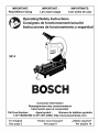 1
1
-
 2
2
-
 3
3
-
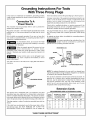 4
4
-
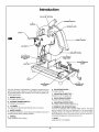 5
5
-
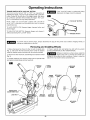 6
6
-
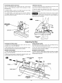 7
7
-
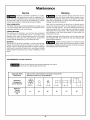 8
8
-
 9
9
-
 10
10
-
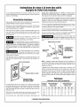 11
11
-
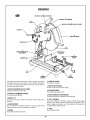 12
12
-
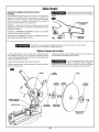 13
13
-
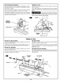 14
14
-
 15
15
-
 16
16
-
 17
17
-
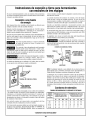 18
18
-
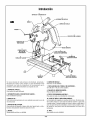 19
19
-
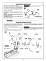 20
20
-
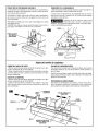 21
21
-
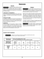 22
22
-
 23
23
-
 24
24


Bosch 3814 Le manuel du propriétaire
- Catégorie
- Outils électroportatifs
- Taper
- Le manuel du propriétaire
dans d''autres langues
- English: Bosch 3814 Owner's manual
- español: Bosch 3814 El manual del propietario