quiko SCARABEO Manuel utilisateur
- Catégorie
- Porte de garage
- Taper
- Manuel utilisateur

I
T
A
L
I
A
N
O
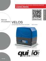
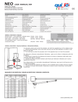
ARTICULATED ARM GEARMOTOR FOR SWING GATES
u
s
e
a
n
d
m
a
i
n
t
e
n
a
n
c
e
m
a
n
u
a
l
SCARABEO
E
N
G
L
I
S
H
V05/2020
NEW 2019 MODEL

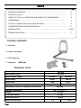
1- Operator
1- Fastening plates
1- Unlocking key
1- Capacitor (230Vca)
PACKING CONTENTS .............................................................................
2
TECHNICAL DATA ...................................................................................
2
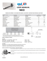
VIEW OF TYPICAL AUTOMATION AND NAMES OF COMPONENTS .............
3
DIMENSIONS .........................................................................................
3
TYPICAL CONNECTION AND CABLE SECTION ..........................................
4
CONSIDERATIONS FOR INSTALLATION ...................................................
4
INSTALLATION .......................................................................................
4-5-6
TROUBLESHOOTING ...............................................................................
7
PACKING CONTENTS
TECHNICAL DATA
Max. weight of gate
200 Kg
Max. width of gate
2,50 mt
Motors power supply
24 Vdc
230 Vac
Motor power
50 W
200 W
Motor RPM 100
1400
Condenser
/
10uF
Mechanical unlock for emergency manoeuvre With key
Working temperature
-30° C / +70° C
weight
9.5 Kg
Protection rating
IP 44
Opening time 90°
15 sec
Motor current input
3 A
1,2 A

2
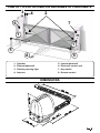
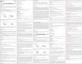
VIEW OF TYPICAL AUTOMATION AND NAMES OF COMPONENTS
4
1
1
6
7
5
8
5
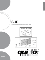
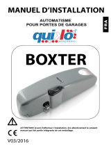
DIMENSIONS
3
1- Operator
2- External photocell
3- Flashing warning light
4- Antenna
5- Internal photocell
6- Electronic control unit
7- Key-switch
8- Remote control
180 mm
295 mm
254 mm
380 mm
420 mm

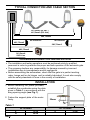
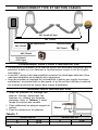
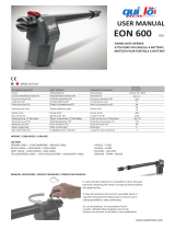
TYPICAL CONNECTION AND CABLE SECTION
2X1,5mm2 (24 Vdc )
4X1,5mm2 (230 Vca )
2X0,75mm2
4X0,75mm2
4X0,75mm2
2X0,75mm2
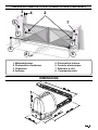
CONSIDERATIONS FOR INSTALLATION
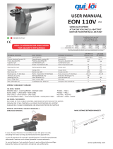
INSTALLATION
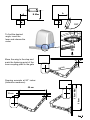
1. Before fastening the plates provided,
establish the coordinates using the data
given in Table 1 in accordance with the
wing opening angle (see Fig. 1).
2. Fasten the support plate of the motor
firmly. 20mm
A
90° OPENING
120° OPENING
A
13 cm
A
19 cm
B
30 cm
Table 1
RX Photocell TX Photocell
3X1,5mm2
230V Line
!
The installation and testing operations must be performed solely by qualified
personnel in order to guarantee the proper and safe operation of the automatic gate.
! The company declines any responsibility for damage caused by incorrect
installations due to incompetence and/or negligence.
! Before assembling the automatism, check that the gate is in perfect working
order, hangs well on its hinges and is suitably lubricated. It must also comply
with the safety standards in force in the country of installation.

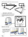
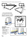
AA
B Max
120°
50 cm
30 cm Max
50 cm
15 cm
65 cm
To find the desired
angle, insert the
lever and release the
motor
Move the wing to the stop and
mark the fastening point of the
lever coupling plate to the gate
Opening example at 90° indoor
(indicative measures)

50 cm
ü Insert the supplied key in
the specific lock located
on the lever of the motor
ü Turn the key clockwise
üPull the lever up to
unlock
20 cm
50 cm
20 cm
To assemble the mechanical limit switches
for opening and closing, insert the cams in
the desired position and lock with the
screws.
MECHANICAL LIMIT SWITCH
Opening example over 90° indoor (indicative measures)
EMERGENCY RELEASE

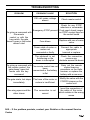
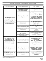
PROBLEM PROBABLE CAUSE SOLUTION
On giving a command with
the remote
control or with the
key-switch, the gate
doesn’t open or the motor
doesn’t start
230 volt mains voltage
absent Check master switch
Emergency STOP present
Check for any STOP
selectors or commands.
If not used, check jumper
on STOP contact input on
the control board
Fuse blown Replace with one of same
value.
Power cable of motor or
motors not
connected or faulty.
Connect the cable to
appropriate
terminal or replace.
The photocell is not
functioning or the
beam is interrupted
Check the connection,
remove any
obstacle across the beam
On giving a command with
the remote control, the
gate doesn’t open but
works with the key
command
The remote control has not
been
memorised or the battery
is flat
Carry out the remote
control learning
procedure on the radio
receiver or replace the
battery with a new one..
The gate starts, but stops
immediately
The force of the motor or
motors is insufficient
Modify the value with the
FORCE trimmer on the
control unit
One wing opens and the
other closes
The connection is not
correct
Invert the connection of
the cable of the motor
which rotates in the wrong
sense
N.B. - If the problem persists, contact your Retailer or the nearest Service
Centre
TROUBLESHOOTING

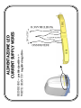
ALIMENTAZIONE LED
CURRENT SUPPLY WIRES
RED/ROSSO = positive/positivo +
WHITE BIANCO= negative/negativo-
RED/ROSSO
WHITE/BIANCO
RED/ROSSO
WHITE/BIANCO
+
-
24VAC/DC
LED1
LED2

MAINTENANCE
Actuators need very little maintenance; however their function depends also on the gate conditions,
hence here are operations to be done to keep the gate efficient at all times.
Warning: no one but the maintenance man, who must be a specialized technician, must be able to
control the automatic gate while it is being serviced. For this reason please turn off electricity,
avoiding also electric shocks hazard. If on the contrary electricity must be on for certain checks,
remember to check or disable any control device (remote controls, push button panels etc.) except
the one used by the service man.
Routine maintenance
Each of the following operations must be done when needed and in all cases at least every 6 months:
1) Mechanical maintenance
- Lubricate (with oilier) the hinges on which the gate swings;
- check the good conditions of brackets and motor’s hinges;
- do an unlocking operation to be sure the mechanism is always efficient.
2) Electrical maintenance
- Check the proper working of the safety devices;
- check the electronic friction’s efficacy;
- check the earth system’s (differential’s) efficacy. Try the differential switcher once a month
by pushing the special test button on the switcher.
GENERAL ADVICE
Install a gate’s safety system that complies with current regulations. Choose short routes for cables
and keep power cables separate from control ones. Install the control card in a waterproof box.
Please refer to current regulations when setting the gear motor’s maximum torque.
We advice you to install an outdoor switch, in compliance with European standards on the issue of
safety, to turn the electricity off when servicing the gate.
Check that each single installed device is efficient and effective.
Affix easily readable signs warning about the presence of a motorized gate.
USE
It is absolutely forbidden to use the device for any other purposes. The installed electronic unit (which
must have built-in electric friction), allows to select the following functions:
automatic: one control impulse will open or close the gate;
semi-automatic: one control impulse will open or close the gate.
In case of blackout, act on the manual unlocking device and move manually the gate. Remember that
this is an automatic device powered by electricity, consequently use with care. In particular,
remember:
- not to touch the device with wet hands and/or wet or bare feet;
- to turn off electricity before opening the control box and/or actuator;
- not to pull the lead to pull the plug out;
- to put the gate in movement only when it is completely visible;
- to keep out of the gate’s range of action if it is moving. Wait until it has stopped;
- not to let children or animals play near the gate;
- not to let children use the remote control or other operating devices;
- to carry out routine maintenance;
- in case of failure, to turn off electricity and operate the gate manually only if it is possible and
safe. Refrain from touching the gate and call an authorized technician.
www.quikoitaly.com

E
N
G
L
I
S
H
DECLARATION OF CONFORMITY
(OF THE MANUFACTURER)
Manufacturer: QUIKO ITALY SAS
hereby declares, under his liability, that the products:
QK-SCA24 , QK-SCA230
are in compliance with the essential safety requirements of the regulations:
Electromagnetic Compatibility Directive .........................2004/108/EC
Low Voltage Directive ......................................................2006/95/EC
Machinery Directive .........................................................2006/42/EC
and their amendments and modifications, and with the regulations set forth by the
National Legislative Body of the country in which the machinery is destined for use.
Via Seccalegno, 19
36040 Sossano (VI)
Italia
Managing Director
Luca Borinato
Sossano, 1/1/2018
www.quikoitaly.com

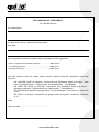
DECLARATION OF CONFORMITY
(OF THE INSTALLER)
The undersigned:
in charge of the set-up, declares that the product:
Gate type:
are in compliance with the essential safety requirements of the regulations:
Electro magnetic Compatibility Directive .........................2004/108/EC
Low Voltage Directive ............................................................2006/95/EC
Machinery Directive ................................................................2006/42/EC
and also declares that the related and/or specific national technical regulations have been
followed:
EN 12453/EN 12445 on Industrial, Commercial and Residential Gates and Doors – Safe
Use of Motorized Doors – Requirements and Classification – Test Methods;
EN 12604/ EN 12605 on Industrial, Commercial and Residential Gates and Doors –
Mechanical Aspects – Requirements and Classification – Test Methods;
CEI 64/8 Electrical Systems Using Nominal Tension Not Higher Than 1000V a.c. and 1500
V d.c.;
EN 13241-1 (Industrial, commercial and garage doors and gates), conformity evaluation
(6.3).
Notes:
Place and date: ………………………………………
www.quikoitaly.com

Quiko Italy
Via Seccalegno, 19
36040 Sossano (VI) - Italy
Tel. +39 0444 785513
Fax +39 0444 782371
info@quiko.biz
www.quikoitaly.com

I
T
A
L
I
A
N
O
Bras articulés pour portail battant
SCARABEO
F
R
A
V05/2020
Manuel d’installation

Poids maxi battant
Largeur maxi battant
Alimentation moteur
Puissance moteur
Régime moteur
Condenseur
Déblocage mécanique pour manœuvre
d’arrêt d’urgence
Température de fonctionnement
Poids réducteur de vitesse
Degré de protection
Temps mis pour ouverture à 90°
Courant absorbé moteur
Composition de l’emballage .................................................................
2
Caractéristiques techniques..................................................................
2
Tabbleau général ..................................................................................
3
Dimensions............................................................................................
3
Branchement et section câbles ............................................................
4
Considérations pour l’installations .......................................................
4
Modalités d’installation .........................................................................
4-5-6
Inconvénients: causea et solutions .....................................................
7
Suggestions et sécurités ......................................................................
8
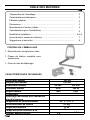
TABLE DES MATIÈRES
CONTENU DE L’EMBALLAGE
CARACTÉRISTIQUES TECHNIQUES
1- Motoréducteur complet avec bras
1- Plaque de fixation complète avec
accessoires
1- Paire de clés de déblocage
200 Kg
2,50 mt
24 Vdc
230 Vac
50 W
200 W
1400
10uF
-30° C / +70° C
9.5 Kg
IP 44
15 sec
3 A
1,2 A
1400

2
4
1
1
6
7
5
8
5
DIMENSIONS
3
180 mm
295 mm
254 mm
380 mm
420 mm
TABLEAU AUTOMATION TYPE ET NOMENCLATURE COMPOSANTS
1. Moteuréducteur
2. Photocellule d’extérieur
3. Clignotant
4. Antenne
5. Photocellule interne
6. Centrale électronique
7. Sélecteur à clef
8. Commande radio

2X1,5mm2 (24 Vdc )
2X0,75mm2
4X0,75mm2
4X0,75mm2
2X0,75mm2
20mm
A
OUVERTURE 90°
OUVERTURE 120°
A
13 cm
A
19 cm
B
30 cm
Tabella 1
BRANCHEMENT TYPE ET SECTION CÂBLES
RX photocellule TX photocellule
3X1,5mm2
230V Ligne
CONSIDÉRATIONS POUR L’INSTALLATION
·
Les opérations d’installation et de contrôle doivent être effectuées uniquement par du
personnel qualifié en vue d’assurer le fonctionnement correct et sûr de la grille
automatique.
·
La société , décline toute responsabilité concernant les dommages découlant d’une
mauvaise installation par incapacité et/ou négligence.
·
Avant de procéder au montage de l’automatisme, s’assurer que la grille fonctionne
parfaitement, en pivotant bien sur des gonds, et qu’elle est bien lubrifiée et conforme
aux normes de sécurité en vigueur dans le pays d’installation.
MODALITÉS D’INSTALLATION
1. Avant de procéder au montage des
plaques fournies, déterminez les
mesures en utilisant les données
indiquées dans le Tableau 1 selon
l'angle d'ouverture des vantails
2. Fixez solidement les plaques support du
moteur.
3. Fixez les moteurs sur les plaques.

AA
B Max
120°
50 cm
30 cm Max
50 cm
15 cm
65 cm
Pour trouver l'angle
désiré, le insérez le
levier et déverrouillez
moteur
Menez le vantail jusqu'à la
butée et marquez le point de
fixation de la plaque support
levier au portailo
Exemple d'ouverture 90° à l'intérieur
(mesures indicatives)

50 cm
Ÿ Insérez la clé fournie
dans la serrure
spécifique situé sur le
levier du moteur
Ÿ Tournez la clé dans le
sens horaire
Ÿ Tirez le levier jusqu'au
déverrouillage
20 cm
50 cm
20 cm
Pour assembler les fins de course
mécaniques d'ouverture et fermeture,
insérez les cames dans la position
souhaitée et verrouillez avec les vis.
FIN DE COURSE MÉCANIQUE
Exemple d'ouverture plus de 90° à l'intérieur (mesures indicatives)
PROCÉDURE
DÉVERROUILLAGE DE
SECOURS

INCONVÉNIENTS – CAUSES ET SOLUTIONS
INCONVÉNIENT CAUSE PROBABLE SOLUTION
En présence d’une
commande avec la
commande radio ou avec
le sélecteur, la grille ne
s’ouvre pas et les moteurs
ne démarrent pas.
Alimentation secteur
230 volts absente
Contrôler l’interrupteur
principal
Présence d’un arrêt
d’urgence
Contrôler les commandes
éventuelles ou les
commandes de STOP.
S’ils ne sont pas utilisés,
contrôler le jumper sur
entrée contact STOP sur
la centrale
Fusible brûlé
Le remplacer par un
fusible de la
même valeur.
Câble d’alimentation des
moteurs non branché ou
défectueux.
Brancher les câbles dans
les
bornes prévue à cet effet
ou les
remplacer.
Il y a un obstacle au milieu
de la cellule
photoélectrique ou elle ne
fonctionne pas
Contrôler le branchement,
enlever
l’obstacle éventuel.
En présence d’une
commande de la
commande radio, ne
s’ouvre pas, mais
fonctionne avec la
commande à clef
La commande radio n’a
pas été mémorisée ou la
batterie est déchargée
Exécuter la procédure de
reconnaissance de la
commande
radio sur le récepteur
radio ou
remplacer la batterie par
une
batterie neuve..
La grille démarre, mais
s’arrête
La force des moteurs est
insuffisante
Modifier la valeur avec le
potentiomètre FORCE
situé sur la centrale
Un battant s’ouvre et
l’autre se ferme
Le branchement n’est pas
correct
Inverser la polarité des
câbles du moteur
concerné
Nota: - Si l’inconvénient persiste, contacter le revendeur ou le centre de service
après-vente le plus proche

ALIMENTAZIONE LED
CURRENT SUPPLY WIRES
RED/ROSSO = positive/positivo +
WHITE BIANCO= negative/negativo-
RED/ROSSO
WHITE/BIANCO
RED/ROSSO
WHITE/BIANCO
+
-
24VAC/DC
LED1
LED2
La page est en cours de chargement...
La page est en cours de chargement...
La page est en cours de chargement...
La page est en cours de chargement...
-
 1
1
-
 2
2
-
 3
3
-
 4
4
-
 5
5
-
 6
6
-
 7
7
-
 8
8
-
 9
9
-
 10
10
-
 11
11
-
 12
12
-
 13
13
-
 14
14
-
 15
15
-
 16
16
-
 17
17
-
 18
18
-
 19
19
-
 20
20
-
 21
21
-
 22
22
-
 23
23
-
 24
24


quiko SCARABEO Manuel utilisateur
- Catégorie
- Porte de garage
- Taper
- Manuel utilisateur
dans d''autres langues
- English: quiko SCARABEO User manual
Documents connexes
-
 quiko Velos Manuel utilisateur
-
 quiko Velos Manuel utilisateur
-
 quiko Neo Manuel utilisateur
-
 quiko Sub Manuel utilisateur
-
 quiko QK-CE24A Manuel utilisateur
-
 quiko EON110 Manuel utilisateur
-
 quiko Neo Manuel utilisateur
-
 quiko QK-LIBWIFI Manuel utilisateur
-
 quiko BOXTER+CE220BASC Manuel utilisateur
-
 quiko EON600 Manuel utilisateur


