Hikoki C 7SB2 Manuel utilisateur
- Catégorie
- Outils électroportatifs
- Taper
- Manuel utilisateur
Ce manuel convient également à

Model
Circular saw
Modèle
Scie circulaire
Modelo
Sierra circular
C 7SB2
DOUBLE INSULATION
DOUBLE ISOLATION
AISLAMIENTO DOBLE
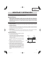
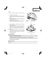
INSTRUCTIONS DE SECURITE ET MODE D’EMPLOI
AVERTISSEMENT
Une utilisation INCORRECTE OU DANGEREUSE de cet outil motorisé peut entraîner la
mort ou de sérieuses blessures corporelles!
Ce mode d’emploi contient d’importantes informations à propos de la sécurité de ce produit.
Prière de lire et de comprendre ce mode d’emploi AVANT d’utiliser l’outil motorisé. Garder ce
mode d’emploi à la disponibilité des autres utilisateurs et propriétaires avant qu’ils utilisent
l’outil motorisé. Ce mode d’emploi doit être conservé dans un endroit sûr.
SAFETY INSTRUCTIONS AND INSTRUCTION MANUAL
WARNING
IMPROPER OR UNSAFE use of this power tool can result in death or serious bodily injury!
This manual contains important information about product safety. Please read and
understand this manual BEFORE operating the power tool. Please keep this manual
available for other users and owners before they use the power tool. This manual should be
stored in safe place.
INSTRUCCIONES DE SEGURIDAD Y MANUAL DE INSTRUCCIONES
ADVERTENCIA
¡La utilización INAPROPIADA O PELIGROSA de esta herramienta eléctrica puede resultar
en lesiones de gravedad o la muerte!
Este manual contiene información importante sobre la seguridad del producto. Lea y com-
prenda este manual ANTES de utilizar la herramienta eléctrica. Guarde este manual para
que puedan leerlo otras personas antes de utilizar la herramienta eléctrica. Este manual
debe ser guardado en un lugar seguro.

2
CONTENTS
TABLE DES MATIERES
ÍNDICE
Página
ESPECIFICACIONES ............................................38
MONTAJE Y OPERACIÓN ........................................39
APLICACIONES ....................................................39
ANTES DE LA OPERACIÓN ..................................39
AJUSTE DE LA SIERRA ANTES DE
UTILIZARLA ....................................................40
PROCEDIMIENTOS DE CORTE ...........................42
MONTAJE Y DESMONTAJE DE LA
CUCHILLA DE LA SIERRA .............................43
MANTENIMIENTO E INSPECCIÓN .........................44
ACCESORIOS ...........................................................46
ACCESORIOS ESTÁNDAR ...................................46
ACCESORIOS OPCIONALES ...............................46
LISTA DE PIEZAS .....................................................47
Français
Español
English
Page
IMPORTANT SAFETY INFORMATION .................. 3
MEANINGS OF SIGNAL WORDS ......................... 3
MEANINGS OF SYMBOLS ................................... 3
SAFETY ..................................................................... 3
GENERAL POWER TOOL SAFETY
WARNINGS ......................................................3
CIRCULAR SAW SAFETY WARNINGS ...................4
SPECIFIC SAFETY RULES AND SYMBOLS ......... 6
DOUBLE INSULATION FOR SAFER
OPERATION .....................................................7
FUNCTIONAL DESCRIPTION ....................................8
NAME OF PARTS ....................................................8
SPECIFICATIONS ...................................................8
Page
ASSEMBLY AND OPERATION ...................................9
APPLICATIONS .......................................................9
PRIOR TO OPERATION ..........................................9
ADJUSTING THE SAW PRIOR TO USE ................10
CUTTING PROCEDURES .....................................12
MOUNTING AND DISMOUNTING THE
SAW BLADE ..................................................13
MAINTENANCE AND INSPECTION ........................14
ACCESSORIES .........................................................16
STANDARD ACCESSORIES .................................16
OPTIONAL ACCESSORIES ...................................16
PARTS LIST ..............................................................47
Page
SPECIFICATIONS .................................................23
ASSEMBLAGE ET FONCTIONNEMENT .................24
APPLICATIONS .....................................................24
AVANT L’UTILISATION ...........................................24
RÉGLAGE DE LA SCIE AVANT
L’UTILISATION ................................................25
PROCEDURES DE COUPE ...................................27
MONTAGE ET DÉMONTAGE DE LA LAME
DE SCIE ..........................................................28
ENTRETIEN ET INSPECTION ..................................29
ACCESOIRES ...........................................................31
ACCESSOIRES STANDARD .................................31
ACCESSOIRES EN OPTION .................................31
LISTE DES PIECES ..................................................47
Página
INFORMACIÓN IMPORTANTE SOBRE
SEGURIDAD ...................................................32
SIGNIFICADO DE LAS PALABRAS DE
SEÑALIZACIÓN .............................................32
SIGNIFICADO DE SÍMBOLOS ..............................32
SEGURIDAD .............................................................32
ADVERTENCIAS DE SEGURIDAD GENERAL
DE LA HERRAMIENTA ELÉCTRICA ..............32
ADVERTENCIAS DE SEGURIDAD DE LA
SIERRA CIRCULAR ........................................34
NORMAS Y SÍMBOLOS ESPECÍFICOS DE
SEGURIDAD ..................................................35
AISLAMIENTO DOBLE PARA OFRECER UNA
OPERACIÓN MÁS SEGURA ..........................37
DESCRIPCIÓN FUNCIONAL ...................................38
NOMENCLATURA .................................................38
Page
INFORMATIONS IMPORTANTES
DE SÉCURITÉ ................................................17
SIGNIFICATION DES MOTS
D’AVERTISSEMENT .......................................17
SIGNIFICATION DES SYMBOLES .........................17
SECURITE .................................................................17
AVERTISSEMENTS DE SÉCURITÉ GÉNÉRAUX
CONCERNANT LES OUTILS ÉLECTRIQUES
...17
AVERTISSEMENTS DE SÉCURITÉ RELATIFS
À LA SCIE CIRCULAIRE .................................19
RÈGLES DE SÉCURITÉ SPÉCIFIQUES ET
SYMBOLES ....................................................20
DOUBLE ISOLATION POUR UN
FONCTIONNEMENT PLUS SUR ....................22
DESCRIPTION FONCTIONNELLE ...........................23
NOM DES PARTIES ..............................................23

English
3
1) Work area safety
a) Keep work area clean and well lit.
Cluttered or dark areas invite accidents.
b) Do not operate power tools in explosive
atmospheres, such as in the presence of
fl ammable liquids, gases or dust.
Power tools create sparks which may ignite the
dust or fumes.
c) Keep children and bystanders away while
operating a power tool.
Distractions can cause you to lose control.
2) Electrical safety
a) Power tool plugs must match the outlet.
Never modify the plug in any way.
Do not use any adapter plugs with earthed
(grounded) power tools.
Unmodified plugs and matching outlets will
reduce risk of electric shock.
b) Avoid body contact with earthed or grounded
surfaces such as pipes, radiators, ranges and
refrigerators.
There is an increased risk of electric shock if
your body is earthed or grounded.
IMPORTANT SAFETY INFORMATION
Read and understand all of the safety precautions, warnings and operating instructions in the Instruction Manual before
operating or maintaining this power tool.
Most accidents that result from power tool operation and maintenance are caused by the failure to observe basic safety
rules or precautions. An accident can often be avoided by recognizing a potentially hazardous situation before it occurs,
and by observing appropriate safety procedures.
Basic safety precautions are outlined in the “SAFETY” section of this Instruction Manual and in the sections which contain
the operation and maintenance instructions.
Hazards that must be avoided to prevent bodily injury or machine damage are identifi ed by WARNINGS on the power tool
and in this Instruction Manual.
NEVER use this power tool in a manner that has not been specifi cally recommended by HITACHI.
MEANINGS OF SIGNAL WORDS
WARNING indicates a potentially hazardous situations which, if ignored, could result in death or serious injury.
CAUTION indicates a potentially hazardous situations which, if not avoided, may result in minor or moderate injury, or
may cause machine damage.
NOTE emphasizes essential information.
MEANINGS OF SYMBOLS
SAFETY
GENERAL POWER TOOL SAFETY WARNINGS
WARNING:
Read all safety warnings and all instructions.
Failure to follow the warnings and instructions may result in electric shock, fi re and/or serious injury.
Save all warnings and instructions for future reference.
The term “power tool” in the warnings refers to your mains-operated (corded) power tool or battery-operated
(cordless) power tool.
Symbols
WARNING
The following show symbols used for the machine. Be sure that you understand their meaning before use.
Read all safety warnings and all instructions.
Failure to follow the warnings and instructions
may result in electric shock, fi re and/or serious
injury.
Always wear eye protection.
Always wear hearing protection.

English
4
c) Do not expose power tools to rain or wet
conditions.
Water entering a power tool will increase the
risk of electric shock.
d) Do not abuse the cord. Never use the cord
for carrying, pulling or unplugging the
power tool.
Keep cord away from heat, oil, sharp edges
or moving parts.
Damaged or entangled cords increase the risk
of electric shock.
e) When operating a power tool outdoors, use
an extension cord suitable for outdoor use.
Use of a cord suitable for outdoor use reduces
the risk of electric shock.
f) If operating a power tool in a damp location
is unavoidable, use a residual current device
(RCD) protected supply.
Use of an RCD reduces the risk of electric shock.
3) Personal safety
a) Stay alert, watch what you are doing and use
common sense when operating a power tool.
Do not use a power tool while you are tired
or under the influence of drugs, alcohol or
medication.
A moment of inattention while operating power
tools may result in serious personal injury.
b) Use personal protective equipment. Always
wear eye protection.
Protective equipment such as dust mask,
non-skid safety shoes, hard hat, or hearing
protection used for appropriate conditions will
reduce personal injuries.
c) Prevent unintentional starting. Ensure the
switch is in the off -position before connecting
to power source and/or battery pack, picking
up or carrying the tool.
Carrying power tools with your finger on the
switch or energising power tools that have the
switch on invites accidents.
d) Remove any adjusting key or wrench before
turning the power tool on.
A wrench or a key left attached to a rotating part of
the power tool may result in personal injury.
e) Do not overreach. Keep proper footing and
balance at all times.
This enables better control of the power tool in
unexpected situations.
f) Dress properly. Do not wear loose clothing
or jewellery. Keep your hair, clothing and
gloves away from moving parts.
Loose clothes, jewellery or long hair can be
caught in moving parts.
g) If devices are provided for the connection of
dust extraction and collection facilities, ensure
these are connected and properly used.
Use of dust collection can reduce dust-related
hazards.
4) Power tool use and care
a) Do not force the power tool. Use the correct
power tool for your application.
The correct power tool will do the job better and
safer at the rate for which it was designed.
b) Do not use the power tool if the switch does
not turn it on and off .
Any power tool that cannot be controlled with
the switch is dangerous and must be repaired.
c) Disconnect the plug from the power source
and/or the battery pack from the power tool
before making any adjustments, changing
accessories, or storing power tools.
Such preventive safety measures reduce the
risk of starting the power tool accidentally.
d) Store idle power tools out of the reach of
children and do not allow persons unfamiliar
with the power tool or these instructions to
operate the power tool.
Power tools are dangerous in the hands of
untrained users.
e) Maintain power tools. Check for misalignment
or binding of moving parts, breakage of parts
and any other condition that may aff ect the
power tool’s operation.
If damaged, have the power tool repaired
before use.
Many accidents are caused by poorly
maintained power tools.
f) Keep cutting tools sharp and clean.
Properly maintained cutting tools with sharp
cutting edges are less likely to bind and are
easier to control.
g) Use the power tool, accessories and tool bits
etc. in accordance with these instructions,
taking into account the working conditions
and the work to be performed.
Use of the power tool for operations different
from those intended could result in a hazardous
situation.
5) Service
a) Have your power tool serviced by a qualifi ed
repair person using only identical replacement
parts.
This will ensure that the safety of the power tool
is maintained.
CIRCULAR SAW SAFETY WARNINGS
Cutting procedures
a) DANGER: Keep hands away from cutting
area and the blade. Keep your second hand
on auxiliary handle, or motor housing.
If both hands are holding the saw, they cannot be
cut by the blade.
b) Do not reach underneath the workpiece.
The guard cannot protect you from the blade
below the workpiece.
c) Adjust the cutting depth to the thickness of
the workpiece.

English
5
Less than a full tooth of the blade teeth should be
visible below the workpiece.
d) Never hold piece being cut in your hands or
across your leg. Secure the workpiece to a stable
platform.
It is important to support the work properly to
minimize body exposure, blade binding, or loss of
control.
e) Hold the power tool by insulated gripping surfaces
only, when performing an operation where the
cutting tool may contact hidden wiring or its own
cord.
Contact with a “live” wire will also make exposed
metal parts of the power tool “live” and could give
the operator an electric shock.
f) When ripping always use a rip fence or straight
edge guide.
This improves the accuracy of cut and reduces the
chance of blade binding.
g) Always use blades with correct size and shape
(diamond versus round) of arbour holes.
Blades that do not match the mounting hardware of
the saw will run eccentrically, causing loss of control.
h) Never use damaged or incorrect blade washers
or bolt.
The blade washers and bolt were specially designed
for your saw, for optimum performance and safety
of operation.
Kickback causes and related warnings
– kickback is a sudden reaction to a pinched, bound
or misaligned saw blade, causing an uncontrolled
saw to lift up and out of the workpiece toward the
operator;
– when the blade is pinched or bound tightly by the
kerf closing down, the blade stalls and the motor
reaction drives the unit rapidly back toward the
operator;
– if the blade becomes twisted or misaligned in the
cut, the teeth at the back edge of the blade can dig
into the top surface of the wood causing the blade
to climb out of the kerf and jump back toward the
operator.
Kickback is the result of saw misuse and/or incorrect
operating procedures or conditions and can be avoided
by taking proper precautions as given below.
a) Maintain a fi rm grip with both hands on the saw
and position your arms to resist kickback forces.
Position your body to either side of the blade,
but not in line with the blade.
Kickback could cause the saw to jump backwards,
but kickback forces can be controlled by the
operator, if proper precautions are taken.
b) When blade is binding, or when interrupting a
cut for any reason, release the trigger and hold
the saw motionless in the material until the blade
comes to a complete stop.
Never attempt to remove the saw from the work
or pull the saw backward while the blade is in
motion or kickback may occur.
Investigate and take corrective actions to eliminate
the cause of blade binding.
c) When restarting a saw in the workpiece, centre
the saw blade in the kerf and check that saw
teeth are not engaged into the material.
If saw blade is binding, it may walk up or kickback
from the workpiece as the saw is restarted.
d) Support large panels to minimise the risk of
blade pinching and kickback.
Large panels tend to sag under their own weight.
Supports must be placed under the panel on both
sides, near the line of cut and near the edge of
the panel.
e) Do not use dull or damaged blades.
Unsharpened or improperly set blades produce
narrow kerf causing excessive friction, blade
binding and kickback.
f) Blade depth and bevel adjusting locking levers
must be tight and secure before making cut.
If blade adjustment shifts while cutting, it may
cause binding and kickback.
g) Use extra caution when sawing into existing
walls or other blind areas.
The protruding blade may cut objects that can
cause kickback.
Lower guard function
a) Check lower guard for proper closing before
each use. Do not operate the saw if lower
guard does not move freely and close instantly.
Never clamp or tie the lower guard into the
open position.
If saw is accidentally dropped, lower guard may be
bent.
Raise the lower guard with the retracting handle
and make sure it moves freely and does not touch
the blade or any other part, in all angles and
depths of cut.
b) Check the operation of the lower guard spring.
If the guard and the spring are not operating
properly, they must be serviced before use.
Lower guard may operate sluggishly due to
damaged parts, gummy deposits, or a build-up of
debris.
c) Lower guard should be retracted manually
only for special cuts such as “plunge cuts”
and “compound cuts”.
Raise lower guard by retracting handle and as
soon as blade enters the material, the lower guard
must be released.
For all other sawing, the lower guard should
operate automatically.
d) Always observe that the lower guard is covering
the blade before placing saw down on bench or
fl oor.
An unprotected, coasting blade will cause the saw
to walk backwards, cutting whatever is in its path.
Be aware of the time it takes for the blade to stop
after switch is released.

English
6
SPECIFIC SAFETY RULES AND SYMBOLS
1. Adjustments. Before cutting be sure depth and
bevel adjustments are tight.
2. Avoid cutting nails. Inspect for and remove all
nails from work piece before cutting.
3. When operating the saw, keep the cord away
from the cutting area and position it so that it
will not be caught on the workpiece during the
cutting operation.
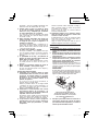
Operate with proper hand support, proper workpiece
support, and supply cord routing away from the work
area.
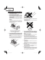
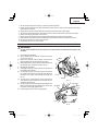
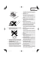
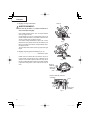
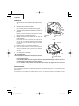
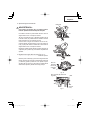
WARNING:
It is important to support the work piece properly and
to hold the saw fi rmly to prevent loss of control which
could cause personal injury. Fig. 1 illustrates typical
hand support of the saw.
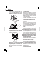
4. Place the wider portion of the saw base on that
part of the work piece which is solidly supported,
not on the section that will fall off when the cut is
made.
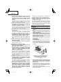
As examples, Fig. 2 illustrates the RIGHT way to cut
off the end of board, and Fig. 3 the WRONG way. If
the work piece is short or small, clamp it down.
DON’T TRY TO HOLD SHORT PLACES BY HAND!
5. Never attempt to saw with the circular saw held
upside down in a vise.
This is extremely dangerous and can lead to serious
accidents. (Fig. 4)
6. Before setting the tool down after completing a
cut, be sure that the lower (telescoping) guard
has closed and the blade has come to a complete
stop.
7. Never touch moving parts.
Never place your hands, fi ngers or other body parts
near the tool’s moving parts.
8. Never operate without all guards in place.
Never operate this tool without all guards or safety
features in place and in proper working order. If
maintenance or servicing requires the removal of a
guard or safety feature, be sure to replace the guard
or safety feature before resuming operation of the
tool.
9. Use right tool.
Don’t force small tool or attachment to do the job of a
heavy-duty tool.
Don’t use tool for purpose not intended —for
example— don’t use circular saw for cutting tree
limbs or logs.
10. Never use a power tool for applications other
than those specifi ed.
Never use a power tool for applications other than
those specifi ed in the Instruction Manual.
11. Handle tool correctly.
Operate the tool according to the instructions provided
herein. Do not drop or throw the tool. Never allow the
tool to be operated by children, individuals unfamiliar
with its operation or unauthorized personnel.
A TYPICAL ILLUSTRATION OF PROPER
HAND SUPPORT WORKPIECE SUPPORT,
AND SUPPLY CORD ROUTING.
Fig. 1
Fig. 2
Fig. 3
Fig. 4

English
7
12. Keep motor air vent clean.
The tool’s motor air vent must be kept clean so that
air can freely fl ow at all times. Check for dust build-up
frequently.
13. Operate power tools at the rated voltage.
Operate the power tool at voltages specifi ed on their
nameplates.
If using the power tool at a higher voltage than the
rated voltage, it will result in abnormally fast motor
revolution and may damage the unit and burn out the
motor.
14. Do not run the saw while carrying it at your side.
15. Keep all screws, bolts and covers tightly in
place.
Keep all screws, bolts, and plates tightly mounted.
Check their condition periodically.
16. Do not use power tools if the plastic housing or
handle is cracked.
Cracks in the tool’s housing or handle can lead to
electric shock. Such tools should not be used until
repaired.
17. Blades and accessories must be securely mounted
to the tool.
Prevent potential injuries to yourself or others.
Blades, cutting implements and accessories which
have been mounted to the tool should be secure and
tight.
18. Never use a tool which is defective or operating
abnormally.
If the tool appears to be operating unusually, making
strange noises, or otherwise appears defective, stop
using it immediately and arrange for repairs by a
Hitachi authorized service center.
19. Carefully handle power tools.
Should a power tool be dropped or struck against
hard materials inadvertently, it may be deformed,
cracked, or damaged.
20. Do not wipe plastic parts with solvent.
Solvents such as gasoline, thinner benzine, carbon
tetrachloride, and alcohol may damage and crack
plastic parts. Do not wipe them with such solvents.
Wipe plastic parts with a soft cloth lightly dampened
with soapy water and dried thoroughly.
21. Never wear gloves made of material liable to roll
up such as cotton, wool, cloth or string, etc.
22. Defi nitions for symbols.
V ............. volts
Hz ........... hertz
A ............. amperes
n
o
.......... no load speed
.......... Class II Construction
---/min ..... revolutions per minute
........... alternating or direct current
DOUBLE INSULATION FOR SAFER
OPERATION
To ensure safer operation of this power tool, HITACHI has
adopted a double insulation design. “Double insulation”
means that two physically separated insulation systems
have been used to insulate the electrically conductive
materials connected to the power supply from the outer
frame handled by the operator. Therefore, either the symbol
“ ” or the words “Double insulation” appear on the
power tool or on the nameplate.
Although this system has no external grounding, you must
still follow the normal electrical safety precautions given in
this Instruction Manual, including not using the power tool
in wet environments.
To keep the double insulation system effective, follow
these precautions:
Only HITACHI AUTHORIZED SERVICE CENTER
should disassemble or assemble this power tool, and
only genuine HITACHI replacement parts should be
installed.
Clean the exterior of the power tool only with a soft
cloth moistened with soapy water, and dry thoroughly.
Never use solvents, gasoline or thinners on plastic
components; otherwise the plastic may dissolve.
SAVE THESE INSTRUCTIONS
AND
MAKE THEM AVAILABLE TO OTHER USERS
AND
OWNERS OF THIS TOOL!

English
8
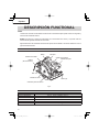
FUNCTIONAL DESCRIPTION
NOTE:
The information contained in this Instruction Manual is designed to assist you in the safe operation and maintenance
of the power tool.
NEVER operate, or attempt any maintenance on the tool unless you have first read and understood all safety
instructions contained in this manual.
Some illustrations in this Instruction Manual may show details or attachments that diff er from those on your own
power tool.
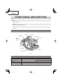
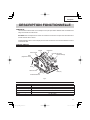
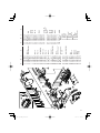
NAME OF PARTS
SPECIFICATIONS
Fig. 5
Handle Switch
Gear Cover
Lock Lever
Lever (A)
Lower Guard
Saw Blade
Base
Lever
(Retracting
Handle)
Blade Cover
Motor Single-Phase, Series Commutator Motor
Power Source Single-Phase 120 V AC 60 Hz, 120 V DC
Max. Cutting Depth 2-3/8" (60 mm)
Current 15 A
No-Load Speed 5800/min.
Weight (without cord) 10.1 lbs (4.6 kg)

English
9
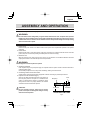
ASSEMBLY AND OPERATION
APPLICATIONS
The tool is designed for wood cutting applications.
WARNING:
Use extra caution when cutting freshly cut green lumber, hardwood, wet wood, composite wood, pressure
treated wood, wood containing knots or having other characteristics which may put a heavy load on the saw
or blade. If this occurs, do not force the tool. Push the tool more slowly, but with enough force to keep working
without much decrease in speed.
PRIOR TO OPERATION
1. Power source
Ensure that the power source to be utilized conforms to the power source requirements specifi ed on the product
nameplate.
2. Power switch
Ensure that the switch is in the OFF position. If the plug is connected to a receptacle while the switch is in the ON
position, the power tool will start operating immediately and can cause serious injury.
3. Extension cord
When the work area is far away from the power source, use an extension cord of suffi cient thickness and rated
capacity. The extension cord should be kept as short as practicable.
WARNING:
Damaged cord must be replaced or repaired.
4. Check the receptacle
If the receptacle only loosely accepts the plug, the receptacle must be repaired. Contact a licensed electrician to
make appropriate repairs.
If such a faulty receptacle is used, it may cause overheating, resulting in a serious hazard.
5. Confi rming condition of the environment:
Confi rm that the work site is placed under appropriate conditions conforming to prescribed precautions.
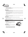
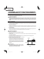
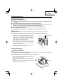
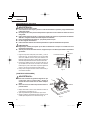
6. Prepare a wooden workbench (Fig. 6)
Since the saw blade will extend beyond the lower surface of
the work piece, place the work piece on a workbench when
cutting. If a square block is utilized as a workbench, select
level ground to ensure it is properly stabilized. An unstable
workbench will result in hazardous operation.
CAUTION:
To avoid possible accident, always ensure that the
portion of work piece remaining after cutting is securely
anchored or held in position.
Work piece
Base
Saw Blade
Fig. 6
Workbench

English
10
7. Check if lever (A)s are tightened.
If the lever (A) to adjust cutting depth (Fig. 7) and lever (A) to adjust angle of inclination (Fig. 8) are loose, injury can
result. Make sure that they are tightened securely.
8. Check performance of safety cover
WARNING:
Make absolutely sure that the safety cover is not fi xed. Also, check and see if it can move smoothly. If the
saw blade is kept exposed injury can result.
The lower guard (refer to Fig. 5) serves to protect your body from coming into contact with the saw blade. Make
absolutely certain that the cover smoothly performs to cover the saw blade. If the safety cover should not move
smoothly, never use it without repairing it.
In such a case, get in touch with the store where you bought the circular saw or the HITACHI Authorized Service
Center for necessary repair.
9. Eye protection
Always wear eye protection with side shields that meets the requirements of ANSI Standard Z87.1. Ordinary
eyeglasses do not provide adequate protection.
WARNING:
Operating the tool without wearing proper eye protection may result in serious injury.
10. Check if saw blade is tightened
Refer to [mounting and dismounting the saw blade] in Page 13, and make sure that the fl ange bolt is tightened
securely.
ADJUSTSING THE SAW PRIOR TO USE
WARNING:
To avoid serious accidents, ensure the switch is in OFF
position, and disconnect the plug from the receptacle.
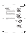
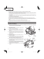
1. Adjusting the cutting depth (Fig. 7)
WARNING:
If the lever (A) is loose, injury can result. Tighten it
securely after adjustment.
To adjust cutting depth, loosen the lever (A) and, while
holding the base with one hand, move the main body up and
down to obtain the prescribed cutting depth. After adjusting
to the prescribed cutting depth, tighten the lever (A) securely.
Lever (A)
Loosen
Link
Base
Fig. 7
Tighten

English
11
2. Adjusting the angle of inclination
WARNING:
If the lever (A) is loose, injury can result. Tighten it
securely after adjustment.
You can incline saw blade from 0˚ to a maximum angle of 55˚
in relation to the base.
As shown in Fig. 8 by loosing the lever (A) on the bevel scale,
the saw blade may be inclined to an angle of 45˚ in relation to
the base.
If you use inclination angle of over 45˚, as shown in Fig. 9
move the lever (A) to inside, the saw blade may be inclined to
a maximum angle of 55˚ in relation to the base.
Always ensure that the lever (A) is thoroughly tightened after
making the desired adjustment.
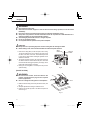
3. Regulating the guide (Rip fence) (Fig. 10, 11)
................................................................Optional Accessory
Install the wing bolt (B) and lock spring on the base. Insert
the guide into the base, move it left and right and adjust the
cutting position. Tighten the wing bolt (B) and fi x the guide.
The guide can be installed either from the left or the right side
of the main body.
Fig. 8
0˚ – 45˚
Lever (A)
Fig. 9
45˚ – 55˚
Fig. 10
Base
Wing Bolt (B)
Lock
Spring
Wing Bolt (B), Lock Spring
Base
Fig. 11
Guide
(Rip Fence)

English
12
CUTTING PROCEDURES
WARNING:
●
Never touch the moving parts.
●
Should the saw blade be stopped or make an abnormal noise during operation, turn off the switch
immediately.
●
Don't remove circular saw from work piece during a cut while the saw blade is moving.
●
Always wear eye protection with side shields that meets the requirements of ANSI Standard Z87.1.
Ordinary eyeglasses do not provide adequate protection.
●
Avoid cutting any material like metal, etc., that give off sparks.
●
Do not use any abrasive wheels.
●
Use only blade diameter specifi ed on the product nameplate.
CAUTION:
●
Always take care in preventing the power cord from coming near the revolving saw blade.
●
Before starting to saw, ensure that the saw blade has reached full speed revolution.
1. Place the saw body (base) on the work piece, and as in Fig.
12 align the intended line of cut with the saw blade, using
the notch at the front of the base. This relationship of base
to work pieces should remain unchanged regardless of the
inclination of the base.
2. The switch should be turned to the ON position before the
saw blade comes into contact with the work piece. The switch
is turned ON when the trigger is pulled by one’s fi nger, and is
turned OFF when the trigger is released.
3. Moving the saw straight at a constant speed will produce
optimum cutting.
[POCKET CUTTING]
WARNING:
●
To avoid serious accident, ensure the switch is OFF
position, and disconnect the plug from the receptacle
before any adjustment.
●
Never tie or wedge the lower guard in a raised position.
1. Mark the desired cutting area clearly with lines all side. (See
Fig. 13)
2. Set depth adjustment according to material to be cut.
3. Push the lever all the way back so the blade is exposed as
shown in Fig. 13.
Fig. 12
When not
Inclined
When
Inclined 45°
Fig. 13
Lever

English
13
4. Tilt saw forward and align the notch (Fig. 12) with the pre-marked guide line.
5. Release the lever. When the lower guard contacts the work piece surface, it will be in proper position to open freely
when cutting is commenced.
6. Holding the saw in position, with the blade not contacting the work piece surface, pull the trigger.
7. After the saw has reached full speed, gradually lower rear end of the saw until its base rests on the work surface.
8. Advance saw along the cutting line up to the corner.
9. Release trigger and allow blade to stop completely before withdrawing the blade from the work piece.
Never under any circumstances pull the saw backwards while the blade is in motion, as kickback may result.
10. Use a jig saw or hand saw to cut the corners out clean.
11. When starting each new cut, repeat as above.
MOUNTING AND DISMOUNTING THE SAW BLADE
WARNING:
To avoid serious accident ensure the switch is in the OFF position, and disconnect the plug from the
receptacle.
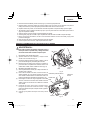
1. Dismounting the saw blade
(1) Set the cutting volume at maximum, and place the Circular
Saw as shown in Fig. 14.
(2) Depress the lock lever, lock the spindle, and remove the
hexagonal-fl ange bolt and washer (B) with the wrench.
(3) While holding the lever to keep the lower guard fully retracted
into the blade cover, remove the saw blade. (Fig. 15)
2. Mounting the saw blade
(1) Thoroughly remove any sawdust which has accumulated on
the spindle, bolt and washers.
(2) For mounting saw blade, the concave sides of both washers
(A) and (B) must be fi tted to the saw blade sides. Mount the
saw blade on the spindle, and fi nally affi x washer (B) (See
Fig. 16)
(3) To assure proper rotation direction of the saw blade, the
arrow direction on the saw blade must coincide with the arrow
direction on the blade cover.
(4) Using the fi ngers, tighten the hexagonal bolt retaining the saw
blade as much as possible. Then depress the lock lever, lock
the spindle, and thoroughly tighten the bolt.
(5) Confi rm that the lock lever is in the original position.
Fig. 14
Lock Lever
Wrench
Loosen
Tighten
Fig. 15
Saw Blade
Lower Guard
Blade
Cover
Lever

English
14
Hexagonal
Flange Bolt
Washer (A)
Washer (B)
Saw Blade
Fig. 16
MAINTENANCE AND INSPECTION
WARNING:
To avoid serious accident, ensure the switch is in the OFF position and disconnect the plug from the
receptacle during maintenance and inspection.
1. Inspecting the saw blade:
Since use of a dull saw blade will degrade effi ciency and cause possible motor malfunction, sharpen or replace the
saw blade as soon as abrasion is noted.
CAUTION:
If a dull saw blade is used, reactive force is increased during cutting operation. Avoid the use of the dull
saw blade without repair.
2. Check the screws
Loose screws are dangerous. Regularly inspect them and make sure they are tight.
CAUTION:
Using this power tool with loosened screws is extremely dangerous.
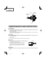
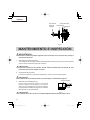
3 . Inspecting the carbon brushes (Fig. 17)
The motor employs carbon brushes which are consumable
parts. Replace the carbon brush with a new one when it
becomes worn to its wear limit. Always keep carbon brushes
clean and ensure that they slide freely within the brush
holders.
CAUTION:
Using this circular saw with a carbon brush which is worn in excess of the wear limit will damage the
motor.
Wear limit
No. of carbon
brush
Fig. 17
0.24"(6mm)
38
0.67"
(17mm)

English
15
NOTE:
Use HITACHI carbon brush No. 38 indicated in Fig. 17.
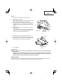
4. Replacing carbon brushes:
Remove the brush caps with a slotted-head screwdriver. The
carbon brushes can then be easily removed. (Fig. 18)
5. Performance checkup and maintenance of safety cover
Keep the safety cover in good shape for smooth performance
at all times. Be sure to make prompt repair in case of any
malfunction.
6. Adjusting the base and saw blade to maintain
perpendicularity
The angle between the base and the saw blade has been
adjusted to 90°, however should this perpendicularity be lost
for some reason, adjust in the following manner.
Fig. 18
Brush Cap
Slotted-head
Screwdriver
(1) Turn the base face up (Fig. 19) and loosen the lever (A).
(2) Apply a square to the base and the saw blade and, turning
the slotted set screw with a slotted-head screwdriver, shift the
position of the base to produce the desired right angle.
7. Service parts list
CAUTION:
Repair, modifi cation and inspection of Hitachi Power Tools must be carried out by a Hitachi Authorized
Service Center.
This Parts List will be helpful if presented with the tool to the Hitachi Authorized Service Center when
requesting repair or other maintenance. In the operation and maintenance of power tools, the safety
regulations and standards prescribed in each country must be observed.
MODIFICATIONS:
Hitachi Power Tools are constantly being improved and modifi ed to incorporate the latest technological advancements.
Accordingly, some parts (i.e. code numbers and/or design) may be changed without prior notice.
Fig. 19
Square
Slotted Set Screw
Base

English
16
ACCESSORIES
WARNING:
Accessories for this power tool are mentioned in this Instruction Manual.
The use of any other attachment or accessory can be dangerous and could cause injury or mechanical
damage.
NOTE:
Accessories are subject to change without any obligation on the part of the HITACHI.
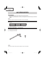
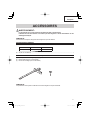
STANDARD ACCESSORIES
(1) Saw Blade ................................................................................................................................................................ 1
(2) Wrench (Code No. 320976) ....................................................................................................................................... 1
OPTIONAL ACCESSORIES.......sold separately
(1) Guide (Code No. 302691) (Includes (2) and (3).)
(2) Wing Bolt (B) (Code No. 302697)
(3) Lock Spring (Code No. 947859)
NOTE:
Specifi cations are subject to change without any obligation on the part of the HITACHI.
External Diam. Hole Diam. Code No.
7-1/4" (185 mm) 5/8" (15.9 mm) 320843

Français
17
INFORMATIONS IMPORTANTES DE SÉCURITÉ
Lire et comprendre toutes les précautions de sécurité, les avertissements et les instructions de fonctionnement dans ce
mode d’emploi avant d’utiliser ou d’entretenir cet outil motorisé.
La plupart des accidents causés lors de l’utilisation ou de l’entretien de l’outil motorisé proviennent d’un non respect des
règles ou précautions de base de sécurité. Un accident peut la plupart du temps être évité si l’on reconnaît une situation
de danger potentiel avant qu’elle ne se produise, et en observant les procédures de sécurité appropriées.
Les précautions de base de sécurité sont mises en évidence dans la section “SECURITE” de ce mode d’emploi et dans
les sections qui contiennent les instructions de fonctionnement et d’entretien.
Les dangers qui doivent être évités pour prévenir des blessures corporelles ou un endommagement de la machine sont
identifi és par AVERTISSEMENTS sur l’outil motorisé et dans ce mode d’emploi.
NE JAMAIS utiliser cet outil motorisé d’une manière qui n’est pas spécifi quement recommandée par HITACHI.
SIGNIFICATION DES MOTS D’AVERTISSEMENT
AVERTISSEMENT indique des situations potentiellement dangereuses qui, si elles sont ignorées, pourraient entraîner la
mort ou de sérieuses blessures.
PRECAUTION indique des situations dangereuses potentilles qui, si elles ne sont pas évitées, peuvent entraîner de
mineures et légères blessures ou endommager la machine.
REMARQUE met en relief des informations essentielles.
SIGNIFICATION DES SYMBOLES
SECURITE
AVERTISSEMENTS DE SÉCURITÉ GÉNÉRAUX CONCERNANT LES OUTILS ÉLECTRIQUES
AVERTISSEMENT:
Lire tous les avertissements de sécurité et toutes les instructions
Tout manquement à observer ces avertissements et instructions peut engendrer des chocs électriques, des
incendies et/ou des blessures graves.
Conservez tous les avertissements et toutes les instructions pour vous y référer ultérieurement.
Le terme “outil électrique”, utilisé dans les avertissements, se réfère aux outils électriques (câblé) ou aux outils à
piles (sans fi l).
1) Sécurité de l’aire de travail
a) Maintenir l’aire de travail propre et bien
éclairée.
Les endroits encombrés ou sombres sont
propices aux accidents.
b) Ne pas utiliser d’outils électriques en
présence de liquides, gaz ou poussière
infl ammables, au risque de provoquer une
explosion.
Les outils électriques créent des étincelles
susceptibles d’enfl ammer la poussière.
Symboles
AVERTISSEMENT
Les symboles suivants sont utilisés pour l’outil. Bien se familiariser avec leur signifi cation avant d’utiliser l’outil.
Lire tous les avertissements de sécurité et
toutes les instructions.
Tout manquement à observer ces avertissements
et instructions peut engendrer des chocs
électriques, des incendies et/ou des blessures
graves.
Toujours porter des verres de protection.
Porter des protections anti-bruit en permanence.

Français
18
c) Ne pas laisser les enfants et les visiteurs
s’approcher de vous lorsque vous utiliser
un outil électrique.
Les distractions peuvent faire perdre le contrôle.
2) Sécurité électrique
a) Les prises de l’outil électrique doivent
correspondre à la prise secteur.
Ne jamais modifi er la prise.
Ne pas utiliser d’adaptateurs avec les outils
électriques mis à la masse.
Les prises non modifi ées et les prises secteurs
correspondantes réduisent les risques de choc
électrique.
b) Eviter tout contact avec les surfaces mises
à la masse telles que les tuyaux, radiateurs,
bandes et réfrigérateurs.
Le risque de choc électrique est accru en cas
de mise à la masse du corps.
c) Ne pas exposer les outils électriques à la
pluie ou à des conditions humides.
Si l’eau pénètre dans l’outil, cela augmente les
risques de choc électrique.
d) Ne pas utiliser le cordon à tort. Ne jamais
utiliser le cordon pour transporter ou
débrancher l’outil électrique.
Maintenir le cordon loin de la chaleur, de
l’huile, des bords pointus ou des pièces
mobiles.
Les cordons endommagés ou usés augmentent
les risques de choc électrique.
e) En cas d’utilisation d’un outil électrique à
l’extérieur, utiliser un cordon de rallonge
adapté à un usage extérieur.
L’utilisation d’un cordon adapté à l’usage
extérieur réduit les risques de choc électrique.
f) Si vous devez utiliser un outil électrique
dans un endroit humide, utilisez une
alimentation protégée contre les courants
résiduels.
L’utilisation d’un dispositif de protection contre
les courants résiduels réduit le risque de choc
électrique.
3) Sécurité personnelle
a) Restez alerte, regarder ce que vous faites
et usez de votre bon sens en utilisant un
outil électrique.
Ne pas utiliser d’outil électrique si vous
êtes sous l’infl uence de drogues, d’alcool
ou de médicaments.
Pendant l’utilisation d’outils électrique, un instant
d’inattention peut entraîner des blessures graves.
b) Utiliser un équipement de protection
individuelle. Toujours porter des verres de
protection.
L’utilisation d’équipements de protection tels
que les masques anti-poussière, les chaussures
de sécurité anti-dérapantes, les casques ou
les protections auditives dans des conditions
appropriées réduisent les risques de blessures.
c) Empêcher les démarrages intempestifs. Veiller
à ce que l’interrupteur soit en position d’arrêt
avant de brancher à une source d’alimentation
et/ou une batterie, de ramasser l’outil au sol
ou de le transporter.
Transporter les outils électriques avec le
doigt sur l’interrupteur ou brancher les outils
électriques avec l’interrupteur en position de
marche peut entraîner des accidents.
d) Retirer toute clé de sécurité ou clé avant de
mettre l’outil électrique en marche.
Laisser une clé ou une clé de sécurité sur
une partie mobile de l’outil électrique peut
engendrer des blessures.
e) Ne pas trop se pencher. Toujours garder
une bonne assise et un bon équilibre
pendant le travail.
Cela permet un meilleur contrôle de l’outil
électrique dans des situations imprévisibles.
f) Porter des vêtements adéquats. Ne pas
porter de vêtements amples ni de bijoux.
Maintenir les cheveux, les vêtements et les
gants loin des pièces mobiles.
Les vêtements amples ou les cheveux longs
peuvent se prendre dans les pièces mobiles.
g) En cas de dispositifs destinés au raccordement
d’installations d’extraction et de recueil
de la poussière, veiller à ce qu’ils soient
correctement raccordés et utilisés.
L’utilisation d’un dispositif de collecte de la
poussière peut réduire les dangers associés à la
poussière.
4) Utilisation et entretien d’un outil électrique
a) Ne pas forcer sur l’outil électrique. Utiliser
l’outil électrique adapté à vos travaux.
Le bon outil électrique fera le travail mieux et
en toute sécurité au régime pour lequel il a été
conçu.
b) Ne pas utiliser l’outil électrique si l’interrupteur
ne le met pas en position de marche et d’arrêt.
Tout outil ne pouvant être contrôlé par
l’interrupteur est dangereux et doit être réparé.
c) Débrancher la prise ou retirer la batterie avant
de procéder à des réglages, au remplacement
des accessoires ou au stockage des outils
électriques.
Ces mesures préventives de sécurité réduisent
les risques de démarrage accidentel de l’outil
électrique.
d) Stockez les outils électriques inutilisés hors
de la portée des enfants et ne pas laisser
des personnes non familiarisées avec l’outil
ou ces instructions utiliser l’outil électrique.
Les outils électriques sont dangereux entre les
mains d’utilisateurs non habilités.

Français
19
e) Entretenir les outils électriques. Vérifier
l’absence de mauvais alignement ou d’arrêt,
d’endommagement de pièces ou toute autre
condition susceptible d’aff ecter l’opération
de l’outil.
Si l’outil est endommagé, le faire réparer
avant utilisation.
De nombreux accidents sont dus à des outils
mal entretenus.
f) Maintenir les outils coupants aiguisés et
propres.
Des outils coupants bien entretenus avec des
bords aiguisés sont moins susceptibles de se
coincer et plus simples à contrôler.
g) Utiliser l’outil électrique, les accessoires
et les mèches de l’outil, etc. conformément
à ces instructions en tenant compte des
conditions d’utilisation et du travail à réaliser.
L’utilisation de l’outil électrique pour des
opérations diff érentes de celles pour lesquelles il
a été conçu est dangereuse.
5) Service
a) Faire entretenir l’outil électrique par un
technicien habilité à l’aide de pièces de
rechange identiques exclusivement.
Cela garantira le maintien de la sécurité de l’outil
électrique.
AVERTISSEMENTS DE SÉCURITÉ
RELATIFS À LA SCIE CIRCULAIRE
Procédures de coupe
a) DANGER: N’approchez pas les mains de la
zone de coupe et de la lame. Gardez la deuxième
main sur la poignée auxiliaire ou sur le boîtier du
moteur.
Si les deux mains tiennent la scie, elles ne peuvent
pas être coupées par la lame.
b) N’exposez aucune partie de votre corps sous
la pièce à travailler.
Le protecteur ne peut pas vous protéger de la
lame sous la pièce à travailler.
c) Ajustez la profondeur de coupe à l’épaisseur
de la pièce à travailler.
Il convient que moins de la totalité d’une dent
parmi toutes les dents de la lame soit visible sous
la pièce à travailler.
d) Ne tenez jamais la pièce à débiter dans vos
mains ou sur vos jambes. Assurezvous que
la pièce à travailler se trouve sur une plate-
forme stable.
Il est important que la pièce à travailler soit
soutenue convenablement, afi n de minimiser l’exposition
du corps, le grippage de la lame, ou la perte de
contrôle.
e) Maintenez l’outil uniquement par les surfaces
de prise isolantes, si l’outil coupant, en marche,
peut être en contact avec des conducteurs
cachés ou avec son propre cordon d’alimentation.
Le contact avec un fil “sous tension” mettra
également “sous tension” les parties métalliques
exposées de l’outil et pourra provoquer un choc
électrique sur l’opérateur.
f) Lors d’une coupe, utilisez toujours un guide
parallèle ou un guide à bords droits.
Cela améliore la précision de la coupe et réduit
les risques de grippage de la lame.
g) Utilisez toujours des lames dont la taille et la
forme (diamètre et rond) des alésages centraux
sont convenables.
Les lames qui ne correspondent pas aux éléments
de montage de la scie ne fonctionneront pas bien,
provoquant une perte de contrôle.
h) N’utilisez jamais de rondelles ou de boulons
de lames endommagés ou inadaptés.
Les rondelles et les boulons de lames ont été
spécialement conçus pour votre scie, afin de
garantir une performance optimale et une sécurité
de fonctionnement.
Causes du recul et mises en garde correspondantes
– le recul est une réaction soudaine observée sur
une lame de scie pincée, bloquée ou mal alignée,
faisant sortir la scie de la pièce à travailler de
manière incontrôlée dans la direction de l’opérateur;
– lorsque la lame est pincée ou bloquée fermement
par le fond du trait de scie, la lame se bloque
et le moteur fait retourner brutalement le bloc à
l’opérateur;
– si la lame se tord ou est mal alignée lors de la
coupe, les dents sur le bord arrière de la lame
peuvent creuser la face supérieure du bois, ce qui
fait que la lame sort du trait de scie et est projetée
sur l’opérateur.
Le recul est le résultat d’un mauvais usage de la scie et/
ou de procédures ou de conditions de fonctionnement
incorrectes et peut être évité en prenant les précautions
adéquates spécifi ées ci-dessous.
a) Maintenez fermement la scie avec les deux
mains et positionnez vos bras afi n de résister
aux forces de recul. Positionnez votre corps d’un
des côtés de la lame, mais pas dans l’alignement
de la lame.
Le recul peut faire revenir la scie en arrière, mais
les forces de recul peuvent être maîtrisées par
l’opérateur, si les précautions adéquates sont prises.
b) Lorsque la lame est grippée ou lorsqu’une
coupe est interrompue pour quelque raison que
ce soit, relâchez le bouton de commande et
maintenez la scie immobile dans le matériau,
jusqu’à ce que la lame arrête complètement de
fonctionner.
N’essayez jamais de retirer la scie de la pièce
à travailler ou tirez la scie en arrière pendant
que la lame est en mouvement ou que le recul
peut se produire.
Recherchez et prenez des mesures correctives afi n
d’empêcher que la lame ne se grippe.

Français
20
c) Lorsque vous remettez en marche une scie
dans la pièce à travailler, centrez la lame de
scie dans le trait de scie et vérifiez que les
dents de la scie ne soient pas rentrées dans le
matériau.
Si la lame de scie est grippée, elle peut venir
chevaucher la pièce à travailler ou en sortir lorsque
la scie est remise en fonctionnement.
d) Placez des panneaux de grande taille sur
un support afin de minimiser les risques de
pincement de la lame et de recul.
Les grands panneaux ont tendance à fl échir sous
leur propre poids. Les supports doivent être placés
sous le panneau des deux cotés, près de la ligne
de coupe et près du bord du panneau.
e) N’utilisez pas de lames émoussées ou
endommagées.
Des lames non aiguisées ou mal fi xées entraînent
un trait de scie rétréci, provoquant trop de
frottements, un grippage de la lame et un recul.
f) La profondeur de la lame et les leviers de
verrouillage et de réglage du biseau doivent être
solides et stables avant de réaliser la coupe.
Si l’ajustement de la lame dérive pendant la
coupe, cela peut provoquer un grippage et un
recul.
g) Soyez d’autant plus prudent lorsque vous
découpez des parois existantes ou d’autres
zones sans visibilité.
La lame saillante peut couper des objets qui
peuvent entraîner un recul.
Fonctionnement du protecteur inférieur
a) Vérifiez que le protecteur inférieur soit bien
fermé avant chaque utilisation.
Ne mettez pas la scie en marche si le
protecteur inférieur ne se déplace pas librement
et ne se ferme pas instantanément. Ne serrez
jamais ou n’attachez jamais le protecteur
inférieur en position ouverte.
Si la scie tombe accidentellement, le protecteur
inférieur peut se tordre. Soulevez le protecteur
inférieur avec la poignée rétractive et assurez-vous
qu’il bouge librement et n’est pas en contact avec
la lame ou toute autre partie, à tous les angles et
profondeurs de coupe.
b) Vérifiez le fonctionnement du ressort du
protecteur inférieur. Si le protecteur et le ressort
ne fonctionnent pas correctement, ils doivent
être révisés avant utilisation.
Le protecteur inférieur peut fonctionner lentement
en raison d’éléments endommagés, de dépôts
collants ou de l’accumulation de débris.
c) Le protecteur inférieur peut revenir se loger
manuellement uniquement pour les coupes
particulières telles que les “coupes plongeantes”
et les “coupes complexes”. Soulevez le protecteur
inférieur par la poignée rétractive et dès que
la lame entre dans le matériau, le protecteur
inférieur doit être relâché.
Pour toutes les autres découpes, il convient que le
protecteur inférieur fonctionne automatiquement.
d) Vérifiez toujours que le protecteur inférieur
recouvre la lame avant de poser la scie sur
un établi ou sur le sol.
Une lame non protégée et continuant à fonctionner
par inertie entraînera la scie en arrière, et coupera
alors tout ce qui se trouve sur sa trajectoire. Soyez
conscient du temps nécessaire à la lame pour s’arrêter
après que l’interrupteur est relâché.
RRÈGLES DE SÉCURITÉ SPÉCIFIQUES ET
SYMBOLES
1. Reglages. Avant de couper, bien vérifier que
les réglages de profondeur et de biseau sont
solides.
2. Eviter de couper des clous. Avant de couper,
vérifi er s’il y a des clous dans le matériau et les
retirer le cas échéant.
3. Lors du fonctionnement de la scie, tenir le
cordon éloigné de la zone de coupe et le placer
de façon qu’il ne soit pas pris dans la pièce
pendant l’opération de coupe.
Utiliser un support de main approprié, un support de
pièce approprié, et acheminer le cordon loin de la
zone de travail.
AVERTISSEMENT:
Il est important de soutenir la pièce correctement et
de tenir solidement la scie pour éviter toute perte de
contrôle pouvant entraîner des blessures physiques.
La Fig. 1 donne un exemple type de soutien manuel
de la scie.
4. Placer la section large de l’embase de la scie
sur la section de la pièce qui est fermement
soutenue, et non sur la section qui va tomber
après la coupe.
A titre d’exemples, la Fig. 2 montre la façon
CORRECTE de couper l’extrémité de la planche, et
la Fig. 3 montre la façon INCORRECTE. Si la pièce
est trop courte ou trop petite, la fi xer.
NE PAS ESSAYER DE TENIR LES SECTIONS
COURTES À LA MAIN!
EXEMPLE TYPE DE SOUTIEN MANUEL
DE LA SCIE ET, SOUTIEN LA PIÈCE ET
D’ACHEMINEMENT DU CORDON.
Fig. 1
La page charge ...
La page charge ...
La page charge ...
La page charge ...
La page charge ...
La page charge ...
La page charge ...
La page charge ...
La page charge ...
La page charge ...
La page charge ...
La page charge ...
La page charge ...
La page charge ...
La page charge ...
La page charge ...
La page charge ...
La page charge ...
La page charge ...
La page charge ...
La page charge ...
La page charge ...
La page charge ...
La page charge ...
La page charge ...
La page charge ...
La page charge ...
La page charge ...
-
 1
1
-
 2
2
-
 3
3
-
 4
4
-
 5
5
-
 6
6
-
 7
7
-
 8
8
-
 9
9
-
 10
10
-
 11
11
-
 12
12
-
 13
13
-
 14
14
-
 15
15
-
 16
16
-
 17
17
-
 18
18
-
 19
19
-
 20
20
-
 21
21
-
 22
22
-
 23
23
-
 24
24
-
 25
25
-
 26
26
-
 27
27
-
 28
28
-
 29
29
-
 30
30
-
 31
31
-
 32
32
-
 33
33
-
 34
34
-
 35
35
-
 36
36
-
 37
37
-
 38
38
-
 39
39
-
 40
40
-
 41
41
-
 42
42
-
 43
43
-
 44
44
-
 45
45
-
 46
46
-
 47
47
-
 48
48


Hikoki C 7SB2 Manuel utilisateur
- Catégorie
- Outils électroportatifs
- Taper
- Manuel utilisateur
- Ce manuel convient également à
dans d''autres langues
- English: Hikoki C 7SB2 User manual
- español: Hikoki C 7SB2 Manual de usuario
Documents connexes
Autres documents
-
Hitachi C 7SB2 Safety Instructions And Instruction Manual
-
-
-
-
-
Hitachi C7SB2 Manuel utilisateur
-
-
-
-
Milwaukee 6430-20 Manuel utilisateur