
52022032 REV 2 © 2019 Greenlee Tools, Inc. 9/19
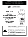
CM-410
Digital
Clamp-on Meter
Medidor digital
con pinza
Contrôleur
numérique
à pince
INSTRUCTION MANUAL
MANUAL DE INSTRUCCIONES
MANUEL D’INSTRUCTIONS
Read and understand all of the instructions and
safety information in this manual before
operating or servicing this tool.
Lea y entienda todas las instrucciones y la
información sobre seguridad que aparecen en
este manual, antes de manejar esta herramienta
o darle mantenimiento.
Lire attentivement et bien comprendre toutes les
instructions et les informations sur la sécurité de
ce manuel avant d‘utiliser ou de procéder à
l‘entretien de cet outil.

2
Description
The Greenlee CM-410 Digital Clamp-on Meter is a hand-held testing device
capable of measuring up to 400 amps of alternating current, in addition to
measuring AC or DC voltage, resistance, and checking continuity.
Safety
Safety is essential in the use and maintenance of Greenlee tools and
equipment. This instruction manual and any markings on the tool provide
information for avoiding hazards and unsafe practices related to the use of
this tool. Observe all of the safety information provided.
Purpose of This Manual
This instruction manual is intended to familiarize all personnel with the
safe operation and maintenance procedures for the Greenlee CM-410
Digital Clamp-on Meter.
Keep this manual available to all personnel.
Replacement manuals are available upon request at no charge:
www.greenlee.com.
KEEP THIS MANUAL
All specifications are nominal and may change as design improvements occur.
Greenlee
Tools,
Inc. shall not be liable for damages resulting from misapplication or
misuse of its products.
® Registered: The color green for electrical test instruments is a registered trademark
of Greenlee
Tools,
Inc.
Do not discard this product or throw away!
For recycling information, go to www.greenlee.com.

3
CM-410
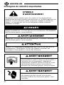
Important Safety Information
Electric shock hazard:
Contact with live circuits could result in severe
injury or death.
Read and understand this material before
operating or servicing this equipment. Failure to
understand how to safely operate this tool could
result in an accident causing serious injury or
death.
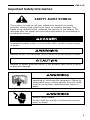
This symbol is used to call your attention to hazards or unsafe
practices which could result in an injury or property damage. The
signal word, defined below, indicates the severity of the hazard. The
message after the signal word provides information for preventing or
avoiding the hazard.
SAFETY ALERT SYMBOL
Immediate hazards which, if not avoided, WILL result in severe injury
or death.
Hazards which, if not avoided, COULD result in severe injury or death.
Hazards or unsafe practices which, if not avoided, MAY result in injury
or property damage.

4
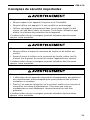
Important Safety Information
Electric shock and fire hazard:
• Do not expose this unit to rain or moisture.
• Do not use the unit if it is wet or damaged.
• Use this unit for the manufacturer’s intended purpose only, as
described in this manual. Any other use can impair the protection
provided by the unit.
Failure to observe these warnings could result in severe injury or death.
Electric shock hazard:
• Do not operate with the case or battery door open.
• Before opening the case or battery door, remove the test leads
(or jaw) from the circuit and shut off the unit.
Failure to observe these warnings could result in severe injury or death.
Electric shock hazard:
• Using this unit near equipment that generates electromagnetic
interference can result in unstable or inaccurate readings.
• Unless measuring voltage or current, shut off and lock out power.
Make sure that all capacitors are discharged. Voltage must not be
present.
Failure to observe these warnings could result in severe injury or death.

5
CM-410
Electric shock hazard:
• Do not attempt to repair this unit. It contains no user-serviceable
parts.
• Do not expose the unit to extremes in temperature or high humidity.
Refer to “Specifications.”
Failure to observe these precautions may result in injury and can
damage the unit.
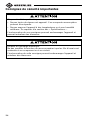
Important Safety Information
Electric shock hazard:
Do not change the measurement function while the test leads are
connected to a component or circuit.
Failure to observe this precaution may result in injury and can damage
the unit.

6
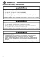
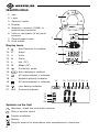
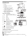
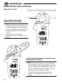
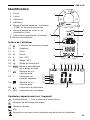
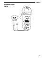
Identification
1. Jaw
2. Lever
3. Selector switch
4. Display
5. Negative, common (COM), or
ground input terminal
6. Volts or resistance (V-Ω) input
terminal
7. Select/toggle button
8. Hold button
910111213141516
17
18
19
20
21
1
3
4
5
2
8
7
6
Symbols on the Unit
Warning—Read the instruction manual
Risk of electric shock
Double insulation
Battery
Recycle product in accordance with manufacturer’s directions
Display Icons
9. Hold function is enabled.
10. A Amps
11. V Volts
12. Ω Ohms
13. k kilo (10
3
)
14. M Mega (10
6
)
15. Continuity mode
16. Auto ranging is enabled.
17. AC measurement is selected.
18. – Negative polarity indicator
19. DC measurement is selected.
20. Low battery indicator
21.
O.L
Overload indicator

7
CM-410
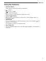
Using the Features
• Selector Switch
Slide switch to desired mode of operation:
(amps)
(AC/DC voltage)
(ohms/continuity)
Return switch to OFF position when not in use.
• Select/Toggle Button
Momentarily press button to select AC or DC voltage, ohms, or
continuity mode.
• Hold Button
Press momentarily to hold the present value on the display.
will
appear on the display.
Press again to return to normal mode.
• Auto Power Off
The unit automatically shuts off after approximately 10 minutes of
inactivity.

8
Operation
1. Set the selector switch according to the Settings Table. Momentarily
press the select/toggle button to select mode.
2. Refer to “Typical Measurements” for specific measurement
instructions.
3. Test the unit on a known functioning circuit or component.
• If the unit does not function as expected on a known functioning
circuit, replace the battery.
• If the unit still does not function as expected, send the unit to
Greenlee for repair. Refer to the instructions under the Warranty.
4. Take the reading from the circuit or component to be tested.
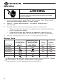
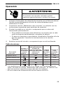
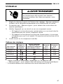
Settings Table
Electric shock hazard:
Contact with live circuits could result in severe
injury or death.
To measure
this value …
Connect
red lead
to …
Connect
black lead
to …
Momentarily press
the Select/Toggle
Button until this
icon appears
on the display …
Set the
Selector Switch
to this
symbol …
AC Amps* N/A N/AN/A
AC Voltage V-Ω COM
DC Voltage V-Ω COM
Continuity** V-Ω COM
Resistance V-Ω COM
M Ω
*AC Amp measurements are made using the jaw clamp. Refer to “Typical
Measurements” for specific measurement instructions.
**Tone indicates a circuit resistance of less than 20 Ω.

9
CM-410
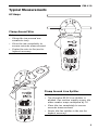
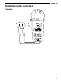
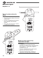
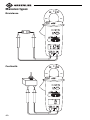
Typical Measurements
Clamp Around Line Splitter
Notes:
• The Greenlee 93-30 Line Splitter is
divided. One section renders amps; the
other renders amps multiplied by 10.
• Close the jaw completely to ensure
accurate measurement.
• Center the line splitter in the jaw for
highest accuracy.
Clamp Around Wire
Notes:
• Clamp the jaw around one
conductor only.
• Close the jaw completely to
ensure accurate measurement.
• Center the wire in the jaw for
highest accuracy.
AC Amps

10
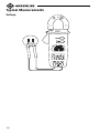
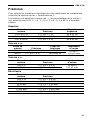
Typical Measurements
Voltage

11
CM-410
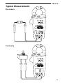
Typical Measurements
Resistance
Continuity

12
Accuracy
Refer to “Specifications” for operating conditions and temperature
coefficient.
Accuracy is specified as follows: ± (a percentage of the reading + a fixed
amount) at 23 °C ± 5 °C (73.4 °F ± 9 °F), 0% to 80% relative humidity.
Amps
Measurement Frequency
Range Accuracy Range
0.0 to 40.0 A ± (1.9% + 1 A) 50 to 60 Hz
40.0 to 200.0 A ± (1.9% + 0.5 A) 50 to 60 Hz
201 to 400 A ± (1.9% + 5 A) 50 to 60 Hz
AC Voltage
Measurement Frequency Input
Range Accuracy Range Impedance
200.0 V ± (1.5% + 0.5 V) 50 to 500 Hz
10 MΩ //
600 V ± (1.5% + 5 V) 50 to 500 Hz
100 pF max
DC Voltage
Measurement Input
Range Accuracy Impedance
200.0 V ± (1.0% + 0.2 V)
10 MΩ //
600 V ± (1.0% + 2 V)
100 pF max
Resistance
Measurement
Range Accuracy
200.0 Ω± (1.2% + 0.5 Ω)
2.000 kΩ± (0.7% + 0.002 kΩ)
20.00 kΩ± (0.7% + 0.02 kΩ)
200.0 kΩ± (0.7% + 0.2 kΩ)
2.000 MΩ± (1.0% + 0.002 MΩ)
20.00 MΩ± (1.9% + 0.05 MΩ)

13
CM-410
Specifications
Display: 3-1/2-digit LCD (1999 maximum reading)
Sampling Rate: 1.5 per second
Overrange Indication: “OL” appears on the display
Jaw Opening: 30 mm (1.18")
Maximum Conductor Diameter: 27 mm (1.06")
Measurement Category: Category III, 600 V
Temperature Coefficient: 0.2 x (specified accuracy) per °C
below 18 °C or above 28 °C
Operating Conditions:
At 0% ≤ 80% RH: 0 °C to 30 °C (32 °F to 86 °F)
At 0% ≤ 75% RH: 30 °C to 40 °C (86 °F to 104 °F)
At 0% ≤ 45% RH: 40 °C to 50 °C (104 °F to 122 °F)
Altitude: 2000 m (6500') maximum
Indoor use only
Storage Conditions: -20 °C to 60 °C (-4 °F to 140° F),
0% to 80% relative humidity with battery removed
Pollution Degree: 2
Battery: Two 1.5 V (AAA, A4M, or IEC LR03)

14
Measurement Categories
These definitions were derived from the international safety standard for
insulation coordination as it applies to measurement, control, and
laboratory equipment. These measurement categories are explained in
more detail by the International Electrotechnical Commission; refer to
either of their publications: IEC 61010-1 or IEC 60664.
Measurement Category I
Signal level. Electronic and telecommunication equipment, or parts thereof.
Some examples include transient-protected electronic circuits inside
photocopiers and modems.
Measurement Category II
Local level. Appliances, portable equipment, and the circuits they are
plugged into. Some examples include light fixtures, televisions, and long
branch circuits.
Measurement Category III
Distribution level. Permanently installed machines and the circuits they are
hard-wired to. Some examples include conveyor systems and the main
circuit breaker panels of a building’s electrical system.
Measurement Category IV
Primary supply level. Overhead lines and other cable systems. Some
examples include cables, meters, transformers, and other exterior
equipment owned by the power utility.
Statement of Conformity
Greenlee Tools, Inc. is certified in accordance with ISO 9000 (2000) for
our Quality Management Systems.
The instrument enclosed has been checked and/or calibrated using
equipment that is traceable to the National Institute for Standards and
Technology (NIST).

15
CM-410
Maintenance
Electric shock hazard:
• Do not attempt to repair this unit. It contains no user-serviceable
parts.
• Do not expose the unit to extremes in temperature or high humidity.
Refer to “Specifications.”
Failure to observe these precautions may result in injury and can
damage the unit.
Battery Replacement
Electric shock hazard:
• Do not operate with the case or battery door open.
• Before opening the case or battery door, remove the test leads
(or jaw) from the circuit and shut off the unit.
Failure to observe these warnings could result in severe injury or death.
1. Disconnect the unit from the circuit. Turn the unit OFF.
2. Remove the screw from the battery door.
3. Remove the battery door.
4. Replace the batteries (observe polarity).
5. Replace the battery door and the screw.
Cleaning
Periodically wipe the case with a damp cloth and mild detergent; do not
use abrasives or solvents.

16

17
CM-410
Descripción
El Medidor digital con pinza modelo CM-410 de Greenlee es un
instrumento de verificación capaz de medir hasta 400 amperios de
corriente alterna, además de medir tensión alterna o continua, resistencia y
verificar continuidad. Esta unidad es de bolsillo y cabe perfectamente en la
palma de la mano.
Acerca de la seguridad
Es fundamental observar métodos seguros al utilizar y dar mantenimiento
a las herramientas y equipo Greenlee. Este manual de instrucciones y todas
las marcas que ostenta la herramienta le ofrecen la información necesaria
para evitar riesgos y hábitos poco seguros relacionados con su uso. Siga
toda la información sobre seguridad que se proporciona.
Propósito de este manual
Este manual de instrucciones tiene como propósito familiarizar a todo el
personal con los procedimientos de operación y mantenimiento seguros
para el Medidor digital con pinza, modelo CM-410 de Greenlee.
Manténgalo siempre al alcance de todo el personal.
Puede obtener copias adicionales de manera gratuita, previa solicitud:
www.greenlee.com.
CONSERVE ESTE MANUAL
Todas las especificaciones son nominales y pueden cambiar conforme tengan lugar
mejoras de diseño. Greenlee
Tools
, Inc. no se hace responsable de los daños que
puedan surgir de la mala aplicación o mal uso de sus productos.
® Registrado: El color verde para instrumentos de verificación eléctricos es una marca
registrada de Greenlee
Tools
, Inc.
¡No deseche ni descarte este producto!
Para información sobre reciclaje, visite www.greenlee.com.

18
Importante Información sobre Seguridad
Peligro de electrocución:
El contacto con circuitos activados podría
ocasionar graves lesiones o incluso la muerte.
Lea y entienda este documento antes de
manejar esta herramienta o darle mantenimiento.
Utilizarla sin comprender cómo manejarla de
manera segura podría ocasionar un accidente y,
como resultado de éste, graves lesiones o
incluso la muerte.
Este símbolo se utiliza para indicar un riesgo o práctica poco segura
que podría ocasionar lesiones o daños materiales. Cada uno de los
siguientes términos denota la gravedad del riesgo. El mensaje que
sigue a dichos términos le indica cómo puede evitar o prevenir ese
riesgo.
SÍMBOLO DE ALERTA
SOBRE SEGURIDAD
Peligros inmediatos que, de no evitarse, OCASIONARÁN graves
lesiones o incluso la muerte.
Peligros que, de no evitarse, PODRÍAN OCASIONAR graves lesiones o
incluso la muerte.
Peligro o prácticas peligrosas que, de no evitarse, PUEDEN
OCASIONAR lesiones o daños materiales.

19
CM-410
Importante Información sobre Seguridad
Peligro de electrocución:
• No haga funcionar esta unidad con la caja o la puerta del
compartimiento de las baterías abierta.
• Antes de abrir la caja o la puerta del compartimiento de las baterías,
retire del circuito los cables de prueba (o la pinza), y apague la
unidad.
De no observarse estas advertencias podrían sufrirse graves lesiones o
incluso la muerte.
Peligro de electrocución e incendio:
• No exponga esta unidad ni a la lluvia ni a la humedad.
• No utilice esta unidad si se encuentra mojada o dañada.
• Utilícela únicamente para el propósito para el que ha sido diseñada
por el fabricante, tal como se describe en este manual. Cualquier
otro uso puede menoscabar la protección proporcionada por la
unidad.
De no observarse estas advertencias podrían sufrirse graves lesiones o
incluso la muerte.
Peligro de electrocución:
• Al utilizar esta unidad cerca de equipo que genere interferencia
electromagnética quizá se obtenga una lectura inexacta e inestable.
• A menos que vaya a medir tensión o corriente, apague y bloquee la
energía. Asegúrese que todos los condensadores estén totalmente
sin carga. No debe haber tensión alguna.
De no observarse estas advertencias podrían sufrirse graves lesiones o
incluso la muerte.

20
Importante Información sobre Seguridad
Peligro de electrocución:
No cambie la función de medición mientras los cables de prueba estén
conectados a un componente o circuito.
De no observarse esta advertencia podrían sufrirse lesiones o daños a
la unidad.
Peligro de electrocución:
• No intente reparar esta unidad, ya que contiene partes que deben
recibir mantenimiento por parte de un profesional.
• No exponga la unidad a ambientes de temperatura extrema o altos
niveles de humedad. Consulte la sección “Especificaciones”.
De no observarse estas precauciones podrían sufrirse lesiones o daños
a la unidad.
La page est en cours de chargement...
La page est en cours de chargement...
La page est en cours de chargement...
La page est en cours de chargement...
La page est en cours de chargement...
La page est en cours de chargement...
La page est en cours de chargement...
La page est en cours de chargement...
La page est en cours de chargement...
La page est en cours de chargement...
La page est en cours de chargement...
La page est en cours de chargement...
La page est en cours de chargement...
La page est en cours de chargement...
La page est en cours de chargement...
La page est en cours de chargement...
La page est en cours de chargement...
La page est en cours de chargement...
La page est en cours de chargement...
La page est en cours de chargement...
La page est en cours de chargement...
La page est en cours de chargement...
La page est en cours de chargement...
La page est en cours de chargement...
La page est en cours de chargement...
La page est en cours de chargement...
La page est en cours de chargement...
La page est en cours de chargement...
-
 1
1
-
 2
2
-
 3
3
-
 4
4
-
 5
5
-
 6
6
-
 7
7
-
 8
8
-
 9
9
-
 10
10
-
 11
11
-
 12
12
-
 13
13
-
 14
14
-
 15
15
-
 16
16
-
 17
17
-
 18
18
-
 19
19
-
 20
20
-
 21
21
-
 22
22
-
 23
23
-
 24
24
-
 25
25
-
 26
26
-
 27
27
-
 28
28
-
 29
29
-
 30
30
-
 31
31
-
 32
32
-
 33
33
-
 34
34
-
 35
35
-
 36
36
-
 37
37
-
 38
38
-
 39
39
-
 40
40
-
 41
41
-
 42
42
-
 43
43
-
 44
44
-
 45
45
-
 46
46
-
 47
47
-
 48
48


Greenlee CM-410 Digital Clamp-on Meter Manuel utilisateur
- Taper
- Manuel utilisateur
- Ce manuel convient également à
dans d''autres langues
Documents connexes
-
Greenlee CM-410 Digital Clamp-on Meter (Europe) Manuel utilisateur
-
-
Greenlee DM-25 Digital Multimeter Manuel utilisateur
-
-
-
-
-
-
Greenlee CMT-90 Clamp-on Meter with Diode Test Manuel utilisateur
-