
INTERFACE UNIT
PFV-L10
OPERATION MANUAL
[Japanese/English]
1st Edition (Revised 1)

,
,
1
2
3

1 (J)
..............................................................................................................
2 (J)
..............................................................................................................
3 (J)
................................................................................................................
4 (J)
.............................................................................................
6 (J)
.................................................................................................................
8(J)

2 (J)
•
•
•
•
•
•


4 (J)
2
BKPF-L601C A/D
BKPF-L602C D/A
BKPF-L603 SDI
BKPF-L605
/NTSC
BKPF-L606 /
/NTSC
BKPF-L608C
BKPF-L611 3 SDI


6 (J)
INTERFACE UNIT
PFV-L10
POWER
B
I
O
POWER
A
I
O
1
A
3
B
4
POWER B
2
POWER A
5
7
STATUS OUT
3
B
•
•
•
•
4
POWER ( ) B
6
U
( )
8
AC IN A
9
AC IN B
1
A
•
•
•
•
2
POWER ( ) A
U
A
B
-AC IN
STATUS OUT


1 (E)
English
WARNING: THIS WARNING IS APPLICABLE FOR USA
ONLY.
If used in USA, use the UL LISTED power cord specified
below.
DO NOT USE ANY OTHER POWER CORD.
Plug Cap Parallel blade with ground pin
(NEMA 5-15P Configuration)
Cord Type SJT, three 16 or 18 AWG wires
Length Less than 2.5 m (8 ft. 3in.)
Rating Minimum 10 A, 125 V
Using this unit at a voltage other than 120 V may require the
use of a different line cord or attachment plug, or both. To
reduce the risk of fire or electric shock, refer servicing to
qualified service personnel.
WARNING: THIS WARNING IS APPLICABLE FOR OTHER
COUNTRIES.
1. Use the approved Power Cord (3-core mains lead)/
Appliance Connector/Plug with earthing-contacts that
conforms to the safety regulations of each country if
applicable.
2. Use the Power Cord (3-core mains lead)/Appliance
Connector/Plug conforming to the proper ratings (voltage,
ampere).
If you have questions on the use of the above Power Cord/
Appliance Connector/Plug, please consult a qualified service
personnel.
WARNING
To prevent fire or shock hazard, do not expose the unit to
rain or moisture.
To avoid electrical shock, do not open the cabinet. Refer
servicing to qualified personnel only.
THIS APPARATUS MUST BE EARTHED.
AVERTISSEMENT
Afin d’éviter tout risque d’incendie ou d’électrocution, ne pas
exposer cet appareil à la pluie ou à l’humidité.
Afin d’écarter tout risque d’électrocution, garder le coffret
fermé. Ne confier l’entretien de l’appareil qu’à un personnel
qualifié.
CET APPAREIL DOIT ÊTRE RELIÉ À LA TERRE.
VORSICHT
Um Feuergefahr und die Gefahr eines elektrischen Schlages
zu vermeiden, darf das Gerät weder Regen noch
Feuchtigkeit ausgesetzt werden.
Um einen elektrischen Schlag zu vermeiden, darf das
Gehäuse nicht geöffnet werden. Überlassen Sie
Wartungsarbeiten stets nur qualifiziertem Fachpersonal.
DIESES GERÄT MUSS GEERDET WERDEN.
For the customers in the USA
This equipment has been tested and found to comply with
the limits for a Class A digital device, pursuant to Part 15 of
the FCC Rules. These limits are designed to provide
reasonable protection against harmful interference when the
equipment is operated in a commercial environment. This
equipment generates, uses, and can radiate radio frequency
energy and, if not installed and used in accordance with the
instruction manual, may cause harmful interference to radio
communications. Operation of this equipment in a residential
area is likely to cause harmful interference in which case the
user will be required to correct the interference at his own
expense.
You are cautioned that any changes or modifications not
expressly approved in this manual could void your authority
to operate this equipment.
The shielded interface cable recommended in this manual
must be used with this equipment in order to comply with the
limits for a digital device pursuant to Subpart B of Part 15 of
FCC Rules.
This symbol is intended to alert the user to the
presence of important operating and
maintenance (servicing) instructions in the
literature accompanying the appliance.
English

2 (E)
Overview.............................................................. 3 (E)
Features ........................................................... 3 (E)
Optional Boards............................................... 3 (E)
Locations and Functions of Parts...................... 5 (E)
Specifications....................................................... 7 (E)
For the customers in Europe
This product with the CE marking complies with both the
EMC Directive (89/336/EEC) and the Low Voltage Directive
(73/23/EEC) issued by the Commission of the European
Community.
Compliance with these directives implies conformity to the
following European standards:
• EN60950: Product Safety
• EN55103-1: Electromagnetic Interference (Emission)
• EN55103-2: Electromagnetic Susceptibility (Immunity)
This product is intended for use in the following
Electromagnetic Environment(s):
E1 (residential), E2 (commercial and light industrial), E3
(urban outdoors) and E4 (controlled EMC environment, ex.
TV studio)
Pour les clients européens
Ce produit portant la marque CE est conforme à la fois à la
Directive sur la compatibilité électromagnétique (EMC) (89/
336/CEE) et à la Directive sur les basses tensions (73/23/
CEE) émises par la Commission de la Communauté
Européenne.
La conformité à ces directives implique la conformité aux
normes européennes suivantes:
• EN60950: Sécurité des produits
• EN55103-1: Interférences électromagnétiques (émission)
• EN55103-2: Sensibilité électromagétique (immunité)
Ce produit est prévu pour être utillisé dans les
environnements électromagnétiques suivants:
E1 (résidentiel), E2 (commercial et industrie légère), E3
(urbain extérieur) et E4 (environnement EMC contrôlé ex.
studio de télévision).
Für Kunden in Europa
Dieses Produkt besitzt die CE-Kennzeichnung und erfüllt
sowohl die EMV-Direktive (89/336/EEC) als auch die
Direktive Niederspannung (73/23/EEC) der EG-Kommission.
Die Erfüllung dieser Direktiven bedeutet Konformität für die
folgenden Europäischen Normen:
• EN60950: Produktsicherheit
• EN55103-1: Elektromagnetische Interferenz (Emission)
• EN55103-2: Elektromagnetische Empfindlichkeit
(Immunität)
Dieses Produkt ist für den Einsatz unter folgenden
elektromagnetischen Bedingungen ausgelegt:
E1 (Wohnbereich), E2 (kommerzieller und in beschränktem
Maße industrieller Bereich), E3 (Stadtbereich im Freien) und
E4 (kontrollierter EMV-Bereich, z.B. Fernsehstudio).
Table of Contents

3 (E)
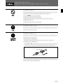
Overview
The PFV-L10 Interface Unit is an apparatus for
interfacing various kinds of equipment to process
analog and digital video and audio signals. The unit is
composed of a power block, a main board and then
slots to accommodate optional boards .
When an optional board is installed in one of the slots,
the power is supplied from the PFV-L10 to the board,
and the functions of the board are activated. Select the
appropriate optional boards and install them into the
PFV-L10, allowing the unit to execute various signal-
processing functions.
Features
Various kinds of signal processing with
optional boards
With the appropriate optional boards installed, various
functions regarding serial digital video signals can be
processed in a single PFV-L10 unit.
Up to then boards can be installed in combination in
the PFV-L10.
For the optional boards, see the next section.
Reliable operation assured by two AC lines
A pair of built-in power supply units enable the PFV-
L10 to be supplied with power from two separate lines.
If one of the power blocks stops supplying power, the
other block will supply full power. Thus, highly
reliable operation is maintained.
Rack mounting
The unit can be mounted in a standard 19-inch rack.
To mount the unit to the rack, the RMM-10 Rack
Mount Kit is necessary. For mounting the RMM-10,
consult your Sony service personnel.
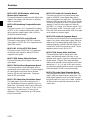
Optional Boards
Select boards with the required functions, and install
them in slots of the PFV-L10.
BKPF-L601C A/D Converter
This board converts the analog component video
signals (Y, R-Y, B-Y) or the RGB signals to the digital
signals, and supplies them as four lines of the 4:2:2
component serial digital video signals.
BKPF-L602C Video D/A Converter
This board converts the 4:2:2 serial digital video signal
to analog signals, and supplies them as the G/B/R/
SYNC or Y/B-Y/R-Y/SYNC signals.
BKPF-L603 SDI Distributor
This board distributes a composite or component serial
digital video signal to eight outputs.
BKPF-L605 Audio/Video Multiplexer
(Component/NTSC Composite)
This board multiplexes AES/EBU-format digital audio
signals to a serial digital video signal.
BKPF-L606 Audio/Video Demultiplexer
(Component/NTSC Composite)
This board demultiplexes AES/EBU-format digital
audio signals from a serial digital signal, and outputs
the demultiplexed audio signal and the input serial
digital signal as is.
BKPF-L608C Frame Synchronizer Board
This board has a function to synchronize 4:2:2
component serial digital video signals with the
reference audio signal.
BKPF-L611 3-ch SDI Distribution Board
This board accepts three input signals, each of which is
divided into two and output. The unit conforms to five
signal formats: 540 Mbps, 360 Mbps, 270 Mbps (4:2:2
SDI), 177 Mbps (4fsc PAL SDI), and 143 Mbps (4fsc
NTSC SDI).
BKPF-L612 2-ch SDI Distribution Board
This board accepts two input signals, each of which is
divided into four and output. The unit conforms to
five signal formats: 540 Mbps, 360 Mbps, 270 Mbps
(4:2:2 SDI), 177 Mbps (4fsc PAL SDI), and 143 Mbps
(4fsc NTSC SDI).

4 (E)
BKPF-L613C SDI Distributor with Analog
Monitor Out (Component)
This board distributes a component serial digital video
signals to four outputs, and converts it to an analog
signal for monitoring.
BKPF-L632 Monitoring Composite Encoder
Board
This board converts a 4:2:2 component SDI signal to
an NTSC or PAL composite analog video signal. The
unit accepts two channel signals, each of which is
divided into three and output.
BKPF-L641 NTSC/PAL to 4:2:2 Board
This board converts analog NTSC/PAL composite
video signals to 525/625-line 4:2:2 component serial
digital video signals.
BKPF-L642 4:2:2 to NTSC/PAL Board
This board converts 525/625-line 4:2:2 component
serial digital video signals to analog NTSC/PAL
composite video signals.
BKPF-L703A Analog Video Distributor
This board distributes a serial digital video signal to
eight outputs.
BKPF-L704 Black Burst Regenerator Board
This board generates a black burst signal which is
synchronized with an input signal. The board supplies
six output signals whose phase can be adjusted
between –4H and +4H continuously. Setup up to
about 40 IRE can be added.
BKPF-L723 Video Delay Distribution Board
The signal input to this board is delayed up to 1.5
µsec, and the delayed signal is supplied to up to six
output lines. The amount of delay can be adjusted in
three steps of 350 nsec, five steps of 75 nsec, or five
steps of 15 nsec, and also up to 15 nsec by fine
adjustment. Cable compensation up to 300 meters
long is also available.
BKPF-L751 Audio A/D Converter Board
This board converts the four-channel analog audio
signals to AES/EBU format digital audio signals,
which are supplied to two audio lines. The sampling
frequency is 48 kHz, and a ∆Σ-system A/D conversion
IC with 24-bit resolution is used. The signals input to
channels 1/2 and 3/4 can be supplied to either the
AES/EBU 1 or 2 output. As a reference signal, a 525/
625 video signal, an HD 3-value sync signal, or a 48
kHz word clock can be used, and the word clock signal
can be output as a reference signal.
BKPF-L752 Audio D/A Converter Board
This board converts the AES/EBU format digital audio
signals of two lines to analog audio signals, which are
output as the four-channel analog audio signals. The
sampling frequency is 48 kHz, and a ∆Σ-system D/A
conversion IC with 24-bit resolution is used. The de-
emphasis function is set to ON or OFF.
BKPF-L753A Analog Audio distributor
This board divides a pair of analog stereo audio
signals, and distributes them to four lines, or one
monaural audio signal to eight lines, and supplies the
divided signals. The gain of the input and output
signals can be selected with the switches on the board
among from –8, –4, 0, +4, and +8 dB, and it can also
be continuously adjusted with the control on the board
within the range of ±2 dB for each selected gain.
BKPF-L754 Audio Signal Generator Board
This board generates 400 Hz (or 440 Hz) and 1 kHz
signals, which are output from two output lines. The
output-signal frequency can be set for each line, and
the output signal level can be set to 0 dBm, +4 dBm, or
+8 dBm or can be controlled continuously with the
control knob.
Overview

5 (E)
U
A
B
-AC IN
STATUS OUT
INTERFACE UNIT
PFV-L10
POWER
B
I
O
POWER
A
I
O
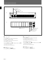
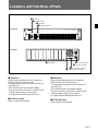
8 ~AC IN A connector
Front panel
Rear panel
6 U (signal ground) terminal
7 STATUS OUT connector
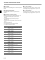
Locations and Functions of Parts
1 Indicator A
Lights in green when power unit A is turned on.
Flashes in red in the following cases:
•The temperature inside power unit has risen to a
specified level.
•The ventilation fans have stopped rotating.
•Only power unit B is turned on, or trouble occurs
with the output voltage of power unit A.
•A voltage load exceeds the specified level.
2 POWER A switch
Turns on and off power unit A.
5
Cover plates
3 Indicator B
2 POWER A switch
4 POWER B switch
1 Indicator A
9 ~AC IN B connector
3 Indicator B
Lights in green when power unit B is turned on.
Flashes in red in the following cases:
•The temperature inside power unit has risen to a
specified level.
•The ventilation fans have stopped rotating.
•Only power unit A is turned on, or trouble occurs
with the output voltage of power unit B.
•A voltage load exceeds the specified level.
4 POWER B switch
Turns on and off power unit B.

6 (E)
5 Cover plates
Remove the corresponding plates to install the optional
boards.
6 U (signal ground) terminal
For signal ground. Connect to a ground wire as
required.
7 STATUS OUT connector (15-pin)
Outputs the following error statuses of the PFV-L10.
•The inserted optional board does not function
correctly.
•The temperature inside the unit has risen to a
specified level.
•Trouble occurs with the output voltage of power unit
A or B.
•The power is turned off.
•The ventilation fans have stopped rotating.
•A voltage overload has occurred.
Pin No. Functions
1 Status output of the board inserted in slot 1.
Normal: Low level
2 Status output of the board inserted in slot 2.
Normal: Low level
3 Status output of the board inserted in slot 3.
Normal: Low level
4 Status output of the board inserted in slot 4.
Normal: Low level
5 Status output of the board inserted in slot 5.
Normal: Low level
6 Status output of the board inserted in slot 6.
Normal: Low level
7 Status output of the board inserted in slot 7.
Normal: Low level
8 Status output of the board inserted in slot 8.
Normal: Low level
9 Status output of the board inserted in slot 9
Normal: Low level
10 Status output of the power unit B.
Normal: Low level
11 Status output of the power unit A.
Normal: Low level
12 Status output of the ventilation fans.
Normal: Low level
13 Status output of the voltage load.
Normal: Low level
14 Status output of board inserted in slot 10
Normal: Low level
15 GND
8 ~AC IN A connector
To supply power to power unit A, connect to an AC
power supply using an appropriate AC power cord.
9 ~AC IN B connector
To supply power to power unit B, connect to an AC
power supply using an appropriate AC power cord.
Locations and Functions of Parts

7 (E)
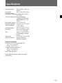
Specifications
Power requirements 100 to 120/220 to 240 V AC,
50/60 Hz
Current drain 100 V: 1.4 A, 240 V: 0.58 A
Peak inrush current
(1) Power ON, current probe method: 20 A (100 V),
25 A (240 V)
(2) Hot switching inrush current, measured in
accordance with European
standard EN55103-1: 18 A
(230 V)
Power supply capacity +5 V DC: max. 13 A
Operating temperature 5°C to 40°C (41°F to 104°F)
Storage temperature –20°C to +60°C
(–4°F to +140°F)
Operating humidity 30% to 70% (at 25°C/77°F)
Dimensions 440 × 88 × 353 mm (w/h/d)
(16
7
/8 × 3
1
/2 × 14 inches)
Mass Approx. 7.0 kg (15 lb 43 oz)
(not including the optional
boards)
Status output STATUS OUT: D-sub 15-pin
Supplied accessories Operation Manual (1)
Installation Manual (1)
Optional accessories
AC power cord (for USA and Canada only)
125 V, 10 A, 2.4 m (8 ft.)
Part No.: 1-557-377-11
AC power cord (for Europe only)
250 V, 10 A, 2.4 m (8 ft.)
Part No.: 1-782-929-21
RMM-10 Rack Mount Kit
Design and specifications are subject to change
without notice.


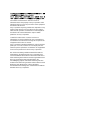
The material contained in this manual consists of
information that is the property of Sony Corporation and is
intended solely for use by the purchasers of the equipment
described in this manual.
Sony Corporation expressly prohibits the duplication of any
portion of this manual or the use thereof for any purpose
other than the operation or maintenance of the equipment
described in this manual without the express written
permission of Sony Corporation.
Le matériel contenu dans ce manuel consiste en
informations qui sont la propriété de Sony Corporation et
sont destinées exclusivement à l’usage des acquéreurs de
l’équipement décrit dans ce manuel.
Sony Corporation interdit formellement la copie de quelque
partie que ce soit de ce manuel ou son emploi pour tout
autre but que des opérations ou entretiens de l’équipement
à moins d’une permission écrite de Sony Corporation.
Das in dieser Anleitung enthaltene Material besteht aus
Informationen, die Eigentum der Sony Corporation sind,
und ausschließlich zum Gebrauch durch den Käufer der in
dieser Anleitung beschriebenen Ausrüstung bestimmt sind.
Die Sony Corporation untersagt ausdrücklich die
Vervielfältigung jeglicher Teile dieser Anleitung oder den
Gebrauch derselben für irgendeinen anderen Zweck als die
Bedienung oder Wartung der in dieser Anleitung
beschriebenen Ausrüstung ohne ausdrückliche schriftliche
Erlaubnis der Sony Corporation.

PFV-L10 (SY, , )
3-866-912-02(1)
Printed in Japan
2002.11.13
1999
Sony Corporation
B & P Company
-
 1
1
-
 2
2
-
 3
3
-
 4
4
-
 5
5
-
 6
6
-
 7
7
-
 8
8
-
 9
9
-
 10
10
-
 11
11
-
 12
12
-
 13
13
-
 14
14
-
 15
15
-
 16
16
-
 17
17
-
 18
18
-
 19
19
-
 20
20


Sony PFV-L10 Manuel utilisateur
- Taper
- Manuel utilisateur
- Ce manuel convient également à
dans d''autres langues
- English: Sony PFV-L10 User manual
- 日本語: Sony PFV-L10 ユーザーマニュアル
Documents connexes
-
Sony DVO-1000MD Manuel utilisateur
-
-
-
-
-
-
-
-
Sony Car Satellite TV System FWD-S55H2 Manuel utilisateur
-
Autres documents
-
Waeco MOBITRONIC RV-RMM-70 Le manuel du propriétaire
-
-
 Blackmagic Design Teranex Mini HDMI - SDI 12G Manuel utilisateur
-
LG LS42F Manuel utilisateur
-
Blackmagic Teranex Mini Manuel utilisateur
-
Blackmagic MC BiDirectional SDI/HDMI Manuel utilisateur
-
-
Yamaha EMB1D Le manuel du propriétaire
