


EN
The bolt of lightning in an equilateral triangle
warns the user that the device has high volt-
age that could result in a risk of electric shock.
Warning: To prevent any risk of electric shock,
do not remove the cover (or the back) from
the device. There are no user-serviceable
parts in this device. For maintenance or re-
pairs, contact a qualified professional.
The exclamation mark in an equilateral trian-
gle warns the user that the manual contains
important instructions on how to use and look
after the device.
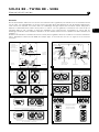
1. Read these instructions.
2. Keep these instructions.
3. Heed all the warnings.
4. Follow all the instructions.
5. Risk of electric shock. Do not open.
Do not submerge your product in water or
expose them to humidity.
6. Only clean with a dry cloth.
7. Do not obstruct ventilation openings.
Follow the manufacturer’s instructions for
installing the device. Leave a distance of at
least 5 cm around the product for proper ven-
tilation.
8. Do not install the device close to a heat
source such as a radiator, cooker, heat vents
or any other appliance (including amplifiers)
that gives out heat.
9. Follow the safety instructions for the
power supply cord. This product is a device
belonging to Class 1. Only plug in the device
using the mains plug provided, which incor-
porates an earth connection. The device must
be plugged into an earthed mains socket.
10. Make sure the power cable can’t be trod-
den on, crushed or pinched. Take particular
care with the plug and the cable connection
to the device.
11. Only use accessories recommended by
the manufacturer.
12. Only use handling equipment, stands, tri-
pods, mounts or tables recommended by the
manufacturer or sold with the device.
If using a trolley, take extra care when moving
the trolley and device together, to prevent the
device from falling o and causing injury.
13. Unplug the device during storms or long
periods when it is not in use.
14. All maintenance tasks should be per-
formed by a qualified professional. Mainte-
nance is required in case of any kind of dam-
age to the device (damaged cable or plug,
spillages or objects inserted into the device,
exposure to rain or humidity, if the device mal-
functions or overturns, etc.).
15. The product should only be connected to
the mains power type shown on the label on
the device. If you’re not sure what type of mains
electrical supply you have, ask your retailer or
your electricity supplier. For devices intended
for use with a battery or another power source,
see the user manual.
16. Do not use this device in tropical climates.
17. Do not use this device at altitudes of more
than 2,000 m.
18. Do not overload wall sockets, extension
leads or multiple socket outlets as this could
cause fire or electric shock.
19. Do not insert any objects into the device’s
ventilation openings. They could come into
contact with one of the high-voltage compo-
nents or short-circuit them and cause a fire or
electric shock. Do not spill liquid on the device.
20. Do not attempt to repair this device your-
self. Opening it may expose you to hazardous
voltages or to other risks. Contact a qualified
professional for all maintenance work.
21. When replacement components are
needed, make sure that the maintenance
technician uses the components recommend-
ed by the manufacturer or components with
the same technical features as the original
product. Using non-compliant components
could cause fires, electric shocks or other
risks.
22. After any maintenance or repair work on
the device, ask the maintenance technician to
test it to check that it works safely.
23. The appliance should only be mounted
on a wall or ceiling if the manufacturer allows
for this.
24. The On/O switch on the back of the de-
vice cuts o the mains power supply to the
device. The user should be able to access it at
all times.
25. To avoid damaging your hearing, do not
listen to loudspeakers at high volumes for
long periods of time.
Listening to speakers at high volumes can
cause damage to the user’s ears and may lead
to hearing problems (temporary or perma-
nent deafness, buzzing in the ears, tinnitus,
hyperacusis).
Exposure to excessive volumes (over 85dB)
for more than one hour can cause irreparable
damage to your hearing.
USA:
Federal Communication Commission Interference Statement
This device complies with Part 15 of the FCC Rules. Operation is subject to the following
two conditions: (1) This device may not cause harmful interference, and (2) this device
must accept any interference received, including interference that may cause undesired
operation.
This equipment has been tested and found to comply with the limits for a Class B digi-
tal device, pursuant to Part 15 of the FCC Rules. These limits are designed to provide
reasonable protection against harmful interference in a residential installation. However,
there is no guarantee that interference will not occur in a particular installation.
Canada:
Industry Canada Statement:
This device complies with ISED’s licence-exempt RSSs. Operation is subject to the fol-
lowing two conditions: (1) This device may not cause harmful interference, and (2) this
device must accept any interference received, including interference that may cause un-
desired operation.
Le présent appareil est conforme aux CNR d’ ISED applicables aux appareils radio
exempts de licence. L’exploitation est autorisée aux deux conditions suivantes : (1) le
dispositif ne doit pas produire de brouillage préjudiciable, et (2) ce dispositif doit ac-
cepter tout brouillage reçu, y compris un brouillage susceptible de provoquer un fonc-
tionnement indésirable.
(CEI 60417-6044)
An example of this equipment has been tested and found to comply with the following European directives and international standards:
Electromagnetic compatibility
EN 55103
EN 61000
Electrical safety
EN 60065
READ FIRST !
IMPORTANT SAFETY INSTRUCTIONS !
English

4
EN
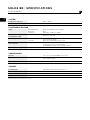
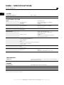
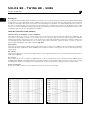
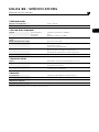
SOLO6 BE : SPECIFICATIONS
User manual
SYSTEM
Frequency response
40Hz - 40kHz
Maximum SPL
113dB SPL (peak @ 1m)
ELECTRONIC SECTION
Input
Type/Impedance
Connector
Sensitivity
Electronically balanced / 10 kOhms
XLR
Adjustable, +4dBu ou -10dBV
LF amplifier stage
HF amplifier stage
150W rms, BASH
®
technology
100W rms, class AB
Power supply
Main Voltage
Connection
230V (1.6A fuse rating)
115V (3.15A fuse rating)
IEC inlet and detachable power cord
User controls
Input level switch
LF and HF contours (potentiometers)
Power ON/OFF switch, mains voltage selector
Indicator
Power on LED
TRANSDUCERS
Woofer
"W" cone, Focal 6W4370B 6.5" drive unit
High frequency
Focal TB871 inverted Beryllium dome tweeter
with protective grille
Shielding
Integral through concellation magnets or by magnet design
CABINET
Construction
19mm MDF panels with internal braces
Finish
Real red veneer on sides
Dimensions (HxWxD)
330mm x 240mm x 290mm - (13"x9.5"x11.4")
Weight
11kg - (24.2lb)
All specifications are subject to change.

5
EN
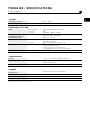
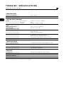
TWIN6 BE : SPECIFICATIONS
User manual
SYSTEM
Frequency response 40Hz - 40kHz
Maximum SPL 115dB SPL (peak @ 1m)
ELECTRONIC SECTION
Input
Type/Impedance
Connector
Sensitivity
Electronically balanced / 10 kOhms
XLR
Adjustable, +4dBu ou -10dBV
LF amplifier stage
LF/MF amplifier stage
HF amplifier stage
150W rms, BASH
®
technology
150W rms, BASH
®
technology
100W rms, class AB
Power supply
Main Voltage
Connection
230V (2A fuse rating)
115V (4A fuse rating)
IEC inlet and detachable power cord
User controls
Input level switch
Speaker (left/right) switch
LF and HF contours (potentiometers)
Power ON/OFF switch, mains voltage selector
Indicator
Power on LED
TRANSDUCERS
Woofer
2 x "W" cone, Focal 6W4370B 6.5" drive unit
High frequency
Focal TB871 inverted Beryllium dome tweeter
with protective grille
Shielding
Integral through concellation magnets or by magnet design
CABINET
Construction
19mm MDF panels with internal braces
Finish
Real red veneer on sides
Dimensions (HxWxD)
250mm x 500mm x 340mm (9.8" x 19.7"x 13.4")
Weight
14kg - (30.8lb)
All specifications are subject to change.

6
EN
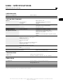
SUB6 : SPECIFICATIONS
User manual
All specifications are subject to change.
SYSTEM
Frequency response
30Hz - 250Hz
Maximum SPL
116dB SPL (peak @ 1m)
ELECTRONIC SECTION
Input
Type/Impedance
Connector
Sensitivity
Left, Right, LFE
Electronically balanced / 10kOhms
Female 3 pins XLR
Variable
Output (to satellites)
Type/Impedance
Connector
Left, Right
Electronically balanced / 50Ohms
Male 3 pins XLR
Amplifier
350 W rms, BASH
®
technology
Internal processing
and functions
Subwoofer section
Satellite section
Left + Right mono summation
LFE + lo-passed mono sum
24dB/octave variable lo-pass filter
Phase adjustment
Polarity
24dB/octave, defeatable hi-pass filters
with selectable frequency
User controls
Sub level (sensitivity) adjustment
Lo-pass frequency adjustment
Phase adjustment
Polarity switch
Mute
2.1 bypass (controlled by external footswitch)
Hi-pass frequency selection
Hi-pass defeat
Indicators (LED’s)
Power on
Mute
Hi-pass defeat
Power supply
Mains voltage
Connection
230V (T1.6AL fuse rating) or 115V (T3.15AL fuse
rating)
IEC inlet and detachable power cord
TRANSDUCERS
Subwoofer
“W” composite sandwich cone, high excursion Focal 11W7670,
270mm (10.6”) drive unit
CABINET
Construction
22mm MDF panels with internal braces
Finish
Real red veneer on sides - Black on body
Dimensions (HxWxD)
380mm x 344mm x 440mm (15” x 13.5”x 17.3”)
Weight
23kg (50.7lb)
Due to constant technological advances, Focal reserves its right to modify specifications without notice.
Images may not conform exactly to specific product.

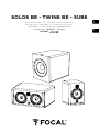
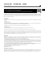
SOLO6 BE - TWIN6 BE - SUB6
User manual
7
EN
Thank you for purchasing a Focal product. Welcome to our High-Fidelity world. Innovation, tradition, excellence
and pleasure are our values; our one and only aim is to bring you a sound that is rich, pure and true. To get the
most out of your product, we recommend that you read the instructions in this booklet, then store it in a safe
place to refer to in the future.
Unpacking
In addition to one loudspeaker and a user manual (such as this one), each Solo6 Be or Twin6 Be carton should
contain:
• A power cord.
• A guarantee card.
• A plastic bag containing an information note “Beryllium inverted dome tweeter”, and some adhesive tape to
ax on the tweeter in the unlikely event of the dome being damaged.
In addition to one subwoofer and a user manual each Sub6 Be carton include:
• A power cord.
• A guarantee card.
• A grille protecting the drive unit (which it is advisable to remove whenever possible).
Please check that none of these items are missing, and remove all accessories from the carton.
To remove the loudspeaker from its carton without damage, open the end flaps fully and bend them right
back. Then remove the upper cushion and lift the loudspeaker out gently. Inspect the speaker for signs of any
possible damage.In the unlikely event of this having occurred please inform the carrier and supplier. It is a good
practice to keep the packaging in case of future transportation.
Beryllium
Solo6 Be and Twin6 Be use a tweeter with an inverted dome made from pure beryllium, with the capacity to
augment the bandwidth to 40 kHz. In its solid form, beryllium is harmless. However, given its nature, certain
precautions should be taken to avoid exposure to unnecessary risks:
• The beryllium dome must never come into contact with abrasive materials.
• If the beryllium dome is damaged in any way, you should cover up the entire surface area of the dome using
the protective adhesive strip supplied, as soon as possible. You will find the adhesive strip in the plastic packet
containing the leaflet for the tweeter with an inverted dome made from pure beryllium. Contact the retailer to
have the tweeter dismantled and replaced by trained personnel at the distributor.
• If the dome is broken, any beryllium particles should be carefully collected using sticky tape and then placed
in a hermetically sealed plastic bag and sent back to the retailer along with the loudspeaker.
For more information, please refer to the safe use manual in the box.
You can also address your questions directly to:
beryllium@focal.com
Conditions of warranty
All Focal loudspeakers are covered by warranty drawn up by the official Focal distributor in your country. Your
distributor can provide all details concerning the conditions of warranty. Warranty cover extends at least to
that granted by the legal warranty in force in the country where the original purchase invoice was issued.
Please validate your Focal-JMlab warranty,
it is now possible to register your product online: www.focal.com/warranty

SOLO6 BE - TWIN6 BE - SUB6
User manual
8
EN
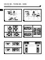
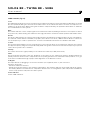
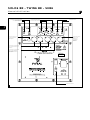
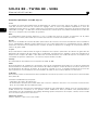
Input
sensitivity switch
D
B
Midrange
Midrange
E
A
Audio
input connector
Voltage selector
Fuse holder
HF control
LF control
Audio
input connector
Input sensitivity
Switch
Midrange driver
selector
Voltage selector
Fuse holder
HF control
LF control
Position A
Left/Right
Position B
Left/Right
Position C
Left
Position C
Right
Position A
Left/Right
Position B
Left
Position C
Left
Right
Driver choosen to reproduce midrange when switch selected for left speaker
Driver choosen to reproduce midrange when switch selected for right speaker
Left/Right
Right
F
C
Recommended choice for
midrange driver positionning.
Midrange driver on the inside.

SOLO6 BE - TWIN6 BE - SUB6
User manual
9
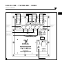
EN
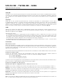
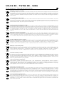
Hi Pass switch
Defeat switch
Phase control
Level control
Lo Pass control
Polarity switch
Mute switch
Voltage selector
Audio intput connectors
(Stereo/2.1 wiring only)
Audio output connectors
to satellites speakers
(Stereo/2.1 wiring only)
LFE input connector
(mutichannel
wiring only)
G
6.35 Jack connector
for 2.1 Bypass
footswitch
remote control

SOLO6 BE - TWIN6 BE - SUB6
User manual
10
EN
Solo6 Be
Solo6 Be is a two-way active loudspeaker (2 internal amplifiers channels), comprising one “W” cone 6.5” low/
mid unit, loaded with a large cross-section laminar port, and an inverted pure Beryllium dome (fig. A).
Twin6 Be
Twin6 Be is a three-way active loudspeaker (3 internal amplifiers channels), comprising two “W” cone 6.5” low/
mid units, loaded with two large cross-section laminar ports, and an inverted pure Beryllium dome. The two
6.5” drive units operate at low frequencies but only one of them (either can be selected) will reproduce the
midrange (fig. B).
Sub6
Sub6 is an active subwoofer (1 integral amplifier) designed for professional monitoring systems. It uses a 11”
drive unit equipped with a “W” composite cone, and loaded by a large cross-section laminar port (fig. G).
Sub6 may be used :
- For bass or sub-bass enhancement in stereo + sub setups (2.1 or 2.2). The rear panel of Sub6 allows for the
connection of a traditional stereo source (Left In / Right In), while providing hi-passed outputs intended to
feed the main speakers (satellites),
- As a LFE channel (Low Frequency Eects) in a multi-channel installation (5.1, 5.2, 6.1…), via a dedicated input
of the rear panel.
Installing
Mains voltage
After having unpacked the unit, first check that the operating voltage is correctly set (see location on rear
panel). If it is not, adjust the selector to the appropriate position. Also check and if necessary replace the fuse,
which rating depends on the operating voltage (please refer to technical specifications).
Solo6 and Twin6 must be earthed using the power cord supplied.
Audio connections: general
The audio signal is to connect to the XLR inlet. This is a balanced input, which use the standard cabling scheme,
namely:
Pin 1 = Ground (shield)
Pin 2 = In phase voltage (“hot”)
Pin 3 = Out-of-phase voltage (“cold”)
If the audio source is unbalanced, common practice is to link “cold” and ground pins (pins 3 and 1 respectively).
This is generally achieved within the cable.
Audio connections: Sub6 (fig. G)
Stereo + Sub setup (2.1 or 2.2):
Left IN: this input is intented to receive the signal coming from the left channel of your source (mixing console,
or other…).
Right IN: this input is intented to receive the signal coming from the right channel of your source (mixing
console, or other…).
Left OUT: this output is intended to connect to the left main loudspeaker of your system. The signal supplied
by this output is internally processed through a high pass filter.
Right OUT: this output is intended to connect to the right main loudspeaker of your system. The signal supplied
by this output is internally processed through a high pass filter.
Multichannel configuration: LFE: this input is intended to feed your Sub6 in a multichannel application (5.1, 5.2,
6.1, …): this channel is dedicated to low frequencies only.

SOLO6 BE - TWIN6 BE - SUB6
User manual
11
EN
Positioning
Solo6 Be and Twin6 Be are designed for near field monitoring and should be placed at a distance between 1
and 3 metres from the listener, pointing towards the listening position. They can be sitting on the console top
or placed on appropriate stands. In any way it is recommended that the tweeter is at a height from the floor
approximately equivalent to that of the listener’s ears. If required it can make sense to place the speakers
upside down so that the previous rule is better fulfilled (fig. C,D).
Solo6 Be could be used vertically or horizontally depending on the environment, preferably pointing towards
the listener (fig. C).
By design Twin6 Be’s are rather intended for a landcape orientation, though in some situations they could be
positioned vertically. As seen in the earlier rear panel description, Twin6 Be has a switch allowing to choose
which drive unit is to reproduce the mid frequencies (see below) (fig. E). Consequently it will always be
possible, as desirable, to configure the speakers in a “mirror” (ie symetrical) way (fig. F). As a general rule
having the “midrange” driver on the inside of the cabinet results in better imaging.
Optimal positioning of Sub6 may vary depending on the surface, the shape and acoustic properties of the
listening room. You are advised to try various locations so to choose the one giving the best possible and most
level sound balance. As a rule of thumb the optimal location will often be in a corner of the room.

SOLO6 BE - TWIN6 BE - SUB6
User manual
12
EN
Running in
As in all brand new loudspeaker the drivers need some run in period: they are mechanical elements demanding
a little time to settle and adapt to the climatic environment. This period will vary depending of the working
conditions and may take up to a few weeks. Avoid pushing the speakers very hard during their first hours of
use, but to accelerate the run-in process it is good practice to operate the speakers at moderate levels for 20
hours or so, with programmes having significant low frequency content. Only once the transducers have come
to stabilize will you get the optimum performance.
Solo6 Be/Twin6 Be/Sub6 Controls
Speaker switch (Left/Right) : only for Twin6 Be
This switch allows the user to select which one of the two 6.5” drivers will reproduce the midrange. By
convention, the “Right” position of the switch will select the left hand side driver (when facing the cabinet
laying horizontally). Conversely in the “Left” position the right hand side driver (facing the cabinet) will be the
one operating in the mid frequencies. It is easy to figure how useful this control is when it comes to get the
best possible imaging in any cabinet layout (fig. E,F).
Input switch
The input sensitivity can be adjusted using this two position switch. The +4dBu position is suitable for standard
professional audio equipment, while -10dBV position may be used for other types of sources providing a lesser
output level.
HF contour
This control allows for a continuous adjustement of the high frequency level; it operates above 5kHz within a
±3dB range (fig. H).
LF contour
This control allows for a continuous adjustement of the low frequency level; it operates below 150Hz within
a ±6dB range (fig. I). This adjustement is typically useful to deal with possible excessive level of LF energy
resulting from acoustic coupling associated with close reflecting surfaces: mixing console, nearby walls…
Power on indicator
A power on LED is located on the cabinet front panel, near the Focal logo.
H
I

SOLO6 BE - TWIN6 BE - SUB6
User manual
13
EN
Sub6 controls (fig. G)
Level
This adjustement allows to set the sound level of the subwoofer relative to that of the main loudspeakers. It should
also be optimised taking into account the actual location of the subwoofer and its acoustic consequences: for
example in an angle the 6 dB acoustic gain should be compensated by an equivalent attenuation to maintain
the overall balance of the system.
Mute
This switch will turn out the output signal of the subwoofer channel (making it silent does not require to switch
the power off). When muting the subwoofer the high pass filters used for the main speakers will remain active.
Hi Pass
This area is dedicated to the setting of the high pass filters intended for the main speakers in a 2.1 configuration.
The “Defeat” switch allows to disable (ie by-pass) these filters. The 75 Hz / 100 Hz switch allows to select the
cut-off frequency, in order to optimise the acoustic recombination between the satellites and Sub6.
Lo Pass
This potentiometer adjusts the cut-off frequency of the low pass filter on the subwoofer channel, thus setting
the upper frequency range to be reproduced by Sub6. The goal is to achieve the smoothest frequency response
of the whole system: sub + satellites.
Polarity
This switch inverts the signal polarity on the subwoofer channel (ie 180° phase shift).
Phase
This potentiomer provides some fine ajustment of the phase on the subwoofer channel. Combined with the
polarity switch it can be used to compensate for the spacing between the sub and the main speakers, so to get
a coherent soundfield through a proper time alignment of the different sources.
2.1 Bypass
This input allows for plugging in a control footswitch (not supplied) via a ¼” jack connector.
Turning it active will :
- mute the subwoofer channel
- defeat the high pass filters in the satellites signal paths. The satellites will then be fed with full range signals.
This facility allows for instantaneous comparison between the 2.1 configuration (with sub) and the traditional
stereo setup (without sub) with the same system.
Power indicator
Power "LED" indicator.

FR
L’éclair représenté par le symbole flèche
et contenu dans un triangle équilatéral,
a pour objet de prévenir l’utilisateur de
la présence de tension élevée au sein de
l’appareil pouvant entraîner un risque de choc
électrique.
Attention : Afin de prévenir tout risque de
choc électrique, n’enlevez pas le capot (ou
l’arrière) de cet appareil. Aucune pièce n’est
remplaçable par l’utilisateur. Pour entretien ou
réparation, contactez une personne qualifiée.
Le point d’exclamation contenu dans un
triangle équilatéral, a pour objet de prévenir
l’utilisateur de la présence d’instructions
importantes mentionnées dans le mode
d’emploi et relatives à la mise en oeuvre et à
l’entretien de l’appareil.
1. Lisez ces instructions.
2. Conservez ces instructions.
3. Prenez en considération les mises en garde.
4. Suivez toutes les instructions.
5. Risque de choc électrique. Ne pas ouvrir.
Ne pas exposer à l’eau ou à l’humidité.
6. Nettoyez uniquement avec un chion sec.
7. N’obstruez aucun orifice de ventilation.
Installez l’appareil en suivant les instructions
du fabricant. Laissez une distance de 5 cm
minimum autour du produit pour une bonne
ventilation.
8. N’installez pas l’appareil à proximité d’une
source de chaleur tel un radiateur, une
cuisinière, une bouche de chauage ou tout
autre appareil (y compris les amplificateurs)
dissipant de la chaleur.
9. Respectez les instructions de sécurité
concernant le cordon d’alimentation secteur.
Ce produit appartient aux appareils de
Classe1. Connectez l’appareil uniquement à
l’aide de la fiche secteur fournie intégrant une
liaison à la terre. L’appareil doit être raccordé
à une prise secteur dotée d’une protection
par mise à la terre.
10. Assurez-vous que le câble d’alimentation
ne puisse pas être piétiné, écrasé ou pincé.
Une attention toute particulière doit être
accordée à la fiche d’alimentation et à la
liaison du cordon avec l’appareil.
11. N’utilisez que les accessoires recommandés
par le fabricant.
12. N’utilisez que les appareils de manutention,
pieds, trépieds, supports ou tables
recommandés par le fabricant ou ceux vendus
avec l’appareil.
Lorsqu’un chariot est utilisé, redoublez de
prudence lors du déplacement de l’ensemble
chariot/appareil afin d’éviter toutes blessures
par basculement.
13. Débranchez l’appareil en cas d’orage ou
pendant de longues périodes pendant lequel
l’appareil n’est pas utilisé.
14. Toute tâche de maintenance doit être
réalisée par un personnel qualifié. Une
maintenance est nécessaire à la suite de
tout dommage occasionné à l’appareil tels
que la détérioration du câble ou de la fiche
d’alimentation, le déversement de liquide ou
l’insertion d’objets à l’intérieur de l’appareil,
l’exposition à la pluie ou à l’humidité, le
mauvais fonctionnement ou le renversement
de l’appareil.
15. Ce produit doit être raccordé uniquement
au type d’alimentation secteur indiqué sur
l’étiquette figurant sur l’appareil. En cas
d’hésitation sur le type d’alimentation de
votre installation électrique, consultez le
vendeur de votre produit ou votre fournisseur
d’électricité. Pour les appareils prévus pour
une utilisation à partir d’une batterie ou d’une
autre source d’alimentation, se référer au
manuel d’utilisation.
16. N’utilisez pas cet appareil dans des climats
tropicaux.
17. N’utilisez pas cet appareil dans des zones
situées au-dessus de 2000m d’altitude.
18. Ne surchargez pas les prises murales, les
rallonges électriques ou les prises multiples.
Il pourrait en résulter incendies ou chocs
électriques.
19. N’insérez jamais un quelconque objet par
les trous de ventilation de l’appareil. Il pourrait
entrer en contact avec des composants
soumis à de hautes tensions ou les court-
circuiter et ainsi occasionner un incendie ou
un choc électrique. Ne répandez jamais de
liquide sur l’appareil.
20. Ne tentez pas de réparer cet appareil
par vos propres moyens; l’ouverture de cet
appareil peut vous exposer à des tensions
dangereuses ou à d’autres risques. Pour toute
intervention de maintenance, adressez-vous à
un personnel qualifié.
21. Lorsque le remplacement de composants
est nécessaire, assurez-vous que le technicien
de maintenance utilise les composants
spécifiés par le fabricant ou présentant
des caractéristiques identiques à ceux
correspondant à l’exemplaire d’origine.
Des composants non conformes peuvent
provoquer incendies, chocs électriques ou
autres risques.
22. Après toute intervention ou réparation
sur l’appareil, demandez au technicien de
maintenance de procéder à des tests afin de
vérifier que le produit fonctionne en toute
sécurité.
23. L’appareil ne doit être monté sur un mur ou
au plafond que si le constructeur le prévoit.
24. Le commutateur On/O situé à l’arrière
du produit est le dispositif de sectionnement
de l’alimentation. Il permet de déconnecter
l’électronique du secteur. Il doit toujours rester
accessible pour l’utilisateur.
25. Afin d’éviter des dommages auditifs
éventuels, n’écoutez pas les enceintes à un
niveau sonore élevé pendant une longue durée.
L’écoute d’enceintes à forte puissance
peut endommager l’oreille de l’utilisateur
et entraîner des troubles auditifs (surdité
temporaire ou définitive, bourdonnements
d’oreille, acouphènes, hyperacousie).
L’exposition des oreilles à un volume excessif
(supérieur à 85dB) pendant plus d’une heure
peut endommager l’ouïe irréversiblement.
(CEI 60417-6044)
Un échantillon de ce produit a été testé et déclaré en conformité avec les directives européennes et autres normes internationales suivantes :
Compatibilité électromagnétique
EN 55103
EN 61000
Sécurité électrique
EN 60065
À LIRE EN PREMIER !
INSTRUCTIONS DE SÉCURITÉ IMPORTANTES !
Français

15
FR
SOLO6 BE : SPÉCIFICATIONS
Manuel d'utilisation
PERFORMANCES
Réponse en fréquence
40 Hz - 40 kHz
Niveau SPL max
113 dB SPL (crête à 1m)
SECTION ELECTRONIQUE
Entrée
Type/Impedance
Connecteur
Sensibilité
Symétrie électronique / 10 kOhms
XLR
Ajustable, +4 dBu ou -10 dBV
Etage d’amplification
grave
Etage d’amplification aigü
150 W rms, technologie BASH
®
100 W rms, classe AB
Alimentation électrique
Tension secteur
230 V (fusible 1,6 A)
115 V (fusible 3,15 A)
Cordon secteur CEI amovible
Contrôles utilisateurs
Commutateur de niveau d’entrée
Niveaux de grave et d’aigü (potentiomètres)
Commutateur marche/arrêt, sélecteur de tension
Indicateur
DEL mise sous tension
TRANSDUCTEURS
Grave
Haut-parleur Focal 16,5 cm 6W4370B à cône "W"
Aigü
Tweeter Focal TB871 à dôme inversé en Béryllium pur
avec grille de protection
Blindage magnétique
Intégré, par utilisation de ferrite de blindage
ou construction magnétique
ENCEINTE
Construction
Panneaux 19 mm MDF avec renforts internes
Finition
Placage naturel rouge foncé sur les joues
Dimensions (HxLxP)
330 mm x 240 mm x 290 mm
Poids
11 kg
Toutes les caractéristiques sont susceptibles d’être modifiées

16
FR
TWIN6 BE : SPÉCIFICATIONS
Manuel d'utilisation
PERFORMANCES
Réponse en fréquence
40 Hz - 40 kHz
Niveau SPL max
115 dB SPL (crête à 1m)
SECTION ELECTRONIQUE
Entrée
Type/Impedance
Connecteur
Sensibilité
Symétrie électronique / 10 kOhms
XLR
Ajustable, +4 dBu ou -10 dBV
Etage d’amplification
grave
Etage d’amplification
grave/médium
Etage d’amplification aigü
150 W rms, technologie BASH
®
150 W rms, technologie BASH
®
100 W rms, classe AB
Alimentation électrique Tension secteur
230 V (fusible 2 A)
115 V (fusible 4 A)
Cordon secteur CEI amovible
Contrôles utilisateurs
Commutateur de niveau d’entrée
Commutateur enceinte gauche/droite
Niveaux de grave et d’aigü (potentiomètres)
Commutateur marchez/arrêt, sélecteur de tension
Indicateur
DEL mise sous tension
TRANSDUCTEURS
Grave et grave/médium
2 haut-parleurs Focal 16,5 cm 6W4370B à cône "W"
Aigü
Tweeter Focal TB871 à dôme inversé en Béryllium pur
avec grille de protection
Blindage magnétique
Intégré, par utilisation de ferrite de blindage
ou construction magnétique
ENCEINTE
Construction
Panneaux 19 mm MDF avec renforts internes
Finition
Placage naturel rouge foncé sur les joues
Dimensions (HxLxP)
250 mm x 500 mm x 340 mm
Poids
14 kg
Toutes les caractéristiques sont susceptibles d’être modifiées

17
FR
SUB6 : SPÉCIFICATIONS
Manuel d'utilisation
PERFORMANCES
Réponse en fréquence
30 Hz - 250 Hz
Niveau SPL maximum
116 dB SPL (pic à 1m)
SECTION ÉLECTRONIQUE
Entrées
Type/impédance
Connecteurs
Sensibilité
Gauche, Droite, LFE
Symétrique électronique/10 kOhms
XLR femelle 3 points
Variable
Sorties (vers satellites)
Type/Impedance
Connecteur
Sommation mono Gauche + Droite
Symétrique électronique/50 Ohms
XLR mâle 3 points
Amplification
350 W rms, technologie BASH
®
Traitement interne
du signal et fonctions
Section subwoofer Sommation mono Gauche + Droite
Sommation mono passe-bas + LFE
Filtre passe-bas réglable, 24 dB/octave
Ajustement de la phase
Polarité
Filtre passe-haut débrayable et réglable, 24 dB/
octave
Contrôles utilisateur
Réglage du niveau (sensibilité) du subwoofer
Réglage de la fréquence de coupure
du filtre passe-bas
Ajustement de la phase
Inverseur de polarité
Mute
Bypass 2.1 (contrôlé par une pédale externe)
Sélection de la fréquence de coupure
du filtre passe-haut
Désactivation du filtre passe-haut
Témoins lumineux (LED)
Marche
Mute
Filtre passe-haut débrayé
Alimentation eléctrique
Tension secteur
Connexion
230 V (fusible 1,6 A) ou 115 V (fusible 3,15 A)
Cordon secteur CEI amovible
TRANSDUCTEUR
Subwoofer
Focal 27 cm à longue excursion,
membrane sandwich composite "W", réf. : 11W7670
Toutes les caractéristiques sont susceptibles d’être modifiées
ÉBÉNISTERIE
Construction
Panneau MDF 22 mm avec renforts internes
Finition
Panneaux latéraux en bois massif teinté rouge
Placage plateaux noir
Dimensions (H x L x P)
380 mm x 344 mm x 440 mm
Poids
23 kg
Dans un but d'évolution, Focal-JMlab se réserve le droit de modifier les spécifications techniques de ses produits sans préavis.
Images non contractuelles.

SOLO6 BE - TWIN6 BE - SUB6
Manuel d'utilisation
18
FR
Vous venez d’acquérir un produit Focal et nous vous en remercions. Bienvenue dans notre univers, celui de la
Haute-Fidélité. Innovation, tradition, excellence et plaisir sont nos valeurs ; notre seul objectif est de vous offrir
un son pur, fidèle et riche. Afin d’exploiter toutes les performances de votre produit, nous vous conseillons de
lire les instructions de ce livret puis de le conserver soigneusement pour vous y référer ultérieurement.
Déballage
Une enceinte Solo6 Be ou Twin6 Be est livrée accompagnée des éléments suivants (outre le présent manuel) :
• Un cordon d’alimentation.
• Une carte de garantie.
• Un sachet plastique contenant une notice (Tweeter à dôme inversé en Béryllium), ainsi qu’une bande adhésive
à apposer sur le tweeter en cas d’endommagement du dôme.
Un caisson de grave Sub6 est livré accompagné des éléments suivants (outre le présent manuel) :
• Un cordon d’alimentation.
• Une carte de garantie.
• Une grille protectrice pour le subwoofer à membrane "W" (notre conseil est de l’enlever pour l’écoute dès
qu’il le sera possible).
Vérifiez qu’aucun de ces éléments ne manque, et enlevez tous les accessoires du carton.
Afin de ne pas endommager vos produits lors de leur déballage, veuillez respecter les étapes suivantes : ouvrez
complètement les volets du carton. Repliez les côtés. Ôtez la protection supérieure. Soulevez l’enceinte ou le
caisson précautionneusement. Vérifiez que l’emballage ne présente aucun signe de détérioration. Si toutefois
il était endommagé, prévenez le transporteur et le fournisseur. Il est important que l’emballage soit gardé en
bon état pour d’éventuelles utilisations futures.
Béryllium
Solo6 Be et Twin6 Be utilisent un tweeter à dôme inversé en Béryllium pur, capable d’étendre la bande passante
à plus de 40 kHz. Sous sa forme solide, ce matériau est inoffensif. Toutefois, par sa nature, certaines précautions
doivent être appliquées pour ne pas s’exposer à des risques inutiles :
• Le dôme en Béryllium ne doit jamais être mis au contact d’une matière abrasive.
• Si le dôme en Béryllium est endommagé sous quelle que forme que ce soit, il est nécessaire de le recouvrir
dès que possible sur toute sa surface par la bande adhésive de protection fournie. Vous la trouverez dans le
sachet plastique contenant la notice dédiée au tweeter à dôme inversé en Béryllium pur. Prendre contact avec
le revendeur afin de démonter et de remplacer le tweeter auprès d’un service compétent chez le distributeur.
• Si le dôme est brisé, les particules éventuelles de Béryllium doivent être récupérées avec soin au moyen
d’un ruban adhésif, puis être placées dans un sac plastique hermétiquement clos, à retourner au revendeur en
même temps que l’enceinte.
Pour de plus amples informations, veuillez vous référer au manuel de précaution d’emploi présent dans
l’emballage.
Vous pouvez également poser vos questions directement à l’adresse suivante :
beryllium@focal.com
Pour validation de la garantie Focal-JMlab,
il est maintenant possible d’enregistrer son produit en ligne : www.focal.com/garantie

SOLO6 BE - TWIN6 BE - SUB6
Manuel d'utilisation
19
FR
A
Interrupteur de
sensibilité d'entrée
Connecteur
d'entrée du
signal audio
Sélecteur
de tension
Porte fusible
Contrôle des
hautes fréquences
Contrôle des
basses fréquences
B
Connecteur
d'entrée du
signal audio
Interrupteur de
sensibilité
d'entrée
Interrupteur de
selection du haut-
parleur médium
Selecteur
de tensionPorte fusible
Contrôle des
hautes fréquences
Contrôle des
basses fréquences
D
Position A
Gauche/Droite
Position B
Position C
Gauche
Droite
Gauche/Droite
Position A
Gauche / Droite
Position B
Gauche / Droite
Position C
Gauche
Position C
Droite
C
Gauche
Choix conseillé pour le positionnement
du haut-parleur médium.
Haut-parleur médium
positionné à l'intérieur.
Droite
F
Midrange
Midrange
E
Haut-parleur choisi pour reproduire les médiums avec le switch sur
"enceinte gauche" (left speaker)
Haut-parleur choisi pour reproduire les médiums avec le switch
sur "enceinte droite" (right speaker)
Garantie
En cas de problème, adressez-vous à votre revendeur Focal. La garantie pour la France sur tout matériel Focal
est de 2 ans, non transmissible en cas de revente, à partir de la date d’achat. En cas de matériel défectueux,
celui-ci doit être expédié à vos frais, dans son emballage d’origine auprès du revendeur, lequel analysera le
matériel et déterminera la nature de la panne. Si celui-ci est sous garantie, le matériel vous sera rendu ou
remplacé. Dans le cas contraire, un devis de réparation vous sera proposé. La garantie ne couvre pas les
dommages résultant d’une mauvaise utilisation ou d’un branchement incorrect (bobines mobiles brûlées par
exemple...).
En dehors de la France, le matériel Focal est couvert par une garantie dont les conditions sont fixées localement
par le distributeur officiel Focal-JMlab de chaque pays, en accord avec les lois en vigueur sur le territoire
concerné.

SOLO6 BE - TWIN6 BE - SUB6
Manuel d'utilisation
20
FR
Connecteurs d’entrées audio
(pour système stéréo/2.1 uni-
quement)
Connecteurs de sorties audio
vers enceintes satellites
(pour système stéréo/2.1
uniquement)
Commutateur du filtre passe-haut
Interrupteur marche/arrêt
du filtre passe-haut
Contrôle de la phase
Contrôle du niveau sonore
Contrôle du filtre passe-bas
Inverseur de polarité
Interrupteur mute
Sélecteur de tension
Connecteur Jack 6.35
pour télécommande
du 2.1 Bypass
Connecteur d'entrée
LFE (pour une
utilisation en
configuration
multicanal :
5.1, 5.2...)
G
La page est en cours de chargement...
La page est en cours de chargement...
La page est en cours de chargement...
La page est en cours de chargement...
La page est en cours de chargement...
La page est en cours de chargement...
La page est en cours de chargement...
La page est en cours de chargement...
-
 1
1
-
 2
2
-
 3
3
-
 4
4
-
 5
5
-
 6
6
-
 7
7
-
 8
8
-
 9
9
-
 10
10
-
 11
11
-
 12
12
-
 13
13
-
 14
14
-
 15
15
-
 16
16
-
 17
17
-
 18
18
-
 19
19
-
 20
20
-
 21
21
-
 22
22
-
 23
23
-
 24
24
-
 25
25
-
 26
26
-
 27
27
-
 28
28


Focal Solo6 Be Manuel utilisateur
- Catégorie
- Subwoofers
- Taper
- Manuel utilisateur
dans d''autres langues
- English: Focal Solo6 Be User manual
Documents connexes
-
Focal Solo6 Be Manuel utilisateur
-
-
Focal Sub One Manuel utilisateur
-
Focal Alpha 80 Product information
-
Focal DOME2.1/DR Fiche technique
-
-
Focal Solo6 Manuel utilisateur
-
-
Focal CMS 50 Le manuel du propriétaire
-
Focal Solo 6 Manuel utilisateur
