Muskoka MTVSC2513SBP Assembly Instructions Manual
- Taper
- Assembly Instructions Manual

MTVSC2513SBP
Assembly Instructions
Instructions d’assemblage
Instrucciones de montaje
04/11
save These InsTrucTIons
conserver ces InsTrucTIons
guarde esTas InsTruccIones
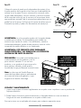
Electric Fireplace
Electric fireplace mantel with
a striking curved firebox insert
Foyer Électrique
Mantel à foyer électrique avec
un magnifique foyer courbé
Chimenea Eléctrica
Mueble de Chimenea eléctrica con una
sorprendente caja de fuego semicircular
11
YEAR
AN
AÑO
I
N
H
O
M
E
W
A
R
R
A
N
T
Y
G
A
R
A
N
T
I
E
À
L
A
M
A
I
S
O
N
G
A
R
A
N
T
Í
A
E
N
S
U
P
R
O
P
I
A
C
A
S
A

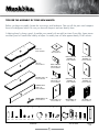
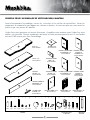
TIPS FOR THE ASSEMBLY OF YOUR NEW MANTEL
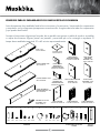
Before you begin assembly, locate the instructions and hardware. Take out all the parts and compare
them to the diagrams below. Be sure you have all the parts and can identify them.
A helping hand is always good. Assemble your mantel with an adult assistant if possible. Some pieces
are heavy and will need to be held by a helper. Assembly time will take approximately 30-60 minutes.
1
ANTI-TIP DEVICE HARDWARE TOUCH UP
PEN
BASE 1 PC
ZZ.2513SCN.01
T
OP 1 PC
ZZ.2513SCN.11
SHE
LF 2 PCS
ZZ.2513SCN.14
R
IGHT STORAGE
SIDE PANEL 1 PC
ZZ.2513SCN.06
L
EFT STORAGE
SIDE PANEL 1 PC
ZZ.2513SCN.07
R
IGHT SIDE PANEL
EXTERIOR 1 PC
ZZ.2513SCN.02
L
EFT SIDE PANEL
EXTERIOR 1 PC
ZZ.2513SCN.03
BACK PANEL 2 PCS
ZZ.2513SCN.10
R
IGHT SIDE PANEL
INTERIOR 1 PC
ZZ.2513SCN.04
R
IGHT DOOR 1 PC
ZZ.2513SCN.12
L
EFT SIDE PANEL
INTERIOR 1 PC
ZZ.2513SCN.05
L
EFT DOOR 1 PC
ZZ.2513SCN.13
F
IREBOX BRACE 1 PC
ZZ.2513SCN.15
CENTRAL SHELF 1 PC
ZZ.2513SCN.08
ST
ORAGE BACK
PANEL 1 PC
ZZ.2513SCN.09
a d e f
8 PCS
g
1 PC
b c
1 PCS 2 PCS 2 PCS 2 PCS2 PCS
8 PCS2 PCS2 PCS44 PCS8 PCS16 PCS16 PCS8 PCS8 PCS24 PCS
2 PCS
h i J k l
1
11
8
9
15
10
7
6
14
2 3
4 5
12 13
m n o p q

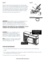
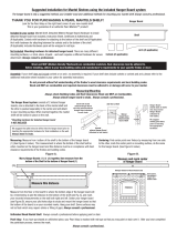
GET READY TO START
Before assembly, use scissors to unwrap the parts from the packaging.
DO NOT use a box cutter or exacto-knife as you may cut into the
mantel pieces inside the box and damage the finish. Check for the
hardware bag which is RED and located inside the packaging, taped
to the top box. Be sure you DO NOT discard any pieces.
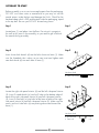
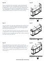
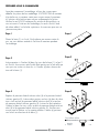
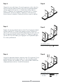
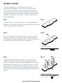
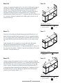
Step 1
Locate base (1) and place it on the floor. Do not put it up against
the wall at this point in the assembly, as you need to get in behind
the mantel during assembly.
Step 2
Insert 4 cam lock dowels (d) into the holes shown on base (1). Make
sure the threaded side is down so you can insert and tighten each
cam lock dowel (d) into each hole in base (1).
Step 3
Locate the right side panel interior (4) and the left side panel interior
(5). Insert 2 wood dowels (a) into the 2 holes at the bottom edge of
each of the right side panel interior (4) and left side panel interior
(5). Insert 2 cam locks (e) into holes at the base of each of the right
side panel interior (4) and left side panel interior (5). Make sure the
arrows on the 4 cam locks (e) are pointing downward toward the
base (1).
2
Step 1
Step 2
Step 3
Hardware Used
d Cam
Lock Dowels x 4
Hardware Used
a W
ood Dowel x 4
e Cam
Lock x 4
1
1
d
1
5
4
e
a
a

3
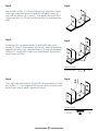
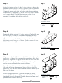
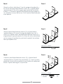
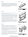
Step 4
Line up holes in base (1) with wood dowels (a), and holes in each
of the right side panel interior (4) and left side panel interior (5)
with cam lock dowels (d) in base (1). Push panels down until flush.
Tighten cam locks (e). Do not strip the cam locks by overtightening
them.
Step 5
Locate the right side panel exterior (2) and the left side panel
exterior (3). Insert 2 wood dowels (a) into the 2 holes at the bottom
edge of each of the right side panel exterior (2) and left side panel
exterior (3). Line up holes in base with wood dowels (a) and push
panels down until flush.
Step 6
Once right side panel exterior (2) and left side panel exterior (3) are
flush to base (1), insert large bolt (b) through washer (c) and into the
base of each exterior panel. Tighten until secure.
Step 4
Step 5
Step 6
Hardware Used
a W
ood Dowel x 4
Hardware Used
b L
arge Bolt x 4
c W
asher x 4
1
5
4
1
2
3
a
b
c
1
2
3

4
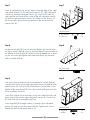
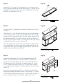
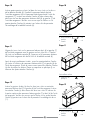
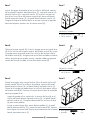
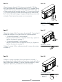
Step 7
Insert 8 wood dowels (a) into the holes on the top edge of the right
side panel exterior (2), left side panel exterior (3), right side panel
interior (4), and left side panel interior (5). Insert 4 cam locks (e)
into the holes on the top of the inside of the left side panel interior
(5) and the right side panel interior (4). Make sure the arrows on
the 4 cam locks (e) are pointing upwards to be joined with the
central shelf (8).
Step 8
Locate central shelf (8). Insert 4 cam lock dowels (d) into the holes
on top of central shelf (8). Insert 4 cam lock dowels into the holes on
the bottom of central shelf (8). Make sure the threaded side is down
so you can insert and tighten each cam lock dowel (d) into each
hole in central shelf (8).
Step 9
Line up the cam lock dowels (d) on the bottom of central shelf (8)
with the holes at the top of right side panel interior (4) and left side
panel interior (5). Line up the 8 wood dowels with the holes in the
bottom of the central shelf (8). Press the central shelf down onto the
lower assembly until flush.
Once flush, tighten the 4 cam locks (e) on the inside of the left side
panel interior (5) and the right side panel interior (4). Do not strip
the cam locks (e) by overtightening them.
Inser
t large bolt (b) through washer (c) through right side panel
exterior (2) and up into the central shelf (8). Tighten until secure.
Repeat for the left side panel exterior (3).
Step 7
Step 8
Step 9
Hardware Used
a W
ood Dowel x 8
e Cam
Lock x 4
Hardware Used
b L
arge Bolt x 4
c W
asher x 4
1
2
3
5
4
a
a
e
8
Hardware Used
d Cam
Lock Dowels x 8
d
d
8
1
2
3
5
4
b
c

Hardware Used
a W
ood Dowel x 4
e Cam
Lock x 4
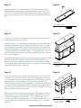
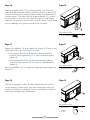
Step 10
Place 4 wood dowels (a) into the holes on the top of the central
shelf (8). Locate the right side storage panel (6) and the left side
storage panel (7). Insert 2 cam locks (e) into the 2 bottom holes on
the inside of each of the right side storage panel (6) and the left
side storage panel (7). Make sure the arrows on the 4 cam locks (e)
are pointing downward to be joined with the central shelf (8).
Step 11
Line up the holes in the right side storage panel (6) and the left side
storage panel (7) with the wood dowels (a) and cam lock dowels
(d) in the central shelf (8). Press down on the side storage panels
until secure with central shelf (8).
Once flush, tighten the 4 cam locks (e) on the inside of the left side
storage panel (7) and the right side storage panel (6). Do not strip
the cam locks (e) by overtightening them. Place 1 plastic cam cap (f)
onto each of the 4 cam locks (e).
Step 12
Place wood dowels (a) into the center 2 holes on the left side
storage panel (7) and the right side storage panel (6). Insert 2 cam
locks (e) into the holes on the top inside of each of the left side
storage panel (7) and right side storage panel (6). Make sure the
arrows on the 4 cam locks (e) are pointing upward to be joined
with the top (11).
Step 10
Step 11
Hardware Used
f Plastic Cam Cap x 4
Hardware Used
a W
ood Dowel x 4
e Cam
Lock x 4
Step 12
8
6
7
a
a
e
8
6
7
f
8
6
7
a
a
e
5

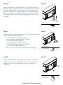
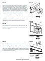
Step 13
Locate top (11). Turn top (11) upside down on a soft, clean surface.
Insert 4 cam lock dowels (d) into the holes on top (11). Make sure the
threaded side is down so you can insert and tighten each cam lock
dowel (d) into each hole in top (11).
Step 14
This top is heavy. Two people are needed to lift and position top (11)
into place.
Place the top (11) with finished side facing up on the right storage
side panel (6) and left storage side panel (7). Make sure the holes
line up with the wood dowels (a) in the right storage side panel (6),
left storage side panel (7) and the cam lock dowels (d) already in
the top (11). Press down on top (11) until flush with the right storage
side panel (6) and left storage side panel (7).
Once flush, tighten the 4 cam locks (e) on the top inside of the left
side storage panel (7) and the right side storage panel (6). Do not
strip the cam locks (e) by overtightening them. Place 1 plastic cam
cap (f) onto each of the 4 cam locks (e).
Step 15
Locate the 2 back panels (10) and the storage back panel (9).
Make sure the finished sides of the panels faces in toward the
mantel. Line up a back panel (10) so it is flush to the back of the
left side panel interior (5) and left side panel exterior (3). Secure
with 11 washer head wood screws (g) – 4 down each side and
3 across the bottom. Tighten until secure. Repeat for the other back
panel (10).
Line up the storage back panel (9) so it is flush to the back of the
left and right storage side panels (6 and 7) and the top (11). Secure
with 22 washer head wood screws (g) – 2 down each side and 10
across the top and 8 across the bottom. Tighten until secure.
Step 13
Step 14
Hardware Used
f Plastic Cam Cap x 4
Step 15
Hardware Used
g
W
asher Head
Wood Screw
x 44
Hardware Used
d Cam
Lock Dowels x 4
11
d
11
f
6
7
11
9
10
10
g
6

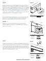
Step 16
Locate the right door (12) and left door (13). Open the hinges on
each of the right side panel exterior (2) and left side panel exterior
(3). Place the open side of each hinge into the recessed area on
each of the right door (12) and left door (13). Insert and tighten 2
hinge screws (k) into each of the 2 holes in each hinge. Make sure
the doors are level. You can adjust the doors at this point in your
assembly.
Step 17
Locate shelves (14) and mounting pegs (l). Press 8 mounting pegs (l)
into position on the following parts:
• 2 mounting pegs (l) into each of the
exterior left and right side panels (2 and 3)
for a total of 4 mounting pegs (l).
• 2 mounting pegs (l) into each of the
interior left and right side panels (4 and 5)
for a total of 4 mounting pegs (l).
Place 1 shelf (14) on each set of 4 level mounting pegs (l).
Step 18
Add 1 wood handle (h) to each door by inserting 1 small bolt (i)
from the inside of the door through the hole and into the wood
handle (h). Tighten with small bolt (i) until secure. Repeat for
other door.
Step 16
Hardware Used
k Hinge Screw x 8
Step 17
Hardware Used
l Mounting Pegs x 8
Step 18
Hardware Used
i Small Bolt x 2
h W
ood Handle x 2
13
12
k
13
12
14
l
7
13
12
h
h

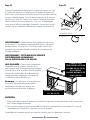
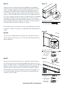
Step 19
Locate the fireplace insert. Install fireplace insert from the back of
the mantel. Once you have the fireplace insert into position and
square at the front, locate fireplace insert brace (15). Press fireplace
insert brace (15) up against the back of the fireplace insert making
sure that you DO NOT cover any air venting. Once the fireplace
insert brace (15) is snug, insert and tighten 2 medium flat head
wood screws (J) into the base (1) to attach it to the mantel securely.
Your fireplace insert is now sitting firmly in place.
You must attach the anti-tipping device to the mantel and the wall.
This device is a safety feature that will prevent the mantel from
tipping over. Applied weight may cause mantel imbalance.
Step 20
Attach one of the mounting brackets (n) securely to the back
underside edge of the mantel. Use 2 flathead small screws (o) to
make sure it is secure.
Step 21
Determine where mantel is to be placed and mark location on the
wall for the mounting bracket (n) screw holes. The mounting bracket
(n) on the wall should be positioned vertically. Insert a wall anchor
(q) into each screw hole in the wall. Place the mounting bracket (n)
over the marks on the wall and use the large screws (p) to securely
attach the mounting bracket (n) to wall.
Step 19
Hardware Used
J
F
lat Head
Medium Screw
x 2
Hardware Used
o
F
lat Head
Small Screw
x 2
n
Mounting
Bracket
x 1
Hardware Used
q W
all Anchor x 2
p
F
lat Head
Large Screw
x 2
n
Mounting
Bracket
x 1
FIREPLACE
INSERT
FIREPLACE
INSERT
15
J
Step 20
EDGE OF
MANTEL
BRACKET
SMALL
SCREWS
o
n
Step 21
q
n
p
WALL
8

9
Step 22
Place the mantel so the mounting bracket (n) on the back of the
mantel is in line with the mounting bracket (n) on the wall. Place an
end of the nylon strap (m) down through each bracket. Bring both
ends together and slide the end of the nylon strap (m) through the
slot in the other end until snug. Pull down on the end until it locks
into the slot. Check to make sure the nylon strap (m) is securely
laced and locked to the mounting brackets (n).
WARNING: Young children may be injured by tipping furniture.
The use of a tipping restraint is highly recommended. This
hardware, when properly installed, could provide protection
against the unexpected tipping of furniture due to improper use.
WARNING: THIS PRODUCT IS ONLY A DE
TERRENT. IT IS NOT
A SUBSTITUTE FOR PROPER ADULT SUPERVISION.
CAUTION:
This unit is intended for use only
with the products and maximum weights
indicated. Use with other products or products
heavier than the maximum weights indicated
may result in instability causing possible injury.
Note: Flat Panel TVs with base support should
be placed squarely in the center of the stand
with no overhang on any side.
Step 22
WALL
MANTEL
Hardware Used
m Nylon Strap x 1
CARE AND MAINTENANCE
1. Dust your fireplace mantel regularly with a soft non-lint producing cloth or household dusting
product.
2. You can clean your fireplace insert with a gentle non-abrasive household cleaner. Make sure to dry
your immediately with a soft cloth or towel.
This mantel comes with a touch up pen for any minor repairs.
n
m
n
FIT UP TO 60" PLASMA/
LCD TELEVISIONS
MAXIMUM LOAD
110 lb. (50 kg)
MAXIMUM LOAD
30 lb. (13.6kg)

WARRANTY
Greenway Home Products is pleased to offer in-home warranty repairs. Please refer to your Firebox Use and Care Guide for warranty
information on your Firebox.
DO NOT RETURN THIS PRODUCT TO THE STORE:
Please contact Customer Service at: 1-866-253-0447
Monday to Thursday from 8:30AM to 5:00PM (EST), Friday from 8:30AM to 4:00PM (EST)
Web: www.greenwayhp.com
Email: support@greenwayhp.com
Canada:
400 Southgate Dr., Guelph, Ontario, Canada, N1G 4P5
USA: 1270 Flagship Dr., Perrysburg, Ohio, USA, 43551
Limited Warranty Definitions:
Greenway Home Products:
(
Greenway) Manufacturer.
Mantel: Mantel manufactured by Greenway Home Products.
Purchaser: Purchaser of the Mantel
Distributor: Facility authorized to sell Greenway Home Products.
Warranty Card Greenway Home Products Limited Warranty Registration Card identifying the Purchaser and product model.
Greenway Limited Warranty:
Greenway warrants to the Purchaser that the Mantel is free from defects in material and workmanship, under normal use and service, for
1 year (1 year limited parts) from the date of purchase.
All warranty repairs must be preauthorized by Greenway Home Products. Greenway will, at its’ option, replace or repair free of charge
any defective part, which the Purchaser shall notify their Distributor or Greenway Home Products within the warranty period. The obligation
of Greenway Home Products under this warranty, is expressly limited to such replacement or repairs.
The provisions of this limited warranty shall not apply to the following:
1
. Accidents.
2. Unauthorized repairs or alterations.
3. Normal maintenance.
4
. Changes made to other units manufactured after this mantel was manufactured.
5. Incidental damages caused by failure of the mantel such as inconvenience or loss of use.
6.
Improper installation.
The provisions of this limited warranty shall not apply to deterioration due to wear and exposure beyond the following limitations:
1
. For 180 days from the date of purchase for exterior finished surfaces.
Due to the properties of natural wood, Greenway Home Products makes no warranty against mineraling of wood components.
Greenway Limited Warranty is void unless the following conditions are adhered to:
1
. Warranty registration must be completed and returned to a Greenway Home Products.
2. All warranty repairs must be preauthorized by a Greenway repair facility.
3. Greenway reserves the right to inspect defective parts that have been replaced under warranty. Dealer is expected to hold
defective parts for 60 days.
4. Only parts and accessories and other materials, available through Greenway Home Products are to be used in the performance
of warranty service.
5. Purchasers are responsible for presenting/notifying their Distributor as soon a problem exists. The warranty repairs should be
completed in a reasonable amount of time from the date of authorization. Not to exceed 30 days past notification.
This limited warranty is expressly in lieu of any other expressed or implied warranty, including any implied warranty or merchantability
or fitness for a particular purpose and of any obligations or liabilities on Greenway Home Products which neither assumes nor
authorizes any other person to assume for it any other liability in connection with the Mantel manufactured by it.
The warranty is null and void if used in commercial or industrial applications.
10

CONSEILS POUR L’ASSEMBLAGE DE VOTRE NOUVEAU MANTEAU
Avant d’entreprendre l’assemblage, trouvez les instructions et les articles de quincaillerie. Sortez les
composants et comparez-les par rapport aux schémas ci-dessous. Assurez-vous que vous avez toutes les
pièces et que vous pouvez les identifier.
L’aide d’une autre personne est toujours bienvenue. Assemblez votre manteau avec l’aide d’un autre
adulte si c’est possible. Certains composants sont lourds et l’autre personne pourra les tenir. Il vous faudra
environ 30-60 minutes pour faire l’assemblage.
1
DISPOSITIF ANTI-TIP
2 TROUSSES
MATÉRIEL TOUCHE DE
PEINTURE
BASE 1 PC
ZZ.2513SCN.01
DESS
US 1 PC
ZZ.2513SCN.11
É
TAGÈRE 2 PCS
ZZ.2513SCN.14
PANNEA
UX LATÉRAL
DROIT 1 PC
ZZ.2513SCN.06
PANNEA
UX LATÉRAL
GAUCHE 1 PC
ZZ.2513SCN.07
P
ANNEAU LATÉRAL DROIT
DE L’EXTÉRIEUR 1 PC
ZZ.2513SCN.02
P
ANNEAU LATÉRAL
GAUCHE DE
L’EXTÉRIEUR 1 PC
ZZ.2513SCN.03
PANNEAU ARRIÈRE 2 PCS
ZZ.2513SCN.10
P
ANNEAU LATÉRAL DROIT
DE L’INTÉRIEUR 1 PC
ZZ.2513SCN.04
P
ORTES DROITE 1 PC
ZZ.2513SCN.12
P
ANNEAU LATÉRAL
GAUCHE DE
L’INTÉRIEUR 1 PC
ZZ.2513SCN.05
P
ORTES GAUCHE 1 PC
ZZ.2513SCN.13
S
UPPORTS POUR
LE FOYER 1 PC
ZZ.2513SCN.15
PANNEAU
CENTRAL 1 PC
ZZ.2513SCN.08
PANNEA
U ARRIÈRE DE
RANGEMENT 1 PC
ZZ.2513SCN.09
1
11
8
9
15
10
7
6
14
2 3
4 5
12 13
a d e f
8 PCS
g
1 PC
b c
1 PCS 2 PCS 2 PCS 2 PCS2 PCS
8 PCS2 PCS2 PCS44 PCS8 PCS16 PCS16 PCS8 PCS8 PCS24 PCS
2 PCS
h i J k l m n o p q

2
PRÉPAREZ-VOUS À COMMENCER
Avant de commencer l’assemblage, utilisez des ciseaux pour
déballer les pièces de leur emballage. N’UTILISEZ PAS de couteau
à les boîtes ou un couteau x-acto pour ne pas couper le manteau
à l’intérieur de la boîte et pour ne pas endommager la finition.
Vérifiez le sac ROUGE contenant les articles de quincaillerie; ce
sac se trouve à l’intérieur de l’emballage; le sac est fixé à l’aide
de ruban adhésif sur la boîte supérieure. Assurez-vous que vous ne
jetez aucune pièce.
Étape 1
Placez la base (1) sur le sol. Ne la placez pas encore contre le
mur, car vous devrez accéder à l'arrière du manteau pendant
l'assemblage.
Étape 2
Insérez quatre vis Camloc (d) dans les trous de la base (1), tel qu'il
est illustré. Assurez-vous que le côté fileté pointe vers le bas afin que
vous puissiez insérer et serrer les vis Camloc (d) dans chacun des
trous de la base (1).
Étape 3
Repérez le panneau latéral intérieur droit (4) et le panneau latéral
intérieur gauche (5). Insérez deux goujons en bois (a) dans les deux
trous situés au bas du panneau latéral intérieur droit (4) et au bas
du panneau latéral intérieur gauche (5). Insérez les deux attaches
Camloc (e) dans les trous situés au bas du panneau latéral extérieur
droit (4) et du panneau latéral intérieur gauche (5). Veuillez vous
assurer que les flèches sur les quatre attaches Camloc (e) pointent
vers le bas en direction de la base (1).
Étape 1
1
Étape 2
Quincaillerie utilisée
d
Vis Camloc
x 4
1
d
Étape 3
Quincaillerie utilisée
a
Goujon en bois
x 4
e
Attache
Camloc
x 4
1
5
4
e
a
a

43
Étape 4
Alignez les trous de la base (1) avec les goujons en bois (a) et les
trous du panneau latéral intérieur droit (4) et du panneau latéral
intérieur gauche (5) avec les vis Camloc (d) insérées dans la
base (1). Appuyez sur les panneaux jusqu'à ce qu'ils s'insèrent
parfaitement. Serrez les attaches Camloc (e). Évitez de serrer
excessivement les attaches Camloc (d) afin de ne pas les abîmer.
Étape 5
Repérez le panneau latéral extérieur droit (2) et le panneau latéral
extérieur gauche (3). Insérez deux goujons en bois (a) dans les
deux trous situés au bas du panneau latéral extérieur droit (2) et au
bas du panneau latéral extérieur gauche (3). Alignez les goujons
(a) avec les trous de la base, puis appuyez sur les panneaux pour
les insérer parfaitement.
Étape 6
Lorsque les panneaux latéraux extérieurs droit (2) et gauche (3) ont
parfaitement été insérés dans la base (1), glissez quatre grands
boulons (b) dans des rondelles (c), puis vissez-les dans la base de
chaque panneau extérieur. Serrez-les fermement.
Étape 4
1
5
4
Étape 5
Quincaillerie utilisée
a
Goujon en bois
x 4
1
2
3
a
Étape 6
Quincaillerie utilisée
b
Grand boulon
x 4
c
Rondelle
x 4
b
c
1
2
3

43
Étape 7
Insérez huit goujons en bois (a) dans les trous situés sur le dessus des
panneaux latéraux extérieurs droit (2) et gauche (3) et des panneaux
latéraux intérieurs droit (4) et gauche (5). Insérez quatre attaches
Camloc (e) dans les trous situés sur le dessus des panneaux latéraux
intérieurs droit (5) et gauche (4). Veuillez vous assurer que les flèches
sur les quatre attaches Camloc (e) pointent vers le haut afin de
permettre l'assemblage de la tablette centrale (8).
Étape 8
Repérez la tablette centrale (8). Insérez quatre vis Camloc (d) dans
les trous situés sur le dessus de la tablette centrale (8). Insérez
quatre vis Camloc dans les trous situés sous la tablette centrale
(8). Assurez-vous que le côté fileté pointe vers le bas afin que vous
puissiez insérer et serrer les vis Camloc (d) dans chacun des trous
de la tablette centrale (8).
Étape 9
Alignez les vis Camloc (d) situées sous la tablette centrale (8) avec les
trous situés sur le dessus des panneaux latéraux intérieurs droit (4) et
gauche (5). Alignez les huit goujons en bois avec les trous situés sous
la tablette centrale (8). Appuyez sur la tablette centrale jusqu'à ce
qu'elle s'insère parfaitement dans la partie inférieure.
Après l'avoir parfaitement insérée, serrez les quatre attaches Camloc
(e) situées à l'intérieur des panneaux latéraux intérieurs droit (5) et
gauche (4). Évitez de serrer excessivement les attaches Camloc (e) afin
de ne pas les abîmer.
Insérez deux grands boulons (b) avec des rondelles (c) dans le
panneau latéral extérieur droit (2), puis vissez-les dans la tablette
centrale (8). Serrez-les fermement. Procédez de la même façon pour le
panneau latéral extérieur gauche (3).
Étape 7
Étape 8
Étape 9
Quincaillerie utilisée
a
Goujon en bois
x 8
e
Attache
Camloc
x 4
Quincaillerie utilisée
b
Grand boulon
x 4
c
Rondelle
x 4
1
2
3
5
4
a
a
e
8
Quincaillerie utilisée
d
Vis Camloc
x 8
d
d
8
1
2
3
5
4
b
c

Quincaillerie utilisée
a
Goujon en bois
x 4
e
Attache
Camloc
x 4
Étape 10
Insérez quatre goujons en bois (a) dans les trous situés sur le dessus
de la tablette centrale (8). Repérez le panneau latéral droit de
l'unité de rangement (6) et le panneau latéral gauche de l'unité de
rangement (7). Insérez une attache Camloc (e) dans chacun des
deux trous au bas des panneaux latéraux droit (6) et gauche (7) de
l'unité de rangement. Veuillez vous assurer que les flèches sur les
quatre attaches Camloc (e) pointent vers le bas afin de permettre
l'assemblage de la tablette centrale (8).
Étape 11
Alignez les trous situés sur les panneaux latéraux droit (6) et gauche (7)
de l'unité de rangement avec les goujons en bois (a) et les vis Camloc
(d) situés sur la tablette centrale (8). Appuyez sur les panneaux latéraux
de l'unité de rangement afin de les fixer sur la tablette centrale (8).
Après les avoir par
faitement insérés, serrez les quatre attaches Camloc
(e) situées à l'intérieur des panneaux latéraux droit (7) et gauche (6) de
l'unité de rangement. Évitez de serrer excessivement les attaches Camloc
(e) afin de ne pas les abîmer. Placez un capuchon en plastique (f) sur
chacune des quatre attaches Camloc (e).
Étape 12
Insérez les goujons de bois (a) dans les deux trous situés au centre des
panneaux latéraux droit (7) et gauche (6) de l'unité de rangement. Insérez
une attache Camloc (e) dans chacun des deux trous situés à l'intérieur de
la partie supérieure des panneaux latéraux gauche (7) et droit (6) de l'unité
de rangement. Veuillez vous assurer que les flèches sur les quatre attaches
Camloc (e) pointent vers le haut afin de permettre l'assemblage du dessus
(11).
Étape 10
Étape 11
Quincaillerie utilisée
f
Capuchon en
plastique
x 4
Quincaillerie utilisée
a
Goujon en bois
x 4
e
Attache
Camloc
x 4
e
a
a
7
6
8
Étape 12
e
a
a
7
6
8
f
7
6
8
65

Étape 13
Repérez le dessus (11). Placez le dessus (11) à l’envers sur une surface
douce et propre. Insérez quatre vis Camloc (d) dans les trous situés sur le
dessus (11). Assurez-vous que le côté fileté pointe vers le bas afin que vous
puissiez insérer et serrer les vis Camloc (d) dans chacun des trous du dessus
(11).
Étape 14
Le dessus (11) est lourd. Vous aurez besoin de l’aide d’une autre personne
pour le soulever et le mettre en place.
I
nstallez le dessus (11) sur les panneaux latéraux gauche (6) et droit (7) de
l'unité de rangement de manière à placer le côté fini vers le haut. Assurez-
vous d'aligner les trous avec les goujons en bois (a) qui se trouvent dans les
panneaux latéraux droit (6) et gauche (7) de l'unité de rangement et avec les
vis Camloc (d) déjà insérées dans le dessus (11). Appuyez sur le dessus (11)
pour l'insérer parfaitement dans les panneaux latéraux gauche (6) et droit (7)
de l'unité de rangement.
A
près l'avoir parfaitement inséré, serrez les quatre attaches Camloc (e) situées
à l'intérieur de la partie supérieure des panneaux latéraux gauche (7) et
droit (6) de l'unité de rangement. Évitez de serrer excessivement les attaches
Camloc (e) afin de ne pas les abîmer. Placez un capuchon en plastique (f) sur
chacune des quatre attaches Camloc (e).
Étape 15
Repérez les deux panneaux arrière (10) et le panneau arrière de l'unité de
rangement (9). Assurez-vous que les côtés finis des panneaux sont orientés
vers le manteau. Placez l'un des panneaux arrière (10) de façon à l'aligner
parfaitement avec l'arrière du panneau latéral intérieur gauche (5) et
l'arrière du panneau latéral extérieur gauche (3). Fixez-le à l'aide des onze
vis à bois avec tête à rondelle (g); quatre à la verticale de chaque côté et
trois à l'horizontale dans le bas. Serrez-les fermement. Procédez de la même
façon pour l’autre panneau arrière (10).
Placez le panneau arrière de l'unité de rangement (9) de façon à l'aligner
parfaitement avec l'arrière des panneaux latéraux gauche (6) et droit (7)
de l'unité de rangement et avec le dessus (11). Fixez-le à l'aide des 22
vis à bois avec tête à rondelle (g); deux à la verticale de chaque côté, dix
à l'horizontale dans le haut et huit à l'horizontale dans le bas. Serrez-les
fermement.
Étape 13
Étape 14
Quincaillerie utilisée
f
Capuchon en
plastique
x 4
Étape 15
Quincaillerie utilisée
g
Vis à bois avec
tête à rondelle
x 44
Quincaillerie utilisée
d
Vis Camloc
x 4
11
d
11
f
6
7
11
9
10
10
g
65

13
12
h
h
Étape 16
Repérez la porte droite (12) et la porte gauche (13). Ouvrez les
charnières des panneaux latéraux extérieurs droit (2) et gauche (3).
Placez le côté ouvert de chaque charnière dans l'encastrement de
la porte droite (12) et dans celui de la porte gauche (13). Insérez
et serrez deux vis à charnière (k) dans les deux trous de chaque
charnière. Assurez-vous que les portes sont de niveau. À cette étape
de l'assemblage, vous pouvez encore ajuster les portes.
Étape 17
Repérez les tablettes (14) et les taquets de fixation (l). Posez les huit
taquets de fixation (l) sur les pièces suivantes :
• deux taquets de fixation (l) dans les panneaux latéraux
extérieurs droit et gauche (2 et 3), pour un total de quatre
taquets (l);
• deux taquets de fixation (LL) dans les panneaux latéraux
intérieurs droit et gauche (D et E), pour un total de quatre
taquets (l).
Posez une tablette (14) sur chaque ensemble de quatre taquets de
fixation (l).
Étape 18
Ajoutez une poignée en bois (h) dans chaque porte en insérant
un petit boulon (i) dans le trou, puis dans la poignée en bois (h),
à partir de l'intérieur de la porte. Serrez le petit boulon (i) pour la
fixer. Faites de même pour l’autre porte.
Étape 16
Quincaillerie utilisée
k
Vis à charnière
x 8
Étape 17
Quincaillerie utilisée
l
Taquet de fixation
x 8
Étape 18
Quincaillerie utilisée
i
Petit boulon
x 2
h
Poignée
en bois
x 2
13
12
k
13
12
14
l
87

Étape 19
Repérez le foyer encastrable (emballé séparément). Installez-le à
partir de l'arrière du manteau. Lorsque le foyer encastrable est
en place et bien aligné à l'avant, repérez la traverse pour foyer
encastrable (15). Appuyez la traverse pour foyer encastrable (15)
contre l'arrière du foyer encastrable en veillant à NE PAS obstruer
la bouche d'aération. Lorsque la traverse pour foyer encastrable
(15) est bien en place, insérez et serrez deux vis à bois à tête plate
moyennes (J) dans la base (1) pour la fixer solidement au manteau.
Votre foyer encastrable est maintenant solidement fixé.
Vous devez fixer le dispositif antibasculement au manteau et au
mur. Ce dispositif de sécurité empêche le manteau de basculer.
L’application d’un poids pourrait déséquilibrer le manteau.
Étape 20
Fixez solidement un support de fixation (n) au rebord arrière du
manteau. Servez-vous de deux petites vis à tête plate (o) afin de
bien fixer ce support.
Étape 21
Déterminez l'emplacement voulu du manteau, puis faites une
marque sur le mur à l’endroit où entreront les petites vis du support
de fixation (n). Posez le support de fixation (n) verticalement au mur.
Insérez une cheville d'ancrage (q) dans chaque trou de vis percé
dans le mur. Placez le support de fixation (n) par-dessus les marques
sur le mur, puis servez-vous des grandes vis (p) pour fixer solidement
le support de fixation (n) au mur.
Étape 19
Quincaillerie utilisée
J
Vis moyenne
à tête plate
x 2
Quincaillerie utilisée
o
Petite vis
à tête plate
x 2
n
Traverse
x 1
Quincaillerie utilisée
q
Cheville d’ancrage
x 2
p
Grande vis
à tête plate
x 2
n
Traverse
x 1
15
J
Étape 20
o
n
Étape 21
q
n
p
FOYER
ENCASTRABLE
FOYER
ENCASTRABLE
PETITE
VIS
TRAVERSE
REBORD DU
MANTEAU
MUR
87

Étape 22
Disposez le manteau de façon que le support de fixation (n) situé
à l’arrière du manteau soit aligné avec le support de fixation (n)
fixé au mur. Faites passer une extrémité de la courroie de nylon (m)
à travers chaque support. Tirez les deux extrémités de la courroie
de nylon (m) l'une vers l'autre, puis insérez l'extrémité plate dans
l'autre extrémité en forme de boucle. Tirez sur l'extrémité plate
jusqu’à ce qu’elle se bloque dans la boucle. Assurez-vous que la
courroie (m) est solidement attachée aux supports de fixation (n).
AVERTISSEMENT : Le basculement d’un meuble peut blesser les
jeunes enfants. Il est fortement recommandé d’utiliser un dispositif
antibasculement. Un tel article, s'il est bien installé, fournit une
protection contre le basculement accidentel d’un meuble en cas
d’usage inadéquat.
AV
ERTISSEMENT : CETTE MESURE DE SÉCURITÉ
SUPPLÉMENTAIRE NE REMPLACE
PA
S LA SUPERVISION D’UN ADULTE.
MISE EN GARDE :
Cette unité est uniquement
compatible avec les produits spécifiés et ne
peut supporter que la charge maximale indiquée.
Le fait d’utiliser cette unité avec d’autres produits
ou avec des produits dont le poids excède la
charge maximale indiquée peut entraîner de
l’instabilité et causer des blessures.
Remarque : Les téléviseurs à écran plat munis
d'une base de soutien doivent être placés
complètement au centre du support sans
qu'aucune partie de la base ne dépasse.
Étape 22
Quincaillerie utilisée
m
Courroie
de nylon
x 1
ENTRETIEN
1. Époussetez régulièrement le manteau à l’aide d’un linge doux et non pelucheux ou d’un accessoire
pour l’époussetage domestique.
2. Vous pouvez nettoyer le foyer encastrable à l’aide d’un nettoyant doux et non abrasif. Essuyez-le
immédiatement à l’aide d’un linge doux ou d’une serviette.
L’emballage du manteau contient un crayon à retouche pour les réparations mineures.
n
m
n
MUR
MANTEAU
109
CONVIENT AUX
TÉLÉVISEURS À ÉCRAN
PLASMA OU ACL DE 60
PO
OU MOINS
CHARGE MAXIMALE DE
50 KG (110 LB)
CHARGE MAXIMALE DE
13,6 KG (30 LB)
La page charge ...
La page charge ...
La page charge ...
La page charge ...
La page charge ...
La page charge ...
La page charge ...
La page charge ...
La page charge ...
La page charge ...
La page charge ...
-
 1
1
-
 2
2
-
 3
3
-
 4
4
-
 5
5
-
 6
6
-
 7
7
-
 8
8
-
 9
9
-
 10
10
-
 11
11
-
 12
12
-
 13
13
-
 14
14
-
 15
15
-
 16
16
-
 17
17
-
 18
18
-
 19
19
-
 20
20
-
 21
21
-
 22
22
-
 23
23
-
 24
24
-
 25
25
-
 26
26
-
 27
27
-
 28
28
-
 29
29
-
 30
30
-
 31
31


Muskoka MTVSC2513SBP Assembly Instructions Manual
- Taper
- Assembly Instructions Manual
dans d''autres langues
- English: Muskoka MTVSC2513SBP
- español: Muskoka MTVSC2513SBP
Documents connexes
-
Muskoka MTVS2530SE Mode d'emploi
-
-
-
-
-
-
-
-
Autres documents
-
 Ornamental Mouldings CLASSIC5WHW Guide d'installation
-
 ESTATE by RSI CLDRK16SW Guide d'installation
-
 Blue Hawk BHBDD27GB Guide d'installation
-
Estate CLSHK16SW Assembly/Installation Instructions
-
Home Decorators Collection OME-66002 Guide d'installation
-
Ornamental RUSTIC3WM Mode d'emploi
-
FMI W26LTF Manuel utilisateur
-
General Tools 314038 Guide d'installation
-
 Pearl Mantels 418-60-90 Guide d'installation
-
 Pearl Mantels 412-72-10 Guide d'installation


