
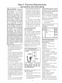
For Thermador ProfessionaP Cooktops
'l
Des tables de cuisson Thermador
Professional ®
IAnAmer_co,_Ico_°
ModeLs
P24GE
P24WK
PC30
PC36
PC48

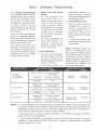
Contents
Warnings .................................................................................... Below
Introduction ........................................................................................ 1
Important Installation Information ........................................................ 2
Step 1: Ventilation Requirements ...................................................... 3
Step 2: Cabinet Preparation ......................................................... 4 - 7
Step 3: Unpacking, Moving, Placing and Anchoring the Cooktop ....... 8
Step 4: Gas Requirements and Hookup ..................................... 9- 10
Step 5: Electrical Requirements, Connection and Grounding .......... 11
Step 6: Backguard Installation .......................................................... 12
Step 7: Burner Test and Adjustment ........................................... 13 - 14
Installer Checklist ............................................................................. 15
To Clean and Protect Exterior Surfaces ............................................ 15
mMPORTANT mNSTALLATmON mNFORMATmON
WARNtNG:
If the information in this manual is not
followed exactly, a fire or explosion may
result causing property damage, personal
injury or death.
-- Do not store or use gasoline or other
flammable vapors and liquids in the vicinity
of this or any other appliance.
-- WHAT TO DO _F YOU SMELL GAS
• Do not try to fight any appliance.
• Do not touch any electrical switch.
• Do not use any phone in your building.
• Immediately call your gas supplier from a
neighbor's phone. Follow the gas supplier's
instructions.
• If you cannot reach your gas supplier, call
the fire department.
-- Installation and service must be performed
by a qualified installer, service agency or the
gas suppler.
Improper installation, adjustment, alteration,
service or maintenance can cause injury or
property damage. Refer to this manual. For
assistance or additional information consult
a qualified installer, service agency, manu-
facturer (dealer) or the gas supplier.
Note: This Cooktop is NOT designed for
installation in manufactured (mobile) homes or
for installation in Recreational Park Trailers.
DO NOT install this appliance outdoors.
DATA RATING PLATE
Cooktop Mode_s:
The data rating plate showing the model and serial
numbers of your Cooktop or Wok is located on the
underside of the Cooktop or Wok chassis near
the gas inlet connection and electdc power cord.
This information is required if customer service is
requested. Before installation the model and serial
numbers should be entered in the a_riate
spaces in the "BEFORE CALLING FOR SERVICE"
section near the back of the Care and Use Manual.
After installation accessing the information is
difficult.
For Massachusetts mnstaHations:
1. Installation must be performed by a qualified or licensed contractor, plumber or gas
fitter qualified or licensed by the state, province or region where this appliance is being
installed.
2. Shut-off valve must be a "T" handle gas cock.
3. Flexible gas connector must not be longer than 36 inches.

PLEASE READ ENTmRE mNSTRUCTmONS BEFORE PROCEEDmNG
mMPORTANT: LOCAL CODES VARY. INSTALLATION, ELECTRICAL CONNECTIONS,
GAS CONNECTIONS, AND GROUNDING MUST COMPLY WITH ALLAPPLICABLE CODES.
H'_PORTANT: Save these instructions for the Local Electrical Inspector's use.
_NSTALLER: Please leave these Installation instructions with this unit for the owner.
OWNER: Please retain these instructions for future reference.
ELECTRICAL POWER SUPPLY:
24" Models
with Wok - 120 VAC, 60 Hz., 1 Ph., 10Amp circuit
with Griddle - 240 VAC, 60 Hz., 1 Ph., 30 Amp circuit
30" Models:
4 Burners- 120 VAC, 60 Hz., Ph., 10Amp circuit
36" Models:
6 Burners - 120 VAC, 60 Hz., 1 Ph., 10 Amp circuit
with Grill - 120 VAC, 60 Hz., 1 Ph., 10 Amp circuit
with 12" Electric Griddle - 120 VAC, 60 Hz., 1 Ph., 15Amp circuit
48" Models:
6 Burners with Grill - 120 VAC, 60 Hz., 1 Ph., 10Amp circuit
6 Burners with 12" Electric Griddle - 120 VAC, 60 Hz., 1 Ph., 15Amp circuit
4 Burners with 12" Electric Griddle and Grill - 120 VAC, 60 Hz., 1 Ph., 15Amp circuit
4 Burners with Wok - 120 VAC, 60 Hz., 1 Ph., 10 Amp circuit
4 Burners with 24" Electric Griddle - 240 VAC, 60 Hz., 1 Ph., 30 Amp circuit
GAS SUPPLY:
Natural Gas -
Propane Gas -
6" min. to 14" max. water column.
(14.9 to 34.9 mb)
11"min. to 14"max. water column.
(27.4 mb to 34.9 mb)
WARNING
Disconnect power before installing.
Before turning power ON, be sure that
all controls are in the OFF position.
Introduction
All sealed burners are rated at 15,000 BTUiHR
('13,000 BTUiHR on LP), *All models, except 24"
Griddle, are convertible to LPiPropane gas using
an accessory conversion kit.
• Verify that the appliance is correct for the type
of gas being provided. Refer to Step 4 before
proceeding with the installation.
H'vlPORTANT
A backguard must be utilized when there is
less than a 12" horizontal clearance between
combustible materials and the back edge
of the cooktop. The Thermador Low Back
backguard must be ordered separately and
installed at the rear of the cooktop. For island
installations and other installations with more
than 12" clearance, an optional stainless steel
Island Trim is available to cover the backguard
mounting flanges.

Important Installation information
This appliance has been CSA
certified for safe operation up to
an elevation of 10,200 ft. without
any modifications. Exception: For
use with Propane, the appliance
must be converted per the LP
Conversion Instructions.
It is stron Ig_ recommended
that this appliance be installed
in conjunction with a suitable
overhead vent hood. (See Step
1 for Ventilation Requirements.)
Check local building codes for
the proper method of appliance
installation. Local codes vary.
Installation, electrical connections
and grounding must comply
with all applicable codes. In
the absence of local codes the
appliance should be installed
in accordance with the National
Electric Code ANSI Z223.1
current issue and National Gas
Code ANSI/NFPA 70 - current
issue. In Canada, installation
must be in accordance with
the CAN 1-B149.1 and .2-
Installation Codes for Gas
Burning Appliances and/or local
codes.
This appliance is equipped
with an intermittent/interrupted
ignition device that cycles the
two far left surface burners on
and off when in the ExtraLow _R*
setting.
CAUTION
(1) Whenconnectingtheunitto
propane gas, make certain
the propane gas tank is
equipped with its own
high-pressure regulator in
addition to the pressure
regulator su pplied with this
unit. The maximum gas
pressure to this appliance
is not to exceed 14.0
inches water column (34.9
mb) from the propane gas
tank regulator.
(2) This unit is designed as a
cooking appliance. Based
on safety considerations,
never use it for warming
or heating a room.
Due to the high heat of the
cooktop burners, installing a
microwave oven with a ventilation
system over the cooktop is not
recommended.
This appliance complies with
one or more of the following
standards:
UL 858, Standard for the
Safety of Household Electric
Ranges
• UL 923, Standard for the
Safety of Microwave Cooking
Appliances
UL 507, Standard for the
Safety of Electric Fans
• ANSI Z21.1 American National
Standard for Household Cooking
Gas Appliances
CANiCSA-C22.2 No. 113-
M1984 Fans and Ventilators
CANiCSA-C22.2 No. 61-M89
Household Cooking Ranges
It isthe responsibility of the owner
and the installer to determine if
additional requirements and/or
standards apply to specific
installations.
CAUTION
To eliminate risk of burns or
fire caused by reaching over
heated surface units, cabinet
storage located above the
surface units should be
avoided.
Remove all tape and packaging
before using the appliance.
Destroy the packaging after
unpacking the appliance. Never
allow children to play with
packaging material.

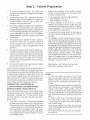
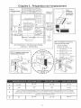
Step 1 Ventilation Requirements
It is strongL_L recommended
that a suitable exhaust hood be
installed above the appliance.
Downdraft ventilation should
not be used. The table below
indicates the Thermador hoods,
by model number, that are
recommended for use with the
24" wok, 24" griddle, 30", 36" and
48" cooktops.
Due to the high heat capability
of this unit, particular attention
should be paid to the hood and
duct work installation to assure it
meets local building codes.
Do not install a microwave oven/
ventilator combination above
the cooktop, as these types of
units do not provide the proper
ventilation and are not suitable
for use with the cooktop.
1. Semect Hood and B_ower
Models:
+ For wall installations the
hood width must, at a
minimum, equal the nominal
width of the appliance
cooking surface. Where
space permits, a hood larger
in width than the cooking
surface may be desirable
for improved ventilation
performance.
+ For island installations the
hood width should, at a
minimum, overhang the
appliance cooking surface
by 3" on each side.
2. Hood Placement:
+ For best smoke elimination,
the lower edge of the hood
should be installed 36"
above the appliance cooking
surface. (See Fig. 1).
+ If the hood contains any
combustible materials (i.e.,
a wood covering), it must be
36" or greater distance above
the cooking surface.
3. Consider Make-Up Air:
+ Due to the high volume of
ventilation air, a source of
outside replacement air
is recommended. This is
particularly important for
tightly sealed and insulated
homes.
+ A qualified heating and
ventilating contractor should
be consulted.
NOTE: Ventilation hoods and
blowers are designed for use
with single-wall ducting. Some
local building codes may require
double-wall ducting. Before
starting installation, consult local
building codes and agencies to
insure that the installation will
meet local requirements.
PH30CS, PHE30/36 VTR1030D, VTR1530D
24" WOK
24" GRIDDLE
30" COOKTOP
36" COOKTOP
48" COOKTOP
HNW36YS
PHH30DS***
PH36CS/42CS
PHE36/42
HNW36YS/42YS
PH36DS***
PH48CS/54CS
PHE48/60
HNW48YS
or VTN1030C
VTR 1030D, VTR1530D
N/A
VTR 1030D, VTR1530D
or VTN1030C
VTR 1030D, VTR1530D
N/A
VTR 1030D, VTR1530D
or VTN1030C
VTR 1030D, VTR1530D
HNI42YS VTR1030D or
HTNI42YS VTR1530D
HNI42YS VTR1030D or
HTNI42YS VTR1530D
HNI48YS/54YS, VTR1530D
HTNI48YS/54YS
NOTES: * For wall installations where adequate space is available, the installer or user may elect to use
a hood that is wider than the cooktop cooking surface. This may be particularly beneficial for
installations having a long duct run or when heavy usage of the grill or wok is anticipated, in
which improved capturing of the cooking exhaust is desired.
•* Thermador offers a choice of remote (VTRI030D or VTR1530D) or internal (VTN 1030C)
blowers for use in wail installations.
•** Hood models PHH30DS and PHH36DS include a 600-CFM built-in blower. For optimal
ventilation, a hood model with 1000-CFM blower or greater is recommended for cooktops
having a griddle, grill, or wok.

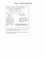
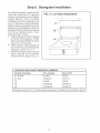
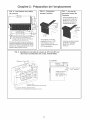
Step 2: Cabinet Preparation
I. To ensure professional results, the cabinet and
countertop openings should be prepared bya qualified
cabinet worker.
2. The clearances shown in Fig. I are required. The same
clearances apply to island installations, except for the
overhead cabinets, which must have a space wide
enough to accept the island hood.
3. The cooktop isdesigned to hang from the countertop by
its sideflanges. Thecountertop however, must bestrong
enoughtosupportthis heavycooktop. Itmaybe necessaq/
to add a supporting cleat along each side (see Fig. 2) or
a 2 x 4 corner brace (see Figs. 3 and 4 and Detail A).
Another alternative would be to construct a deck to set
the cooktop on.
4. The cooktop can be installed in various positions
with the front either flush or projecting, depending
on the countertop's depth. (See Fig. 5, side view of
cooktop; see Figs. 3,4, 6 and 7for alternate mounting
positions.)
5. The gas and electrical supply must be located in an
area that isaccessible without requiring removal ofthe
cooktop. The appliance electrical power cord and gas
pipe connection are located on the left rear underside
of the cooktop (except on models with a 24" griddle
where power cord is located in the center), as shown
in Figs. 5 and 9.
6. The maximum depth of over head cabinets installed
on either side of the hood is 13".
A 364nch minimum clearance is required between the top
of the cooktop and the bottom of an unprotected cabinet. A
364nch distance can be used when the bottom d thewood
or metal cabinet is protected by not less than I/4 inch d a
flame retardant material covered with not less than No. 28
MSG sheet steel, 0.015 inch (0A mm) thick stainless steel,
0.024 inch (0.6 ram)aluminum, or 0.020 inch (0.5 mm)thick
copper. Flame retardant materials bear the mark:
UNDERWRITERS LABORATORIES INC.
CLASSIFIED MINERAL AND FIBER BOARDS
SURFACE BURNING CHARACTERISTICS
followed by the flame spread and smoke ratings. These
designations are shown as "FHC (Flame Spread/Smoke
Developed)." Materials with "O" flame spread ratings
are flame retardant. Local codes may allow other flame
spread ratings.
7. When there is less than a 12" horizontal clearance
between combustible material A and the back edge
ofthe cooktop above thecooking sudace, a Thermador
Low Back backguard must be installed. (See Step 6).
When clearance to combustible material A isover
12", a Thermador Island Trim may be used. Attach
the backguard before sliding the appliance into the
final installed position.
8. Establish the centerline of the cooktop's desired
location. It should be the same as the center of the
overhead ventilation hood.
9. Cut the openings for the following installations:
• Wail installation, see Fig. 3.
• Island installation, see Fig. 4.
I0. For flush installations as shown in Fig. 7, provide
clearance for the three screws located along the
underside of the cooktop leading edge by increasing
the cutout height by 1/16" or by notching the cabinet
at the location of the three screws.
11. For models with a griddle, attach the foam strip to
countertop centered along the rear about 1/16" from
the edge.
12. For installation of a 48" cooktop above two side-by-
side Thermador Warming Drawers, Model No. WD24,
refer to Fig. 8. Completing the installation as per Fig.
8 will result in the left and right edges of the cooktop
being aligned with the left edge ofthe ieftosidewarming
drawer and rightedge tithe right-side warming drawer.
If different alignment is desired, the IW/8" horizontal
distance between warming drawer cutouts may be
varied. However, maintain at least a 1-I/8" distance
to avoid interference between the warming drawers.
Attach a 90-degree elbow to the gas cooktop inlet
pipe. All above4he-countertop clearances must be
maintained, as shown in Fig. I.
AAs defined in the "National Fuel Gas Code"
(ANSI Z223.1/NFPA54-current issue).
NOTES:
• If a solid side cabinet wall exists on one or both
sides, you will need to notch the front corner of the
cabinet to match the countertop notch and to allow
clearance for the cooktop front (see Detail A, Figs.
3 and 4).
• Ifa supporting deck isused, the sides or bottom ofthe
cutout may be solid combustible or noncombustible
material. If the bottom is solid, provide a 8" by 8"
cutout in the left rear corner of the supporting deck.
This will provide clearance for the gas inlet and power
cord, while also allowing viewing of the product rating
label.
• On models which have a 24" griddle with power
cord in the center, provide 2 (two) separate pieces
of supporting deck to allow clearance in center for
cord to pass through.
. Always keep appliance area clean and free from
combustible materials, gasoline and other flammable
vapors and liquids.
• Donotobstructthe flowofcombustion and ventilation
air to the unit.

Step 2: Cabinet Preparation
FIG. 1
Clearance
Requirements
i
I
30"to38"WideHoodfor24"Wokor 24"Griddle
30"to38"WideHoodfor30"Cooktop
_' to42"WideHoodfo_ Combustible
48"to80"WideHoodfor48"Cooktopt Material A
VENT HOOD _ _ --
M
t
36" from bottom of Over-
head Hood to Cooking @
@ Surface (36" or greater if
,, hood contains combus° 36" Min. to
13 Max. tible materials A ). Horizontal [:ii_!:l Combustible
| depth of Min. Clearance [!ii_i] MaterialZ_,from
overhead to,Rear Wa [-_:!] Cooking
cabinets [ /0 withBackguard I_i_i:1 Surface.!
18" Min,,bothside _- .4L_ --[ / 12" W/OBackguard __ 0" Bottom
AAs defined in the "National Fue! Gas Code"
(ANSI Z223.1, Latest Edition).
FIG. 3 War[ Installation with
Countertop Backsp[ash
_ DetailA _
(Front face of cabinet) _ %
%
/
I
_ 7o13/16"
\
CORNER NOTCH
_%_ DETAIL _
FIG. 2
Installing
Side Supports
(both sides)
Counter
'_ Sunk
Screws
FBG. 4 Island Installation
No Countertop Backsp[ash)
Vent Hood
Width Requirements
Island- 42"or48"WideHoodfor24"WokorGriddle
Island- 42"or48"WideHoodfor36"Cooktop
Island- 48"54"or60"WideHoodfor48"C00kt0p
A 24-3/4" 29-7/8" 35-7/8" 47-7/8"
B 3/8" 3/8" 3/8" 13/1 6"
0" (Control Panel Projecting 2" from BaseCabinet Face)
C 5/8" (Notch Recuired for Standard 24"-Deep BaseCabinet, Control Panel Projecting 1-3/8" from Base
Cabinet Face) 2" (Control Panel Flush to Cabinet Face - Min. 25-3/8"-Deep Base Cabinet Required)
D 24" 29-1/8" 35-1/8" 46-1/4"

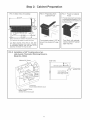
Step 2: Cabinet Preparation
FIG. 5 Side View of Cooktop
Low Back required when there is tess than
12" horizontal clearance from back of cooktop
to combustible matedat. With more than 12" of
clearance, the Island Trim may be used.
FIG. 6 Projecting from
Cabinet Front
1=3/8"
Front projects outward 1o3/8" as
shown from standard 24"-deep
base,
FIG. 7 Flush to Cabinet
Front
* Provide clearance for screws by
increasing cutout height by 1/16"
or by notching in the location of
the three screws,
_>"Notch
Depth
Front flush with cabinets;
minimu mof25=3/8"cabinet
depth required.
HG. 8 mnstaLlation of 48" Cooktop above two
side=by=side Thermador Warming Drawers,
Model No. WD24
Minimum3/4"
Side View
t 7-W16"
Plywood support "_(19,8 cm)
[
Install additional `2#
wood support along
front edge of cutout
P
3/4" (70 ram) minin
between cutot
1-7/8"(4,8cm)
H0riz0ntdDistanceBetweenCutouts
2-3/4"(7 cm)VerticalDistance
BetweenCutouts
(SeeSideViewfor WoodSupport)

Step 2: Cabinet Preparation
F_G, 9 Front = Bottom of Unit, See Detail B, Below
3-Prong grounding type
receptacleconnected to
a properly grounded and
polarized electrical supply
ratedat 120VAC, I0 Amps,
( or 15A*) Single Phase,
60 HZ. NOTE: This is not
applicable to 240 VAC
models with 24" electric
griddle. **
9
A manual valve must be
installed external to the
appliance, in an accessible
location from the front, for
the purpose of shutting off
the gas supply.
AH _nstaHer supplied parts
must conform to Loca_ Codes.
"15 Amp 120 VAC electrical supply is required for 36" and
48" models with a 24" electric griddle.
**30 Amp 240 VAC electrical supply is required for models
with a 24" electric griddle.

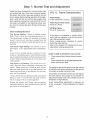
Step 3: Unpacking, Moving, Placing
and Anchoring the Cooktop
,
.
.
CAUTION
Proper equipment and adequate manpower
must be used in moving the appliance to avoid
damage and/or personal injury. The unit is
heavy and should be handled accordingly.
Remove the outer carton and packing material
from the shipping base. Ensure that you have
all cooktop components before proceeding.
Remove the top grate castings, burner caps
and grill grate (if so equipped) to reduce unit
weight.
NOTE: Leave adhesive-backed foam layer
over brushed-metal surfaces, to protect finish
from scratches, until the cooktop is installed
in its final position.
Lift and place the cooktop in the opening. Be
careful not to pinch the power cord or gas inlet.
Care should be taken not to scratch the griddle
or the griddle frame.
.
IMPORTANT
• Verify that the appliance is correct for
the type of gas being provided. Refer
to Step 4 before proceeding with the
installation.
• Attach the backguard before sliding the
appliance into the final installed position.
See Step 6.
Ensure that the power line cord is free and
hanging loose.
5. Level the appliance. For proper performance,
the appliance must be level.
6. The grill frame (if so equipped) has been leveled
during assembly so do not attempt to level the
grill.
.
Replace the top grate castings, burner caps
and grill grate (if so equipped). Ensure that the
burner caps are correctly seated on the burner
bases.
Griddle Ti t Adjustment
Check the griddle adjustment by pouring two tablespoons of water on the back of the griddle
plate. The water should slowly roll into the grease tray. If not, adjust the two screws under the
back of the griddle. Start with one half turn counter-clockwise (CCW) of the screws. Further
adjustment should be made by one-quarter turn until water slowly flows into the grease tray.

Step 4: Gas Requirements and Hookup
Cooktops are shipped by the factory to operate
on natura_ gas. They must be converted for use
with propane. Verify the type of gas being used
at the installation site matches the type of gas
used by the appliance, If the Eocat{onijob site re-
quires conversion from natural gas to propane (LP),
contact the dealer where the unit was purchased
or contact Thermador. The field conversion kit for
all Professional cooktops (PC series) is Thermador
Model PLPKIT. Obey all instructions in PLPKIT for
correct conversion of the gas regulator and settings
for the gas valves. Field conversion must be done
by qualified service personnel only.
This appliance has been CSA certified for safe op-
eration up to an elevation of 10,200 ft. without any
modifications. Exception: For usewith propane, the
appliance must be converted per the LP conversion
instructions.
Please refer to your LP Conversion Instructions for
further information.
Natural Gas Requirements:
Inlet Connection: 1/2" NPT (min. 3/4" dia. flex line)
Supply Pressure: 6" min. to 14" max. water
column (14.9 to 34.9 mb)
Manifold Pressure: 5" water column (12.5 mb)
Propane Gas Requirements:
Inlet Connection: I/2" NPT (min. 3/4" dia. flex line)
Supply Pressure: 11" min. to 14" max. water
column (27.4 mb to 34.9 mb)
Manifold Pressure: 10" water column (24.9 mb)
WARNING"
This conversion kit shall be installed by
a qualified service agency in accordance
with the manufacturer's instructions and
all applicable codes and requirements
of the authority having jurisdiction. If the
information in these instructions is not
followed exactly, a fire, explosion or pro-
duction of carbon monoxide may result
causing property damage, personal in-
jury or loss of life. The qualified service
agency is responsible for the proper in-
stallation of this kit. The installation is not
proper and complete until the operation
of the converted appliance is checked as
specified in the manufacturer's instruc-
tions supplied with the kit.
HOOK UP
A manual gas shut-off valve must be installed
external to the appliance, in a location acces-
sible from the front, for the purpose of shutting
off the gas supply. The supply line must not
interfere with the back of the unit. Make sure the
gas supply is turned off at the manual shut-off
valve before connecting the appliance.
The installer should inform the consumer of the
location of the gas shut-off valve. Make sure all
users know where and how to shut off the gas
supply to the cooktop.
The gas supply connections shall be made by
a competent technician and in accordance with
local codes or ordinances. In the absence of a
local code, the installation must conform to the
National Fuel Gas CodeANSI Z223.1iNFPA54=
current issue.
Always use pipe-sealing compound or Teflon _
tape on the pipe threads, and be careful not to
apply excessive pressure when tightening the
fittings.
Leak testing of the appliance shall be in
accordance with the following instructions.
Turn on gas and check supply line connections
for leaks using a soap and water solution.
Bubbles forming indicate a gas leak. Repair
all leaks immediately after finding them.
Do not use a flame of any kind to check
for gas _eaks.
• All installer-supplied parts must conform to
applicable codes.

Step 4: Gas Requirements and Hookup
CAUTION:
When connecting unit to propane gas, make
certain the propane gas tank is equipped with
its own high pressure regulator in addition
to the pressure regulator supplied with the
appliance. The pressure of the gas supplied
to the appliance regulator must not exceed
14" water column (34.9 mb).
CAUTION
The appliance must be isolated from the gas
supply piping system by closing its individual
manual shut-off valve during any pressure
testing of the gas supply piping system at
test pressures equal to or less than 1/2 psig
(3.5kPa.).
"The appliance and its individual shut off valve
must be disconnected from the gas supply
piping system during any pressure testing of
the system at test pressures in excess of 1/2
psig (3.5kPa.)."
When checking the manifold gas pressure,
the inlet pressure to the regulator should be
at least 6.0" W.C. for natural gas or 11.0" for
propane.
Do not attempt any adjustment of the pressure
regulator.
10

Step S: Electrical Requirements,
Connection and Grounding
CAUTnON: mmproper
grounding or reverse
_o_arization will cause
malfunction (such as
continuous sparking of the
burner igniters). This can
damage the appliance and
can create a condition of
shock hazard. If the circuit
is not correctly grounded
and polarized, it is the
responsibility and obligation
of the installer and user to
have the existing receptacle
changed to a properly
grounded and polarized
receptacle. This must be
accomplished in accordance
with aHapplicable _ocal codes
and ordinances bya qualified
e_ectrician, mnthe absence of
_oca_ codes and ordinances,
the receptacle repRacement
shah be in accordance with
the Nationa_ Electric Code.
(See Fig.10.)
Before installing, turn power
OFF at the service panel. Lock
service panel to prevent power
from being turned ON acci-
dentally.
Always disconnect appliance
from the electric supply either
by disconnecting power cord or
shutting off the breaker before
servicing the appliance.
Before you plug in an electri-
cal cord, be sure all controls
are in the OFF position.
All 120 Volt cooktop models
must be plugged into a mating
3-Prong, Grounding-Type
Receptacle. The receptacle
must be connected to a properly
grounded and polarized electrical
power supply rated at 120VAC,
Single Phase, 60HZ. See list on
this page for proper over-current
protection requirements for each
model.
All 240 Volt cooktop models
require hard wire connections.
, Observe allgoverningcodes and
ordinances when grounding. In
the absence of these codes or
ordinances observe National
Electrical Code AN SI/N FPA No.
70 current issue. See Fig. 10
for recommended grounding
method.
o An electrical wiring diagram
and schematic have been
attached to the bottom of the
cooktop chassis for access by
a qualified service technician.
Do not remove or discard this
important information.
Grounding Method for
120 VAC Models
The cooktop is factory equipped
with a power supply cord with a
three-prong grounding plug (with
polarized parallel blades).
IT MUST BE PLUGGED INTO
A MATING, GROUNDING
TYPE RECEPTACLE THAT IS
CON NECTEDTOACORRECTLY
POLARIZED 120 VOLT CIRCUIT
(240 VOLT CIRCUIT FOR
MODELS WITH 24" ELECTRIC
GRIDDLE. (See Fig. 10).
FiG. 10 Recommended
Grounding Method for 120V
models
THE THIRD, GROUND
PRONG MUST NOT BE CUT
OR REMOVED UNDER ANY
C_RCUMSTANCES.
ElectricaJ Connection
240 VAC Models
I.
.
for
Attach flexible conduit to the
junction box.
Connect the cooktop lead wires
to the junction box supply wires
in proper phase:
11
For aii 240 VAC models, connect
Mack (L!) to black, red (L2) to
red, white wire to neutral and
green wire to ground.
Note: Ifthe 120V cooktop is install-
ed and connected as specified
above, it will be completely
grounded in compliance with the
National Electric Code.
3. Turn on power supply.
4. Test operation.
FIG. 11 Junction Box
Location
Conduit
L 12" APPROXIMATE _
1 j
"J" Box
Electrical Power Supply
Over-current Protection
Requirements:
4 Burners - 10 Amp circuit
protection
6 Burners - 10 Amp circuit
protection
4 Burners with a grill- 10Amp
circuit protection
4 Burners with a 12" electric
griddle - 15 Amp circuit protection
6 Burners with a grill- 10Amp
circuit protection
6 Burners with a 12" electric
griddle - 15 Amp circuit protection
4 Burners with a grill and a 12"
electric griddle - 15 Amp circuit
protection
4 Burners with a wok- 10Amp
circuit protection
4 Burners with a 24" electric
griddle -30 Amp circuit protection,
240VAC
Cooktop with a wok - 10 Amp
circuit protection
Cooktop with a 24" electdc
griddle - 30 Amp circuit
protection 240 VAC.
Installer - show the owner the
location of the circuit breaker or
fuse. Mark it for easy reference.

Step 6: Backguard Installation
ALow Back backguard must be installed
when there is less than a 12" clearance
between combustibles and back edge of
cooktop. (See Fig. 1 and 5.) For island
installations and other installations with
over 12" clearance, an optional stainless
steel trim channel isavailable to cover the
backguard mounting flanges. Attach the
backguard before sliding the appliance
into the final installed position. Follow
Steps A through C below:
A. Slide backguard over the two flanges
on the rear of the appliance. Fasten
the front and back with the two screws
(see A, Fig. 12)provided.
B. Fasten the top of the backguard to
the wall with two screws through the
backguard. (See B, Fig. 12.)
C. Place the backguard cap on top and
fasten using the two counter-sink
screws provided. (See C, Fig. 12.)
FIG. 12 Low Back Attachment
C _/
A
®
LOW BACK AND ISLAND TRIM MODEL NUMBERS
Cooktop Size/Type 12" Low Back
24" Griddle PC24LB
24" Wok GP24LBS
30" PC3OLB
36" GPS36LBS
48" GPS48LBS
Island Trim*
PC241T
GP241TS
PC301T
GPS361TS
GPS481TS
*Requires a minimum of 12" horizontal clearance between back of appliance and combustible materials.
12

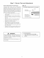
Step 7: Burner Test and Adjustment
Install any loose components, such as burner caps
and grates that may have been removed earlier.
Be certain that burner caps seat properly into the
burner bases. Before testing operation of the appli-
ance, verify that the unit and the gas supply have
been carefully checked for leaks and that the unit
has been connected to the electrical power sup-
ply. Turn the manual gas shut-off valve to the open
position.
Test Cooktop Burners
Test Burner Ignition. Select a cooktop burner
knob. Push in and turn counterclockwise to HI.
The ignitor/spark module will produce a clicking
sound. Once the air has been purged from the
supply lines, the burner should light within four (4)
seconds.
Test Flame: High Setting. Turn burner on to HI.
See Figure 13 for appropriate flame characteris-
tics.
If any of the cooktop burners continue to burn
mostly or completely yellow, verify that the burner
cap is positioned properly on the burner base, then
re-test. If flame characteristics do not improve, call
Thermador@.
Test Flame: Low Setting. Turn burner on to LO.
Verify that the flame completely surrounds the
burner. There should be a flame at each burner
port and there should be no air gap between the
flame and the burner. If any burners do not carry
over, call Thermador®.
The two far left burners feature XLO®, causing the
flame to cycle on and off when the knob is set to
the XLO range. This is normal operation.
Repeat the Ignition and Flame Test procedures
described above for each cooktop burner and the
grill burner (if so equipped).
FiG. 13 Flame Characteristics
Yellow Flames:
Further adjustment is required.
Yellow Tips on Outer Cones:
Normal for LP Gas.
Soft Blue Flames:
Normal for Natural Gas.
If the flame is completely or mostly yellow,
verify that the regulator is set for the correct
fuel. After adjustment, retest.
Some orange-colored streaking is normal
during the initial start-up.
Allow unit to operate 4-5 minutes and re-eval-
uate before making adjustments.
WHEN FLAME IS PROPERLY ADJUSTED:
. There should be a flame at each burner
port.
. There should be no air gap between the
flame and burner port.
The gas grill uses a tube-style burner that has an
air shutter which allows adjustment to the amount
of primary air inside the burner tube.
Air shutters of tube-style burners are pre-adjust-
ed at the factory, and usually do not require re-
adjustment except under rare conditions such as
installation at high altitude.
If grill burnedftame adjustment is required, go
to the procedure: "Flame Adjustment (if neces-
sary)".
13

Step 7: Burner Test and Adjustment
Flame Adjustment (if necessary):
Tube=style gas burners used in Thermador©
appliances have air shutter systems which are
similar to the illustration in Figure 14, and can be
adjusted using the following method (unless ad-
justment is not recommended). It is necessary to
remove the burner from the appliance in order to
perform air-shutter adjustments.
• Loosen shutter screw(s) and turn shutter to
new position.
Adjust the shutter to more-closed position if
the flame is lifting or blowing, or is not carry-
ing over.
Adjust the shutter to more-open position if
the flame is too yellow. (See Figure 14.)
• Retighten the shutter screw(s).
After adjustment, reinstall the burner and
perform flame evaluation. The air shutter
must fit over the orifice hood for proper opera-
tion of the burner.
• Repeat procedure as needed until flame char-
acteristics are acceptable. (See Figure 13.)
FiG. 14
Air Shutter Adjustment (if necessary)
More Open:
Less Yellow Ffame/_
Nore CJosed: \
Less Blue Flame
More Carryover
Less Lifting or Blowing
Screw
Air
Shutter
WARNING
Burner adjustments must be performed by a
qualified technician. Improper adjustments
may cause harmful by=products or void the
appliance's warranty.
Allow burners to cool before attempting to re=
move them!
Ca[[ Thermador@ if:
1. Any of the burners do not light.
2. Any of the burners continue to burn
yellow.
14

FmNAL CHECK UST
Cooktop correctly positioned
in countertop recess.
Specified clearances
maintained to cabinet
surfaces.
Burner caps positioned
propedy on burner bases.
All packaging material
removed. Note: Wok models
have tie-down straps around
the burner, which must be
removed before using the
appliance.
Island Trim or Backguard
attached according to
instructions.
The griddle/grill plate tilted
slightly forward. (See page 8
for adjustment procedure.)
GAS SUPPLY
Connection: 1/2" NPTwith a
minimum 3/4" diameter flex
line.
If converting from natural to
LP gas, refer to LP Conver-
sion Instructions for details.
OPERATION
Manual gas shut off valve
installed in an accessible
location (without requiring
removal of appliance).
Unit tested and free of gas
_eaks.
ELECTRICAL
For models with the 12" electric
griddle, a polarized and
grounded 120VAC receptacle
with 15 AMP overcurrent
protection is provided for
service cord connection.
For models with the 24" electric
griddle, a propedy grounded,
240 VAC service connection
with 30 AMP overcurrent
protection is provided.
All internal packing materials
removed. (Check below
grates and grill pans.)
Bezels centered on burner
knobs, and knobs turn
freely.
Purge unit with first burner.
Each burner lights
satisfactorily, both individually
and with other burners
operating.
Burner grates correctly
positioned.
mNSTALLER: Give CARE
and USE MANUAL
and INSTALLATION
INSTRUCTIONS to your
customer.
To C ean And Protect Exterior Surfaces
The stainless steel surfaces may be cleaned by
wiping with a damp soapy cloth. Any mild glass
cleaner will remove fingerprints and smears.
Follow all cleaning by rinsing with clearwater. Wipe
dry with a clean soft cloth to avoid water marks.
For discolorations or deposits that persist, use a
non-scratching household cleanser or stainless
steel polishing powder with a little water and a soft
cloth. For stubborn cases, use a plastic scouring
pad or soft bristle brush together with cleanser and
water. Rub lightly in direction of polishing lines or
"grain" of the stainless finish. Avoid using too much
pressure which may mar the surface.
Use a stainless steel cleaner/polish to protect the
finish and maintain appearance.
DO NOT allow deposits to remain for long periods
of time.
DO NOT use ordinary steel wool or steel brushes.
Small bits of steel may adhere to the surface
causing rust.
DO NOT allow salt solutions, disinfectants, bleaches
or cleaning compounds to remain in contact with
stainless steel for extended periods. Many of these
compounds contain chemicals which could prove
harmful. Rinse with water after exposure and wipe
dry with a clean cloth.
15

Table des mati res
Avertissements ..................................................................... 16 (ci-dessous)
Introduction ................................................................................................ 17
Information importante & propos de I'installation ........................................ 18
Chapitre 1 : Exigences de ventilation ......................................................... 19
Chapitre 2 : Pr6paration de Femplacement ........................................ 20 - 23
Chapitre 3 : D6ballage, manutention, mise en place et fixation
de la table de cuisson ................................................................................ 24
Chapitre 4 : Exigences pour I'alimentation du gaz et raccordement .... 25°26
Chapitre 5 : Exigences pour Falimentation 61ectrique, Je
branchement et la mise & la terre .............................................................. 27
Chapitre 6 : Installation de la plaque de protection .................................... 28
Chapitre 7 : Test et r6glage de brOleur ................................................. 29°30
Liste de v6rification de I'installateur ........................................................... 31
Nettoyage et protection des surfaces ext6rieures ...................................... 31
INFORMATIONS IMPORTANTES RELATIVES ,A,L'INSTALLATION
AVERTtSSEMENT ,"
L'information fournie darts le present
manuel dolt 6tre tres rigoureusement
respectee, sous peine d'incendie ou
d'explosion entra'_'nant des dommages,
des biessures ou la mort.
-- Ne stockez paset n'utilisez pas d'essence ou autres
produits inflammables a proximite des appareils.
--81VOUS SENTEZUNEODEURDE GAZ
• N'allumezaucun appareil.
• Ne touchez pas aux interrupteurs electriques.
• N'utilisez pas les tel6phones du b&timent.
• Appelez immediatement votre compagnie de gaz
de chez un voisin. Suivez les instructions de la
compagnie.
• Sivous n'arrivez pas & contacter la compagnie de
gaz, appelez les pompiers.
-- L'installation et les reparations doivent 6tre realisces
par un installateur qualifie, un centre de reparation
agr6e ou la compagnie de gaz.
,_ AVERTtSSEMENT
Une installation, un reglage, une modification,
une reparation ou un entretien adequat
peuvent entra'fner des bJessures ou des
d6g&ts materiels. Consultez le present manuel.
Pour de I'information supplementaire ou de
I'assistance, consultez un installateur qualifie,
un centre de reparation, le fabricant (revendeur)
ou la compagnie distributdce de gaz.
Remarque : Cette table de cuisson N'EST PAS
con_;ue pour les maisons mobiles ni pour les
vehicules recr6atifs.
NE PAS installer ce table de cuisson dehors.
FICHE SIGNALETJQUE
Modeles de tables de cuisson :
La plaque de caracteristiques indique le modele et
le numero de serie de votre table de cuisson ou de
votre wok. Erie est placee sur le dessous du chassis
de la table de cuisson ou du wok, prCs du raccord
d'arrivCe de gaz et du cordon d'alimentation elec-
trique. Cette information est requise par le Service
la clientele. Avant
les numeros de serie devrait 8tre entre darts les
esApaces a la rubricLue AVANT D'EFFECTUER UN
APPEL DE SERVICE a la fin du guide d'utilisation
et d'entretien. Lorsque I'appareil est installe, il est
difficile d'acceder a I'information.
Pour _es installations au Massachusetts :
1. L'installation doit 6tre realisee par un entrepreneur qualifie ou agree, un plombier ou
un installateur de gaz qualifie ou autorise par I'€:tat ou la region oQ cet appareil est
pose.
2. Le robinet d'arr6t de gaz doit _tre pourvu d'une poignee en <<T >>.
3. La Iongueur maximum autorisee du tuyau de gaz est de 91,4 cm (36").
16

VEUILLEZ LIRE TOUTES LES INSTRUCTIONS AVANT DE POURSUiVRE
IMPORTANT: LES R¢:GLEMENTATIONS LOCALES VARIENT. L'INSTALLATION, LES
BRANCHEMENTS €:LECTRIQUES, LES RACCORDEMENTS AU GAZ ET LA MISE A LA TERRE
DOWENT SATISFAIRE A TOUTES LES RE_GLEMENTATIONS APPLICABLES.
IMPORTANT : Conservez ces instructions pour Hnspecteur local de la compagnie d'electdcit&
iNSTALLATEUR : Veuillez laisser ces instructions d'installation avec I'appareil pour le propfietaire.
PROPRIETAJRE : Veuillez conserver ces instructions pour consultation ulterieure.
]
ALIMENTATJON _:LECTRJQUE :
Modeles 60 9 c_24_
avec wok- 120 VAC, 60 Hz., 1 Ph. circuit de 10A
avec grille - 240 VAC, 60 Hz. 1 Ph. circuit de 30 A
BrQleurs 4- 120 VCA, 60 Hz, monophas& circuit de 10 A
Modeles de
BrQleurs 6 : 120 VCA, 60 Hz, monophas& circuit de 10A
avec griJ: 120 VCA, 60 Hz, monophas& circuit de 10A
avec grille electrique 12 po :120 VAC, 60 Hz, monophas& cuicuit de 15 A
BrQleurs 6 avec gril : 120 VCA, 60 Hz, monophase, circuit de 10A
BrQleurs 6 avec grille electrique 12 po : 120 VCA, 60 Hz, monophase, circuit de 15 A
BrQleurs 4 avec grille electrique 12 po et gril : 120 VAC, 60 Hz, monophas& circuit de 15 A
BrQleurs 4 avec wok - 120 VCA, 60 Hz, monophas& circuit de 10 A
BrQieurs 4 avec grille electrique 24 po ((avec grille electrique 24 po) - 240 VAC, 60 Hz. 1 Ph. circuit de 30 A
ALIMENTATION EN GAZ :
Gaz naturei : 14,9 mb (6 po) min. a 34,9 mb (14 po) max.
& la colonne d'eau.
Gaz propane :27,4 mb (11 po) min. a 34,9 (14 po) max.
la colonne d'eau).
AVERTISSEMENT
Coupez 1'61ectdcite avant d'installer I'appareil.
Avant de remettre I'electdcit6, assurez-vous
que toutes les commandes sont a la position
OFF.
Introduction
Tousles brQleurs scelles sont cotes a 15 000 Btu/h ('13
000 BTu/h pour LP). *Tous les modeles, sauf celui avec
la grille 24 po, sont convertibles au gaz propane/LP
l'aide du necessaire de conversion.
IMPORTANT
° Une plaque de protection doit @tremise en place
lorsque ledegagement horizontal entre les matedaux
combustibles et le bord arriere de la table de
cuisson est de moins de 30,5 cm (12"). La plaque
de protection basse Thermador est a commander
separ6ment et doit @tre installee a I'arriere de
la table de cuisson. Pour les installations en riot
avec un degagement de plus de 30,5 cm (12"), un
enjoliveur en acier inoxydable est vendu en option
afin de recouvrir les brides de montage de laplaque
de protection.
Assurez-vous que I'appareil convient au type de gaz
fourni. Consultez le chapitre 4 avant de proceder
l'instalJation.
17

Information importante a propos de l'installation
Cet appareil est certifie ACNOR
& des fins de fonctionnement
secudtaire jusqu'& une el6va-
tion de 10 200 pi sans modifica-
tion. Exception :pour I'utilisation
avec le gaz propane, I'appareil
dolt 6tre converti selon les in-
structions de conversion au LP.
II est fortement recommande
d'installer une hotte de
ventilation adaptee au-dessus
de cet appareil (voir chapitre
1, Conditions de ventilation). A
cause de la chaleur intense que
peut degager cet appareiJ, on doit
porter une attention particuliere &
I'installation des conduits et de la
hotte afin quqls soient conformes
aux reglementations locales de
construction.
Vedfiez la reglementation locale
applicable & la construction pour
connaftre la methode appro-
priee d'installation de I'appareil.
,_ defaut de reglementation,
I'appareil doit etre installe
conformement aux versions
actuelles du Code national du
gaz combustible no Z223.1 et
du Code national de I'electricite
ANSIiNFPA70 ou aux Codes
d'installation pour les appareils
& gaz CAN 1-B149.1 et .2 et au
Code electrique canadien C22.1,
premiere pattie.
Assurez-vous que I'appareil
installer correspond au type de
gaz utilise sur le site.
Cet appareil est equipe d'un
systeme d'allumage intermittent
qui allume et eteint les deux
br01eurs de gauche Iorsqu'ils sont
r6gles sur ExtraLovT'RL
MtSE EN GARDE
(1) Si I'appareil est alimente
au gaz propane, assurez-
vous que le reservoir de
propane est equip6 de son
propre detendeur en plus
du detendeur foumi avec
I'appareil. La pression
maximum d'arrivee du
gaz dans cet appareil ne
doit pas depasser les 34,9
millibars (14 pouces & la
colonne d'eau) a partir du
detendeur du reservoir de
propane.
(2) Cet appareil est congu pour
un usage culinaire. Pour
des raisons de securite,
ne I'utilisez jamais pour
chauffer une piece.
A cause de la chaleur intense
produite par cet appareil, il faut
porter une attention particuliere
I'installation de la hotte et des
conduits afin de s'assurer qu'ils
repondent aux codes de con-
struction Iocaux.
Cet appareil est conforme avec
une ou plusieurs des normes
suivantes •
UL 858, norme pour la secu-
rite des cuisinieres electriques
domestiques
• UL 923, norme pour la secu-
rite des appareils de cuisson &
micro-ondes
• UL 507, norme pour les venti-
lateurs electriques
• ANSI Z21.1, norme nationale
americaine pour les appareils
de cuisson & gaz domestiques
•CAN/CSA-C22.2 n°113-M1984
ventilateurs et hottes
• CANiCSA-C22.2 n° 61-M89
cuisinieres domestiques
M!SE EN GARDE
Afin d'_[iminer [es
risques de br_lures
ou d'incendie pro-
voqu_s par la chal-
eur, il est conseiH_
d'_viter d'installer
des armoires au-des-
sus des appareils.
II incombe au proprietaire et &
I'installateur de determiner si
des exigences et/ou normes
additionnelles s'appliquent pour
une installation specifique.
Enlever tout le materiel
d'emballage et le ruban adhesif
avant d'utiliser I'appareil. Detru-
ire le materiel d'emballage une
fois I'appareil deball& Nejamais
laisser les enfants jouer avec ce
materiel d'emballage.
18
La page est en cours de chargement...
La page est en cours de chargement...
La page est en cours de chargement...
La page est en cours de chargement...
La page est en cours de chargement...
La page est en cours de chargement...
La page est en cours de chargement...
La page est en cours de chargement...
La page est en cours de chargement...
La page est en cours de chargement...
La page est en cours de chargement...
La page est en cours de chargement...
La page est en cours de chargement...
La page est en cours de chargement...
-
 1
1
-
 2
2
-
 3
3
-
 4
4
-
 5
5
-
 6
6
-
 7
7
-
 8
8
-
 9
9
-
 10
10
-
 11
11
-
 12
12
-
 13
13
-
 14
14
-
 15
15
-
 16
16
-
 17
17
-
 18
18
-
 19
19
-
 20
20
-
 21
21
-
 22
22
-
 23
23
-
 24
24
-
 25
25
-
 26
26
-
 27
27
-
 28
28
-
 29
29
-
 30
30
-
 31
31
-
 32
32
-
 33
33
-
 34
34


Thermador PCG304E01 Guide d'installation
- Catégorie
- Plaques électriques
- Taper
- Guide d'installation
dans d''autres langues
Documents connexes
-
Thermador PCG364NL Manuel utilisateur
-
Thermador PCG486GD Guide d'installation
-
-
-
-
-
-
-
-
Autres documents
-
Bosch NGM5664UC/01 Guide d'installation
-
Bosch NGM5054UC/03 Guide d'installation
-
Amana AKGD3050 Manuel utilisateur
-
 GE Monogram ZGU384N Manuel utilisateur
-
GE ZGU385L Manuel utilisateur
-
 GE Monogram Cooktop ZGU385L Manuel utilisateur
-
-

