Ideal Test-Pro Digital Multimeter Mode d'emploi
- Catégorie
- Multimètres
- Taper
- Mode d'emploi
Ce manuel convient également à

#61-340
#61-342
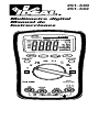
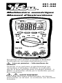
Digital Multimeter
Instruction Manual

Register your product and access more information at
www.idealindustries.com
Read First: Safety Information
Understand and follow operating instructions carefully.
Use the meter, test leads and all accessories only as
specified in this manual; otherwise, the protection
provided by the meter can be impaired.
WARNING
To avoid possible electric shock, personal injury or
death, follow these guidelines:
• Do not use if meter appears damaged. Visually inspect
the meter to ensure case and jaws are not cracked.
• Inspect and replace test leads if insulation is damaged,
metal is exposed, or probes are cracked. Pay particular
attention to the insulation surrounding the connectors.
• Always ensure the meter, test leads and all accessories
meet or exceed the measurement category required
in the working environment. (i.e. CAT rating)
• Note that the measurement category and voltage
rating of combinations of the meter, the test leads,
and the accessories is the lowest of the individual
components.
• Do not use meter if it operates abnormally as
protection maybe impaired.
• Do not use during electrical storms or in wet weather.
• Do not use around explosive gas, dust, vapor,
amperage or in damp or wet environments.
• Do not apply more than the rated voltage to the meter.
• Remove the test leads from the input jacks before
measuring current.
• Replace battery as soon as battery indicator
appears to avoid false readings.
• Remove the test leads from the meter prior to
removing battery cover.
• Do not use without the battery and battery cover
properly installed.
• Do not attempt to repair this unit as it has no user-
serviceable parts.
• Use the proper terminals, functions and range for
your measurements.
• Never ground yourself when taking electrical
measurements.
• Connect the black common lead to ground or neutral
before applying the red test lead to potential voltage.
Disconnect the red test lead from the voltage first.
• Keep fingers behind the guard rings of the probe tips.
• Voltages exceeding 30VAC or 60VDC pose a shock
hazard so use caution.

CAUTION
To protect yourself, think “Safety First”:
• Comply with local and national safety codes.
• Use appropriate personal protective equipment such
as face shields, insulating gloves, insulating boots,
and/or insulating mats.
• Before each use:
- Perform a continuity test by touching the test leads
together to verify the functionality of the battery
and test leads.
- Use the 3 Point Safety Method. (1) Verify meter
operation by measuring a known voltage.
(2) Apply
meter to circuit under test. (3) Return to
the known
live voltage again to ensure proper operation.
• Always work with a partner.
Test Leads
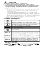
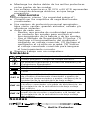
Symbols on the Unit
Risk of Danger. Important Information. See
Manual.
Hazardous voltage. Risk of electrical shock.
Application around and removal from Hazard-
ous Live conductors is permitted.
AC (Alternating Current)
DC (Direct Current)
Earth Ground
CAT II
Measurement Category II applies to test and
measuring circuits connected directly to utiliza-
tion points (socket outlets and similar points)
of the low-voltage MAINS installation
CAT III
Measurement Category III applies to measuring
circuits connected to the distribution part of the
building’s low-voltage MAINS installation
CAT IV
Measurement Category IV applies to test and
measuring circuits connected at the source of
the building’s low-voltage MAINS installation
~
...
Guard ring
CAT IV 600V
CAT III 1000V
CAT II 1000V

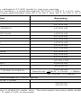
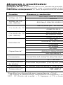
AC Converter: 61-340 model is averaging sensing, rms calibrated; 61-342 model is true rms sensing.
Accuracy: Accuracy is specified as +/-(a percentage of the reading + a fixed amount) at 23°C±5°C (73.4°F ± 9°F), less than 75% relative humidity.
Temperature Coefficient: 0.1 times the applicable accuracy specification from 32°F to 64°F and 82°F to 122°F (0°C to 18°C ; 28°C to 50°C).
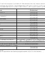
Ranges & Accuracies
Function Range & Resolution Accuracy Overload Protection
DC Voltage
400.0m/4.000/40.00/400.0 V ±(0.5%+5)
600.0V ±(1.0%+3)
AC Voltage
400.0m/4.000/40.00/400.0/600 V
±(1.5%+5)
(40~400Hz)
DC Current
400.0/4000 µA ; 40.00/400.0 mA ±(0.5%+5) 500mA/600V Fast Fuse
4.000/10.00 A ±(1.5%+5) 10A/1000V Fast Fuse
AC Current
400.0/4000 µA ±(1.5%+5)
500mA/600V Fast Fuse
(40~400Hz)
40.00/400.0 mA ±(2.0%+5)
4.000/10.00 A ±(2.5%+5) 10A/1000V Fast Fuse
400.0Ω ±(1.2%+5)
Resistance
4.000k/40.00k/400.0k Ω ±(1.0%+2)
600V DC/AC rms
4.000MΩ ±(1.2%+2)
40.00MΩ ±(2.0%+5)
40.00nF ±(3.0%+10)
Capacitance* 400.0n/4.000µ/40.00µ F ±(3.0%+5) 600V DC/AC rms
400.0µ/4000µ F ±(20%+5)
Frequency 10.00/100.0/1.000k/10.00k/100.0k/1.000M/10.00M Hz
±(0.1%+3)
600V DC/AC rms
Sensitivity: <1MHz: 0.7Vrms ; >1MHz: 5Vrms
Duty Cycle 0.1 - 99.9% ±(2.5%+5) (<10kHz)
Diode Check Test current : (1±0.6) mA and then open circuit voltage is 2.5VDC typical. 600V DC/AC rms
Continuity The beeper turns on <25Ω and turns off at >120Ω. 600V DC/AC rms
Temperature**
-58~1500°F ±(3.0%+5)
—
-50~800°C ±(3.0%+3)
*Accuracy not available for <10nF capacitance. **Accuracy is stated for meter only. Thermocouple accuracy adds another ±2.5% to reading.
Input Impedance : 10MΩ for VAC & VDC. CF > 2, add ±1.0% to accuracy.
Symbols on the Unit

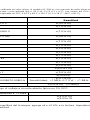
AC Converter: 61-340 model is averaging sensing, rms calibrated; 61-342 model is true rms sensing.
Accuracy: Accuracy is specified as +/-(a percentage of the reading + a fixed amount) at 23°C±5°C (73.4°F ± 9°F), less than 75% relative humidity.
Temperature Coefficient: 0.1 times the applicable accuracy specification from 32°F to 64°F and 82°F to 122°F (0°C to 18°C ; 28°C to 50°C).
Function Range & Resolution Accuracy Overload Protection
DC Voltage
400.0m/4.000/40.00/400.0 V ±(0.5%+5)
600.0V ±(1.0%+3)
AC Voltage
400.0m/4.000/40.00/400.0/600 V
±(1.5%+5)
(40~400Hz)
DC Current
400.0/4000 µA ; 40.00/400.0 mA ±(0.5%+5) 500mA/600V Fast Fuse
4.000/10.00 A ±(1.5%+5) 10A/1000V Fast Fuse
AC Current
400.0/4000 µA ±(1.5%+5)
500mA/600V Fast Fuse
(40~400Hz)
40.00/400.0 mA ±(2.0%+5)
4.000/10.00 A ±(2.5%+5) 10A/1000V Fast Fuse
400.0Ω ±(1.2%+5)
Resistance
4.000k/40.00k/400.0k Ω ±(1.0%+2)
600V DC/AC rms
4.000MΩ ±(1.2%+2)
40.00MΩ ±(2.0%+5)
40.00nF ±(3.0%+10)
Capacitance* 400.0n/4.000µ/40.00µ F ±(3.0%+5) 600V DC/AC rms
400.0µ/4000µ F ±(20%+5)
Frequency 10.00/100.0/1.000k/10.00k/100.0k/1.000M/10.00M Hz
±(0.1%+3)
600V DC/AC rms
Sensitivity: <1MHz: 0.7Vrms ; >1MHz: 5Vrms
Duty Cycle 0.1 - 99.9% ±(2.5%+5) (<10kHz)
Diode Check Test current : (1±0.6) mA and then open circuit voltage is 2.5VDC typical. 600V DC/AC rms
Continuity The beeper turns on <25Ω and turns off at >120Ω. 600V DC/AC rms
Temperature**
-58~1500°F ±(3.0%+5)
—
-50~800°C ±(3.0%+3)
*Accuracy not available for <10nF capacitance. **Accuracy is stated for meter only. Thermocouple accuracy adds another ±2.5% to reading.
Input Impedance : 10MΩ for VAC & VDC. CF > 2, add ±1.0% to accuracy.
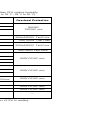
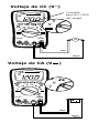
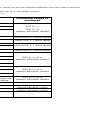
900VDC
750VAC rms

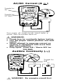
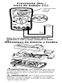
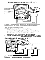
AC Voltage (V~)
DC
DC
DC Voltage (V
)
Toggle for
Frequency
(>20% of
range)

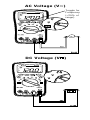
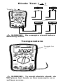
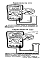
Capacitance ( )
nF
nF
WARNING: De-energize circuit before
taking resistance measurement.
WARNING: De-energize circuit and
discharge capacitor before taking capaci-
tance measurement.
Measuring time: < 15sec for <400µF
< 1min for <4000µF
MΩ
MΩ
Resistance (Ω)
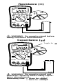
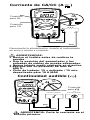
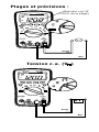
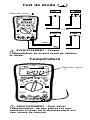
Toggle for

AC/DC Current (A
)
DC
A
Closed
Circuit
Open
Circuit
Ω
WARNING: De-energize circuit first.
~
Toggle for
AC
Toggle for
Hz
Toggle for
•
)
)
)
Closed
Circuit
Open
Circuit
Ω
Audible Continuity (
•
)
)
)
)
DC
A
Turn power off, break circuit, insert meter in
series, then turn power back on.
WARNINGS:
• Check fuse for continuity before testing.
• Use the proper switch position and lead
inputs.
• Never attempt to measure current on
circuits or equipment with more than
600 volts potential.
• Duty cycle: 15sec ON / 15min OFF for
10A MAX

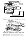
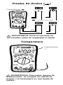
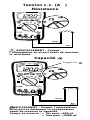
Bad Diode
Good Diode
Ope
nS
horted
Foward Reverse
Diode Test ( )
WARNING: De-energize circuit before
checking diode.
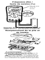
WARNING: To avoid electric shock, do
not place test leads or thermocouple on a
voltage source.
Toggle for
Bad Diode
Good Diode
Open Shorted
Foward Reverse
CAT II
MAX
300V
+
–
Temperature
Toggle for
°C
Bad Diode
Good Diode
Open Shorted
Foward Reverse
CAT II
MAX
300V

Hz
WARNING: To avoid electric shock, dis-
connect test leads before removing battery cover.
WARNING: For continued protec-
tion against fire, replace only with fuses of the
specified voltage, current and rupture speed rat-
ings.
Frequency (Hz) /
Duty Cycle(%)
Bad Diode
Good Diode
Open Shorted
Foward Reverse
CAT II
MAX
300V
(Remove tilt stand)
Toggle for
Duty Cycle
Battery & Fuse Replacement
Note: On noisy circuits, turn dial to V, then
toggle Hz button.
~

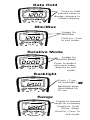
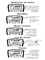
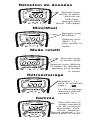
Data Hold
Hold
Press to hold
present value in
display; depress to
release display.
Min/Max
Relative Mode
Toggle for
Relative Mode
Press to deduct
reference value;
depress to exit
mode.
Backlight
Press >1 sec.
for backlight ( )
Backlight stays
illuminated for
10 sec.
Range
Toggle to manual
range on following
functions: Volts,
Ohms, Amps.
Hold for >1sec. to
exit mode.
Toggle for
Min/Max
Hold for >1sec.
to exit mode.
MAX MIN

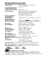
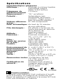
Specifications
General Features
Display: 3999 Count LCD / 3-3/4 Digit
Refresh Rate: 2.5x/sec.
Over range: “OL” is displayed
Polarity: Automatic (no indication for
positive polarity); Minus(-) sign
for negative polarity
True-RMS: 61-342 only.
Auto Power Off: After 10 minutes of non-use
Low Battery: is displayed if battery voltage
drops below operating voltage
Altitude: 6561.7 ft. (2000m)
Accuracy: Stated accuracy at 73° ±41°F
(23° ±5°C), < 75% R.H.
Batteries: 9VDC NEDA 1604
Battery Life: 200 hrs. (61-340)
150 hrs. (61-342)
Fuse: 0.5A/500V (#F-340)
10A/1000V (#F-341)
Operating 32° to 104°F (0° to 40°C)
environment: at < 75% R.H.
Storage -4° to 140°F (-20° to 60°C)
environment: at < 80% R.H.
Weight: 13.6 oz (386g)
Size: 7.0”H x 3.5”W x 1.9”D
(177mmHx89mmWx48mmD)
Accessories Test leads (TL-770), 9V battery,
Included: Operating Instructions
Safety Complies with UL/IEC/EN 61010-1,
Certification: 61010-031, Cat III-600V
Equipment protected by double
insulation.
Instrument has been evaluated and complies with
insulation category III (overvoltage category III) for
measurements performed in the building installa-
tion. Pollution degree 2 in accordance with IEC-644.
Indoor use.
N12966
+

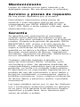
Maintenance
Clean the case with a damp cloth and mild deter-
gent. Do not use abrasives or solvents.
Service and Replacement
Parts
No user-serviceable parts.
For replacement parts or to inquire about service
information contact IDEAL INDUSTRIES, INC. at
1-877-201-9005 or visit our website @ www.
idealindustries.com.
Warranty Statement
This tester is warranted to the original purchaser
against defects in material and workmanship for
two years from the date of purchase. During this
warranty period, IDEAL INDUSTRIES, INC. will, at
its option, replace or repair the defective unit, sub-
ject to verification of the defect or malfunction.
This warranty does not cover fuses, batteries or
damage from abuse, neglect, accident, unauthor-
ized repair, alteration, or unreasonable use of the
instrument.
Any implied warranties arising out of the sale of
an IDEAL product, including but not limited to
implied warranties of merchantability and fitness for
a particular purpose, are limited to the above. The
manufacturer shall not be liable for loss of use of
the instrument or other incidental or consequential
damages, expenses, or economic loss, or for any
claim or claims for such damage, expenses or
economic loss.
State laws vary, so the above limitations or exclu-
sions may not apply to you. This warranty gives
you specific legal rights, and you may also have
other rights which vary from state to state.

#61-340
#61-342
Multímetro digital
Manual de
Instrucciones

Registre su producto y acceda a más información en
www.idealindustries.com
Lea Primero: Información de Seguridad
Entienda y siga las instrucciones de operación
cuidadosamente. Use el multímetro, las sondas y todos
los accesorios únicamente como se especifica en este
manual; de lo contrario, la protección que proporciona
el multímetro puede verse perjudicada.
ADVERTENCIA
Para evitar posibles riesgos de descarga eléctrica,
lesiones o la muerte, siga estas directrices:
• No use el multímetro si el mismo parece estar
dañado. Inspecciónelo visualmente para asegurarse
de que la cubierta y la pinza no estén quebradas.
• Inspeccione y reemplace los cables si el aislamiento
está dañado, hay metal expuesto o las sondas están
quebradas. Preste atención especial al aislante
alrededor de los conectores.
• Siempre asegúrese de que el multímetro, las sondas
y todos los accesorios cumplan o excedan la
categoría de medición necesaria en el ambiente de
trabajo. (Por ejemplo, clasificación CAT)
• Tome nota de que la categoría de medición y la
clasificación de voltaj e de combinaciones del
multímetro, la sondas y los accesorios es la más
baja de los componentes individuales.
• No use el multímetro si funciona en forma anormal,
porque la protección puede estar perjudicada.
• No use el multímetro durante tormentas eléctricas o
en clima húmedo.
• No use el multímetro cerca de gas, polvo, vapor,
amperaje explosivo o en ambientes húmedos o
mojados.
• No aplique voltajes superiores a las
nominales al multímetro.
• Quite las sondas de los puertos de entrada antes de
medir corriente.
•
Reemplace la batería tan pronto aparezca el indicador
de carga de batería baja, para evitar las lecturas falsas.
• Retire las sondas del multímetro antes de quitar la
tapa de la batería.
• No use el multímetro sin la batería, ni sin la tapa de
la batería correctamente instalada.
• No intente reparar esta unidad ya que no tiene piezas
reparables por el usuario.
• Use las terminales, funciones y rangos apropiados
para sus medidas.
•
No se conecte a tierra cuando tome medidase eléctricas.
• Conecte la sonda negra común a tierra o a neutro
antes de tocar la sonda roja a voltaje potencial.
Desconecte la sonda roja del voltaje primero.

• Mantenga los dedos detrás de los anillos protectores
en las puntas de las sondas.
•
Los voltajes superiores a 30 VCA o 60 VCD representan
un riesgo de descarga eléctrica, así que tenga
precaución.
PRECAUCIÓN
Para protegerse, piense “¡La seguridad primero!”:
• Cumpla con los requisitos de seguridad locales
y nacionales.
• Use equipos de protección personal apropiados,
tales como, caretas, guantes aislantes, calzado y/o
alfombras aislantes.
• Antes de cada uso:
- Realice una prueba de continuidad poniendo
en contacto las sondas para verificar el
funcionamiento de la batería y de las sondas.
- Use el Método de Seguridad de 3 Puntos. (1)
Verifique el funcionamiento del multímetro
midiendo un voltaje conocido. (2) Aplique el
multímetro al circuito en prueba. (3) Vuelva
al voltaje conectado conocido para asegurar
el funcionamiento correcto.
• Siempre trabaje con un compañero.
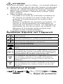
Símbolos
Riesgo. Información Importante. Vea el Manual.
Voltaje peligroso. Peligro de choque eléctrico.
Se permite la aplicación y el retiro de alrededor y de
Conductores Energizados.
CA (Corriente Alterna)
CD (Corriente Directa)
Tierra
CAT II
Categoría de Medición II aplica a la prueba y medición
de circuitos directamente conectados a puntos de
utilización (tomacorrientes y puntos similares) de la
instalación de la red eléctrica de bajo voltaje
CAT III
Categoría de Medición III aplica a la medición de
circuitos conectados a la parte de distribución de
la instalación de la red eléctrica de bajo voltaje
del edificio
CAT IV
Categoría de Medición IV aplica a la prueba y
medición de circuitos conectados a la fuente de
la instalación de la red eléctrica de bajo voltaje
del edificio
~
...
Sondas
Anillo Protector
CAT IV 600V
CAT III 1000V
CAT II 1000V

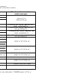
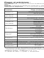
Alcances y exactitudes:
Alcances y exactitudes:
Conversor de CA:
El modelo 61-340 es con sensado de promedio, calibrado en valor eficaz; el modelo 61-342 es con sensado de valor eficaz verdadero.
Exactitud: La exactitud se especifica como +/-(un porcentaje de la lectura + una cantidad fija) a 23°C±5°C (73.4°F ± 9°F), con menos del 75% de humedad relativa.
Coeficiente de temperatura: 0.1 veces la especificación de exactitud aplicable de 32°F a 64°F y 82°F a 122°F (0°C a 18°C ; 28°C a 50°C).
Protección contra
Función Alcance y resolución Exactitud sobrecarga
Voltaje de CC
400.0m/4.000/40.00/400.0 V ±(0.5%+5)
600.0V ±(1.0%+3)
Voltaje de CA
400.0m/4.000/40.00/400.0/600 V ±(1.5%+5)
(40~400Hz)
Corriente de CC
400.0/4000 µA ; 40.00/400.0 mA ±(0.8%+3)
4.000/10.00 A ±(1.5%+5)
Corriente de CA
400.0/4000 µA ±(1.5%+5)
(40~400Hz)
40.00/400.0 mA ±(2.0%+5)
4.000/10.00 A ±(2.5%+5)
400.0Ω ±(1.2%+5)
Resistencia
4.000k/40.00k/400.0k Ω ±(1.0%+2)
600 V XC/CA ef.
4.000MΩ ±(1.2%+2)
40.00MΩ ±(2.0%+5)
40.00nF ±(3.0%+10)
Capacitancia* 400.0n/4.000µ/40.00µ F ±(3.0%+5) 600 V CC/CA ef.
400.0µ/4000µ F ±(20%+5)
Frecuencia 10.00/100.0/1.000k/10.00k/100.0k/1.000M/10.00M Hz
±(0.1%+3)
600 V CC/CA ef.
Sensibilidad: <1 MHz: 0.7 V ef. ; >1 MHz: 5V ef
0.1 - 99.9% ±(2.5%+5) (<10kHz)
Comprobación
de diodos
Corriente de prueba: (1±0.6) mA y luego el voltaje a circuito abierto típico es 2.5 VCC.
600 V CC/CA ef.
Continuidad El sonido (bip) se activa a <25Ω y se desactiva a >120Ω. 600V DC/AC rms
Temperatura**
-58~1500°F ±(3.0%+5)
—
-50~800°C ±(3.0%+3)
*Exactitud no disponible para capacitancia <10 nF.
**Se indica la exactitud del instrumento únicamente. La exactitud del termopar agrega otro ±2.5% a la lectura. Impedancia de entrada: 10MΩ para VCA y
VCC. CF (Factor de cresta) > 2, Agregue +/-1% a la exactitud.
Riesgo. Información Importante. Vea el Manual.
Voltaje peligroso. Peligro de choque eléctrico.
Se permite la aplicación y el retiro de alrededor y de
Conductores Energizados.
CA (Corriente Alterna)
CD (Corriente Directa)
Tierra
CAT II
Categoría de Medición II aplica a la prueba y medición
de circuitos directamente conectados a puntos de
utilización (tomacorrientes y puntos similares) de la
instalación de la red eléctrica de bajo voltaje
CAT III
Categoría de Medición III aplica a la medición de
circuitos conectados a la parte de distribución de
la instalación de la red eléctrica de bajo voltaje
del edificio
CAT IV
Categoría de Medición IV aplica a la prueba y
medición de circuitos conectados a la fuente de
la instalación de la red eléctrica de bajo voltaje
del edificio

Alcances y exactitudes:
Alcances y exactitudes:
Conversor de CA: El modelo 61-340 es con sensado de promedio, calibrado en valor eficaz; el modelo 61-342 es con sensado de valor eficaz verdadero.
Exactitud: La exactitud se especifica como +/-(un porcentaje de la lectura + una cantidad fija) a 23°C±5°C (73.4°F ± 9°F), con menos del 75% de humedad relativa.
Coeficiente de temperatura: 0.1 veces la especificación de exactitud aplicable de 32°F a 64°F y 82°F a 122°F (0°C a 18°C ; 28°C a 50°C).
Protección contra
Función Alcance y resolución Exactitud sobrecarga
Voltaje de CC
400.0m/4.000/40.00/400.0 V ±(0.5%+5)
600.0V ±(1.0%+3)
Voltaje de CA
400.0m/4.000/40.00/400.0/600 V ±(1.5%+5)
(40~400Hz)
Corriente de CC
400.0/4000 µA ; 40.00/400.0 mA ±(0.8%+3)
4.000/10.00 A ±(1.5%+5)
Corriente de CA
400.0/4000 µA ±(1.5%+5)
(40~400Hz)
40.00/400.0 mA ±(2.0%+5)
4.000/10.00 A ±(2.5%+5)
400.0Ω ±(1.2%+5)
Resistencia
4.000k/40.00k/400.0k Ω ±(1.0%+2)
600 V XC/CA ef.
4.000MΩ ±(1.2%+2)
40.00MΩ ±(2.0%+5)
40.00nF ±(3.0%+10)
Capacitancia* 400.0n/4.000µ/40.00µ F ±(3.0%+5) 600 V CC/CA ef.
400.0µ/4000µ F ±(20%+5)
Frecuencia 10.00/100.0/1.000k/10.00k/100.0k/1.000M/10.00M Hz
±(0.1%+3)
600 V CC/CA ef.
Sensibilidad: <1 MHz: 0.7 V ef. ; >1 MHz: 5V ef
0.1 - 99.9% ±(2.5%+5) (<10kHz)
Comprobación
de diodos
Corriente de prueba: (1±0.6) mA y luego el voltaje a circuito abierto típico es 2.5 VCC.
600 V CC/CA ef.
Continuidad El sonido (bip) se activa a <25Ω y se desactiva a >120Ω. 600V DC/AC rms
Temperatura**
-58~1500°F ±(3.0%+5)
—
-50~800°C ±(3.0%+3)
*Exactitud no disponible para capacitancia <10 nF.
**Se indica la exactitud del instrumento únicamente. La exactitud del termopar agrega otro ±2.5% a la lectura. Impedancia de entrada: 10MΩ para VCA y
VCC. CF (Factor de cresta) > 2, Agregue +/-1% a la exactitud.

Alcances y exactitudes:
Alcances y exactitudes:
Conversor de CA: El modelo 61-340 es con sensado de promedio, calibrado en valor eficaz; el modelo 61-342 es con sensado de valor eficaz verdadero.
Exactitud: La exactitud se especifica como +/-(un porcentaje de la lectura + una cantidad fija) a 23°C±5°C (73.4°F ± 9°F), con menos del 75% de humedad relativa.
Coeficiente de temperatura: 0.1 veces la especificación de exactitud aplicable de 32°F a 64°F y 82°F a 122°F (0°C a 18°C ; 28°C a 50°C).
Protección contra
Función Alcance y resolución Exactitud sobrecarga
Voltaje de CC
400.0m/4.000/40.00/400.0 V ±(0.5%+5)
600.0V ±(1.0%+3)
Voltaje de CA
400.0m/4.000/40.00/400.0/600 V ±(1.5%+5)
(40~400Hz)
Corriente de CC
400.0/4000 µA ; 40.00/400.0 mA ±(0.8%+3)
4.000/10.00 A ±(1.5%+5)
Corriente de CA
400.0/4000 µA ±(1.5%+5)
(40~400Hz)
40.00/400.0 mA ±(2.0%+5)
4.000/10.00 A ±(2.5%+5)
400.0Ω ±(1.2%+5)
Resistencia
4.000k/40.00k/400.0k Ω ±(1.0%+2)
600 V XC/CA ef.
4.000MΩ ±(1.2%+2)
40.00MΩ ±(2.0%+5)
40.00nF ±(3.0%+10)
Capacitancia* 400.0n/4.000µ/40.00µ F ±(3.0%+5) 600 V CC/CA ef.
400.0µ/4000µ F ±(20%+5)
Frecuencia 10.00/100.0/1.000k/10.00k/100.0k/1.000M/10.00M Hz
±(0.1%+3)
600 V CC/CA ef.
Sensibilidad: <1 MHz: 0.7 V ef. ; >1 MHz: 5V ef
0.1 - 99.9% ±(2.5%+5) (<10kHz)
Comprobación
de diodos
Corriente de prueba: (1±0.6) mA y luego el voltaje a circuito abierto típico es 2.5 VCC.
600 V CC/CA ef.
Continuidad El sonido (bip) se activa a <25Ω y se desactiva a >120Ω. 600V DC/AC rms
Temperatura**
-58~1500°F ±(3.0%+5)
—
-50~800°C ±(3.0%+3)
*Exactitud no disponible para capacitancia <10 nF.
**Se indica la exactitud del instrumento únicamente. La exactitud del termopar agrega otro ±2.5% a la lectura. Impedancia de entrada: 10MΩ para VCA y
VCC. CF (Factor de cresta) > 2, Agregue +/-1% a la exactitud.
900 VCC
750 VCA ef.
Fusible de corte rápido de
500 mA/600 V
Fusible de corte rápido de
10 A/1000 V
Fusible de corte rápido de
10 A/1000 V
Fusible de corte rápido de
500 mA/600 V
La page est en cours de chargement...
La page est en cours de chargement...
La page est en cours de chargement...
La page est en cours de chargement...
La page est en cours de chargement...
La page est en cours de chargement...
La page est en cours de chargement...
La page est en cours de chargement...
La page est en cours de chargement...
La page est en cours de chargement...
La page est en cours de chargement...
La page est en cours de chargement...
La page est en cours de chargement...
La page est en cours de chargement...
La page est en cours de chargement...
La page est en cours de chargement...
La page est en cours de chargement...
La page est en cours de chargement...
La page est en cours de chargement...
La page est en cours de chargement...
La page est en cours de chargement...
La page est en cours de chargement...
-
 1
1
-
 2
2
-
 3
3
-
 4
4
-
 5
5
-
 6
6
-
 7
7
-
 8
8
-
 9
9
-
 10
10
-
 11
11
-
 12
12
-
 13
13
-
 14
14
-
 15
15
-
 16
16
-
 17
17
-
 18
18
-
 19
19
-
 20
20
-
 21
21
-
 22
22
-
 23
23
-
 24
24
-
 25
25
-
 26
26
-
 27
27
-
 28
28
-
 29
29
-
 30
30
-
 31
31
-
 32
32
-
 33
33
-
 34
34
-
 35
35
-
 36
36
-
 37
37
-
 38
38
-
 39
39
-
 40
40
-
 41
41
-
 42
42


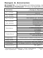
Ideal Test-Pro Digital Multimeter Mode d'emploi
- Catégorie
- Multimètres
- Taper
- Mode d'emploi
- Ce manuel convient également à
dans d''autres langues
Documents connexes
-
Ideal 61-763 Mode d'emploi
-
-
-
-
-
-
Ideal 61-797 Mode d'emploi
-
-
-
Autres documents
-
KRAFTWERK 31130 Mode d'emploi
-
Greenlee DM45 Le manuel du propriétaire
-
Amprobe PM51A Pocket Multimeter Manuel utilisateur
-
-
Greenlee DM-45 Digital Multimeter Manuel utilisateur
-
-
IDEAL INDUSTRIES 61-076 Guide d'installation
-
Beta 1760PA/AC Mode d'emploi
-
Innova 3310 Le manuel du propriétaire
-
CHAUVIN ARNOUX C.A. 6240 Double Retractable 10 A Test Probes Manuel utilisateur