Maico ESR 16-2 S Mounting And Operating Instructions
- Taper
- Mounting And Operating Instructions

Schallgedämmte Lüftungsbox
Sound-insulated ventilation box
Caisson d'air entrant insonorisé
ESR 12-2 ESR 12-2 S ESR 12-2 EC
ESR 16-2 ESR 16-2 S ESR 16-2 EC
ESR 20-2 ESR 20-2 S ESR 20-2 EC
ESR 25-2 ESR 25-2 S ESR 25-2 EC
ESR 31-2 ESR 31-2 S ESR 31-2 EC
ESR 35-2 DSR 35-2 S
ESR 40-2 DSR 40-2 S
Montage- und Betriebsanleitung
Mounting and Operating instructions
Instructions de montage et Mode d’emploi
www.maico-ventilatoren.com
D
GB
F

2
Schallgedämmte Lüftungsbox
1. Lieferumfang
Schallgedämmte Lüftungsbox inklusive
Klemmenkasten und Kabelverschraubung,
Montage- und Betriebsanleitung.
2. Verwendete Symbole
Warnsymbole 2.1
GEFAHR
Lebensgefahr.
Eine Nichtbeachtung kann
zum Tod oder zu schweren
Körperverletzungen führen.
WARNUNG
Verletzungsgefahr!
Eine Nichtbeachtung kann zu
schweren Körperverletzungen
führen.
VORSICHT
Verletzungsgefahr.
Eine Nichtbeachtung kann zu
leichten bis mittleren Körper-
verletzungen führen.
Sonstige Symbole 2.2
INFO-Symbol: Mit diesem
Symbol versehene Text-
passagen geben Ihnen wichtige
Informationen und Tipps.
● Aufzählungssymbol:
Liste mit wichtigen Informatio-
nen zum jeweiligen Thema.
Handlungssymbol:
Liste mit durchzuführenden
Tätigkeiten. Führen Sie die
angegebenen Anweisungen
der Reihe nach durch.
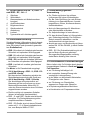
3. Produktinformationen
● ESR.. S und DSR.. S-Geräte mit
herausschwenkbarem Ventilator.
● ESR.. EC-Geräte mit herausschwenk-
barem Ventilator.
● ESR..-Geräte mit fest verschraubtem
Ventilator.
Impressum: © Maico Elektroapparate-Fabrik GmbH.
Deutsche Original-Betriebsanleitung.
Druckfehler, Irrtümer und technische Änderungen
vorbehalten.
i
●
D

3
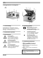
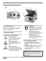
Geräteübersicht ESR.. S, DSR.. S 3.1
und ESR.. EC, Abb. A
1 Gehäuse
2 Winkelblech
3 Klemmenkasten mit Kabelverschrau-
bung(en)
4 Anschlussstutzen
5 Bügelverschluss
6 Gehäusedeckel
7 Abdeckung
8 Laufrad
T Typenschild mit Luftrichtungspfeil
Produktbeschreibung 3.2
Schallgedämmte Lüftungsbox, durch doppel-
wandiges, schallgedämmtes Gehäuse sehr
leise. Mit statisch und dynamisch gewuchte-
tem Radiallaufrad:
● ESR.. S-Laufrad mit rückwärts gekrümmten
Schaufeln mit optimalem Wirkungsgrad.
● DSR.. S-Laufrad mit rückwärts gekrümmten
Schaufeln mit optimalem Wirkungsgrad.
● ESR.. EC-Laufrad mit rückwärts gekrümm-
ten Schaufeln mit optimalem Wirkungsgrad.
● ESR..-Laufrad mit vorwärts gekrümmt
en
S
chaufeln.
Der Motor ist für Dauerbetrieb ausgelegt.
● 230 V-Ausführung = ESR.. S-, ESR.. EC-
und ESR..-Geräte
Bei thermischer Überlastung schaltet der
Motorüberlastungsschutz das Gerät aus.
● 400 V-Ausführung = DSR.. S-Geräte
Die Anschlüsse sind potenzialfrei auf
Klemmen geführt und müssen an ei
nen
Motorvollschutzschalter Maico MV 25
oder den Steuerstromkreis eines Schützes
angeschlossen werden.
● Ein/Aus erfolgt mit separatem Schalter
(dieser ist bauseitig bereitzustellen).
● ESR.. S- und ESR..-Geräte sind drehzahl-
steuerbar. Für Drehzahlsteuerung si
ehe
em
pfohlenes Maico-Zubehör.
● ESR.. EC-Geräte sind mit einem Potentio-
meter mit 0…10 V-Signal drehzahlsteuer-
bar, zum Beispiel Maico ST-EC.
Bestimmungsgemäße 3.3
Verwendung
● Zur Förderung kleiner bis mittlerer
Luftmengen bei hohen Widerständen.
● Zur Be- oder Entlüftung (je nach Einbau-
richtung) von Gewerberäumen, Ausstel-
lungsräumen, Büros, Konferenzräumen,
Umkleidekabinen.
● Auch als Absauganlage für Maschinen-
oder Arbeitsplätze einsetzbar.
● Zur Aufputzmontage in Innenräumen.
● Für den direkten Einbau in Lüftungsleitun-
gen. Einbaulage beliebig. Der Gehäuse-
deckel muss sich abnehmen und di
e
Ventilatoreinheit reinigen lassen.
● Anschluss saug- und druckseitig mit Nenn-
weiten DN 125 bis DN 400, je nach Geräte-
variante.
● ESR.. EC: Die Drehzahleinstellung ist mit
den im Maico-Sortiment gelistet
en
S
teuergeräten/Regelgeräten zulässig,
siehe Maico-Katalog oder Internet.
Vorhersehbare Fehlanwendungen 3.4
Maico haftet nicht für Schäden durch bestim-
mungswidrigen Gebrauch. Gerät auf keinen
Fall einsetzen:
● zur Förderung fetthaltiger Luft.
● bei verstopfter Ansaugöffnung oder
verstopftem Leitungsstrang.
● in der Nähe von brennbaren Materialien,
Flüssigkeiten oder Gasen.
● zur Förderung von Chemikalien,
aggressiven Gasen oder Dämpfen.
● in explosionsgefährdeten Bereichen.
● in Kombination mit Frequenzumrichter.
D

4
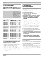
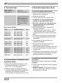
4. Technische Daten
Bemessungsspannung
ESR.. S, ESR.. EC, ESR
DSR.. S
230 V AC
400 V, 3 Ph + PE
Netzfrequenz
50 Hz
Schutzart
IP X4 bei
geschlossenem
Gehäusedeckel und
Einbau in Lüftungs-
leitungen mit
mindestens 1 m
Rohr auf der Saug-
und Druckseite
Abmessungen, Gewicht
Type
L x B x H in mm
kg
ESR 12-2 S
ESR 16-2 S
ESR 20-2 S
ESR 25-2 S
ESR 31-2 S
384 x 383 x 232
466 x 482 x 287
466 x 482 x 287
516 x 542 x 386
516 x 542 x 386
12
20
20
28
28
DSR 35-2 S
DSR 40-2 S
656 x 682 x 491
656 x 682 x 491
46
46
ESR 12-2 EC
ESR 16-2 EC
ESR 20-2 EC
ESR 25-2 EC
ESR 31-2 EC
380 x 380 x 230
380 x 380 x 230
380 x 380 x 285
480 x 460 x 285
510 x 540 x 385
12
12
20
18
26
ESR 12-2
ESR 16-2
ESR 20-2
ESR 25-2
ESR 31-2
384 x 383 x 232
384 x 383 x 232
384 x 383 x 286
480 x 460 x 285
510 x 340 x 385
12
12
20
18
26
DSR 35-2
DSR 40-2
656 x 682 x 491
656 x 682 x 491
46
46
5. Umgebungsbedingungen und
Grenzen für den Betrieb
● Zulässige Höchsttemperatur des Förder-
mediums: Je nach Gerätevariante
45 °C ... 65 °C, siehe Typenschild.
● Bei Betrieb mit raumluftabhängigen Feuer-
stätten muss für ausreichende Zuluftnach-
strömung gesorgt werden. Die maximal
zulässige Druckdifferenz pro Wohneinheit
beträgt 4 Pa.
6. Grundlegende
Sicherheitshinweise
Allgemeine Sicherheitshinweise 6.1
● Betriebsanleitung vor Inbetriebnahme
aufmerksam durchlesen.
● Anleitung aufbewahren.
● Das Gerät darf nicht als Spielzeug
ver
wendet werden.
● Montage nur durch Fachkräfte zulässig.
● Elektrischer Anschluss und Repara-
turen nur durch Elektrofachkräfte
zulässig.
● Gerät nur an einer fest verlegten
elektrischen Installation anschließen.
– Zulässiger Leitungsquerschnitt 1,5 mm².
– Vorrichtung zur Trennung vom Netz mit
mindestens 3 mm Kontaktöffnung je Pol
erforderlich.
● Gerät nur mit auf Typenschild angegebe-
ner Spannung und Frequenz betreiben.
● Gerät nur komplett montiert betreiben.
● Gerät und Rohrleitung gegen Ansaugun
g
von
Fremdkörpern sichern.
● Nie ohne Schutzgitter bei freier Ansaug
ung
bet
reiben. Zum Beispiel Maico-Schutzgitter
SG montieren.
● Veränderungen und Umbauten am Gerät
sind nicht zulässig und entbinden Maic
o
von
jeglicher Gewährleistung und Haftung.
Sicheres und korrektes Verhalten 6.2
für den Betrieb
Bei Fehlverhalten besteht Verletzungsgefahr!
● Keine Gegenstände in den Luftkanal oder
das Gerät hineinstecken.
● Drehendes Laufrad. Nicht zu nahe an das
Gerät gehen, damit Haare, Kleidung oder
Schmuck nicht in das Gerät hineingezog
en
w
erden können.
D

5
7. Montagevorbereitungen
GEFAHR
Lebensgefahr durch
Stromschlag.
Netzsicherung ausschalten.
Wand, Decke oder Konsole 7.1
Hinweise
● Einbaulage beliebig. IP X4 nur bei Ei
nbau
in Rohrleitungen mit mindestens 1 m Rohr
auf der Saug- und Druckseite.
● Nur an Wänden, Decken oder Konsolen mit
ausreichender Tragkraft anbringen.
WARNUNG
Verletzungsgefahr durch
unzureichende Befestigung
der Lüftungsbox.
Ausreichend dimensioniertes
Befestigungsmaterial
bereitstellen.
Montageort festlegen. Ausreichend
Abstand zur Wand/Decke berücksichtigen,
so dass sich auch der Gehäusedeckel
abnehmen und die Ventilatoreinheit
herausnehmen lässt.
Netzleitung zum Montageort fest verlegen.
Lüftungsleitungen vorbereiten 7.2
Hinweise
● Nur zum Nenndurchmesser pass
ende
Wi
ckelfalzrohre verwenden. Zulässig si
nd
R
ohre DN 125, DN 160, DN 200, DN 250,
DN 315, DN 355 oder DN 400, je nac
h
Gerätevariante.
● Bei Betrieb in staubhaltiger Umgebu
ng
Luf
tfilter in die Lüftungsleitung einbauen,
z.
B
. Maico-TFE.
8. Montage
Lüftungsbox montieren 8.1
Lüftungsbox möglichst schwingungs-
entkoppelt zum Rohrsystem montie-
ren, z. B. mit elastischer Manschette
Maico-EL und Schwingungsdämpfern.
Im Bereich des Montageortes für ei
nen
ebe
nen Untergrund sorgen.
Position der 4 Befestigungsbohrung
en
anz
eichnen und Bohrungen anbringen.
Bei abgehängten Rohrsystemen Montage-
träger mit ausreichender Tragkraft
anbringen.
Lüftungsbox fest mit der Wand, Decke,
Konsole oder dem Montageträger ver-
schrauben (geeignetes Befestigungs-
material ist bauseitig bereitzustellen).
Luftrichtungspfeil auf dem
Typenschild beachten.
Zulässige Wickelfalzrohre montieren un
d
di
ese mit elastischen Manschetten befes-
tigen.
Elektrischer Anschluss 8.2
GEFAHR
Lebensgefahr durch
Stromschlag.
Netzsicherung ausschalten.
Warnschild gegen versehent-
liches Wiedereinschalt
en
anbr
ingen.
Anschlussleitung zwischen Netz und
Klemmenkasten [3] muss fest verlegt
sein.
Spannungssteuerbare Ventilatoren
dürfen im Dauerbetrieb minimal mit
halber Nennspannung betrieben
werden. Wird dies nicht beachtet,
kann es zu Schäden an der
Motoreinheit kommen.
D
i
i
i
i
i
i

6
Klemmenkastendeckel entfernen.
VORSICHT
Kurzschlussgefahr durch
Nässe bei nicht ordnungs-
gemäßer Einführung der
Netzleitung.
Netzleitung ordnungsgemäß
durch Kabelverschraubung
f
ühren und anziehen.
Netzleitung so in den Klemmenkasten [3]
einführen, dass die Kabelverschraubu
ng
di
e Netzleitung dicht umschließt.
Bei ESR.. EC-Geräten ein zulässiges
Steuergerät/Regelgerät anschließen,
siehe Maico-Katalog oder Internet.
Zur Drehzahleinstellung an ESR.. EC-
Geräten am Potentiometer eine Mindest-
spannung von 0,5 V einstellen, damit der
Ventilatormotor starten kann.
Spannungen kleiner 0,5 V werden als
Stoppsignal gewertet.
Netzleitung an der Anschlussklemme im
Klemmenkasten [3] gemäß Schaltbil
d
ans
chließen, siehe Kapitel 14.
Klemmenkastendeckel anbringen und mit
den 4 Schrauben verschrauben.
Inbetriebnahme 8.3
Vor Inbetriebnahme sicherstellen, dass
sich keine Gegenstände, Kleinteile,
Verunreinigungen etc. in den Lüftungs-
leitungen befinden.
Übereinstimmung mit den technisc
hen
D
aten kontrollieren, siehe Typenschild.
Sicherstellen, dass die Luft ungehindert
strömen kann.
Lüftungsbox mit separatem Ein/Aus-
Schalter einschalten.
Ruhigen Lauf des Ventilator-Laufrades
prüfen.
9. Wartung
Das Gerät ist wartungsfrei.
10. Reinigung
ESR.. S, ESR.. EC und DSR.. S-Geräte:
Der Ventilator lässt sich zum Reinigen
herausschwenken.
GEFAHR
Lebensgefahr durch
Stromschlag.
Netzsicherung ausschalten
und S
tillstand des Laufrades
abwarten.
Beide Bügelverschlüsse [4] löse
n und
G
ehäusedeckel [6] abnehmen.
Beide Befestigungsschrauben der
Abdeckung [7] entfernen.
WARNUNG
Verletzungsgefahr durch
herausschwenkende
Ventilatoreinheit bei Einbau
im Bereich der Decke.
Ventilatoreinheit nach
E
ntfernen der Befestigungs-
schrauben vorsichti
g und
l
angsam ablassen.
Bei Montageort in Kopfhöhe
den ei
genen Standort
außerhalb des Schwenk-
bereichs wählen. Dies gilt
insbesondere, wenn Sie ein
e
Lei
ter benutzen.
Ventilatoreinheit [8] herausschwenken.
Gerät mit angefeuchtetem Tuch reinigen,
gegebenenfalls aussaugen!
Abdeckung [7] befestigen.
Gehäusedeckel [6] anbringen und mit
beiden Bügelverschlüssen [4] befestigen.
i
D

7
11. Störungsbehebung
● Bei jeder Störung eine Elektrofachkraft
hinzuziehen.
● Reparaturen sind nur durch Elektrofach-
kräfte zulässig.
GEFAHR
Lebensgefahr durch
Stromschlag.
Netzsicherung ausschalten
und Warnschild gegen
unbeabsichtigtes Wieder-
einschalten anbringen.
Störung Maßnahme
Gerätestillstand Prüfen, ob die Netzsiche-
rung eingeschaltet ist.
Thermischer
Überlastungs-
schutz schaltet
Gerät aus.
Vor Wiederinbetriebnahme
den Ventilator so lange
ausschalten, bis Motor und
Temperaturbegrenzer
abgekühlt sind. Erst dann
wieder einschalten.
Die Abkühlzeit kann je
nach Größe und Tempe-
raturverhältnissen bis zu
10 Minuten betragen.
Besteht die Störung
weiterhin, Elektrofachkraft
hinzuziehen.
Leistungs-
reduzierung
durch Unwucht
des Laufrades.
Fachkraft hinzuziehen.
Ablagerungen
am Laufrad und
im Gehäuse
durch staub-
haltige Luft.
Fachkraft hinzuziehen.
Luftfilter in Rohrsystem
einbauen.
Innenraum auf keinen Fall
mit Wasser oder Hoch-
druckreiniger reinigen!
Laufrad dreht
sich nicht.
Gerät ausschalten.
Sicherstellen, dass das
Laufrad nicht durch
Fremdkörper blockiert ist.
12. Demontage
GEFAHR
Lebensgefahr durch
Stromschlag.
Netzsicherung ausschalten.
Die Demontage ist nur durch
Elektrofachkräfte zulässig.
13. Entsorgung
Nicht in den Restmüll !
Das Gerät enthält teils wiederver-
wertbare Stoffe, teils Substanzen,
die nicht in den Restmüll gelangen
dürfen.
Entsorgen Sie das Gerät nach Ablauf
seiner Lebensdauer nach den in Ihrem
Land geltenden Bestimmungen.
i
i
D

8
Sound-insulated ventilation box
1. Scope of delivery
Sound-insulated ventilation box including
terminal box and cable screw-connections,
mounting and operating instructions.
2. Symbols used
Warning symbols 2.1
DANGER
Danger to life.
Non-observance can lead to
death or serious bodily injuries.
WARNING
Danger of injury.
Non-observance can lead to
serious bodily injuries
CAUTION
Danger of injury.
Non-observance can lead to
minor or more serious bodily
injuries.
Other symbols 2.2
INFO symbol:
Text passages marked with this
symbol contain important
information and tips.
● List symbol:
List containing important infor-
mation on the relevant subject.
Action symbol:
List of work to be carried out.
Follow the instructions in the
order given.
3. Product information
● ESR.. S and DSR.. S units with fan which
can be swung out.
● ESR.. EC units with fan which can be
swung out.
● ESR.. units with permanently screwed
down fan.
Acknowledgements
© Maico Elektroapparate-Fabrik GmbH.
This instruction is a translation of the German
original operating instructions. We cannot be
held responsible for mistakes or printing errors
and retain the right to make technical
modifications without giving prior notice.
GB
i

9
Equipment overview ESR.. S 3.1
and DSR.. S unit, Fig. A
1 Housing
2 Angle plate
3 Terminal box with cable screw-
connections
4 Coupling
5 Clip-locks
6 Housing cover
7 Cover
8 Impeller
T Rating plate with air direction arrow
Product description 3.2
Sound-insulated ventilation box. Very quiet
operation, thanks to double-wall, sound
insulated housing. With statically and
dynamically balanced centrifugal impeller:
● ESR.. S impeller with blades folded back-
wards for optimum efficiency.
● DSR.. S impeller with blades folded back-
wards for optimum efficiency.
● ESR.. EC impeller with blades folded back-
wards for optimum efficiency.
● ESR.. impeller with blades folded forwards.
The motor is designed for continuous
operation.
● 230 V model = ESR.. S, ESR.. EC a
nd
ESR
.. units
In the event of thermal overload, the motor
overload protection switches the unit off.
● 400 V model = DSR.. S units
Potential-free terminal connections, whic
h
m
ust be connected to a Maico MV
25
pr
otective motor switch or the control circuit
of a contactor.
● On and Off is to be carried out usi
ng a
s
eparate switch (this should be suppli
ed
by t
he customer).
● ESR.. S and ESR.. units are s
peed
c
ontrollable. See recommended Maic
o
ac
cessories for speed control.
● ESR.. EC units are speed controllable
through a 0...10 V signal potentiometer,
e.g. Maico ST-EC.
Intended use 3.3
● Supply of small to medium air volumes at
high resistances.
● For ventilation or air extraction (dependi
ng
on i
nstallation direction) of commercial
premises, showrooms, offices, conferenc
e
rooms, changing rooms.
● Can also be used as air extraction system
for machine areas or workspaces.
● For surface mounting indoors.
● For direct installation in ventilation ducts.
Any installation position. It must be
possible for the housing cover to be
removed and the fan unit to be cleaned.
● Connection on the inlet and outlet side wit
h
nom
inal sizes Ø 125 to Ø 400, dependin
g
on uni
t type.
● ESR.. EC: Speed setting is allowed wit
h
t
he control units listed in the current Maic
o
r
ange; see Maico catalogue or the Internet.
Predictable misuses 3.4
Maico is not liable for damages caused by
use contrary to the intended purpose.
Under no circumstances should the unit
be used:
● for conveying greasy air.
● if the intake opening or ducts are blocked.
● close to flammable materials, liquids or
gases.
● for conveying chemicals, aggressive gases
or vapours.
● in areas subject to explosion hazards.
● in combination with a frequency converter.
GB

10
4. Technical data
Rated voltage
ESR.. S, ESR.. EC,
ESR DSR.. S
230 V AC
400 V, 3 Ph + PE
Power frequency
50 Hz
Degree of protection
IP X4 degree of
protection with closed
housing cover and
when installed in ven-
tilation ducts with at
least 1 m of duct on
the inlet and outlet
sides
Dimensions, Weight
Type
L x W x H in mm
kg
ESR 12-2 S
ESR 16-2 S
ESR 20-2 S
ESR 25-2 S
ESR 31-2 S
384 x 383 x 232
466 x 482 x 287
466 x 482 x 287
516 x 542 x 386
516 x 542 x 386
12
20
20
28
28
DSR 35-2 S
DSR 40-2 S
656 x 682 x 491
656 x 682 x 491
46
46
ESR 12-2 EC
ESR 16-2 EC
ESR 20-2 EC
ESR 25-2 EC
ESR 31-2 EC
380 x 380 x 230
380 x 380 x 230
380 x 380 x 285
480 x 460 x 285
510 x 540 x 385
12
12
20
18
26
ESR 12-2
ESR 16-2
ESR 20-2
ESR 25-2
ESR 31-2
384 x 383 x 232
384 x 383 x 232
384 x 383 x 286
466 x 482 x 287
516 x 542 x 386
12
12
20
18
26
DSR 35-2
DSR 40-2
656 x 682 x 491
656 x 682 x 491
46
46
5. Environmental conditions and
operating limits
● Maximum permitted temperature of the
ai
r medium: Depends on unit variant
45 °C...65 °C, see rating plate.
● Sufficient supply air intake must be en-
sured during operation with air-ventilat
ed
f
ireplaces. The maximum permitt
ed
pr
essure difference per living unit is 4 Pa.
6. Essential safety instructions
General safety instructions 6.1
● Read the operating instructions through
c
arefully before starting up.
● Keep the instructions.
● The unit should not be used as a toy.
● Installation is only permitted whe
n
car
ried out by trained specialists.
● Electrical connections and repairs ar
e
onl
y permitted when carried out by
trained specialists.
● Only connect the unit to a permanent
electrical installation.
– Permitted cable cross section: 1.5 mm²
– Mains isolation device required wit
h
c
ontact openings of at least 3 mm at eac
h
pol
e.
● The fan unit may only be operated usi
ng
t
he voltage and frequency shown on the
rating plate.
● Only operate the fan unit when it is
completely installed.
● Ensure that foreign bodies cannot
be
s
ucked into the unit and duct.
● Never operate without protective grille with
f
ree inlet. For example, fit a Maico protec-
tive grille SG.
● Modifications and alterations to the unit ar
e
not permitted and release Maico from any
guarantee obligations and liability.
Safe and correct practices during 6.2
operation
In the case of incorrect use there is the risk
of injury!
● Do not insert any objects in the air channel
or the unit.
● Rotating impeller. Do not get too close t
o
t
he unit, to avoid hair, clothing or jeweller
y
bei
ng drawn into the unit.
GB

11
7. Installation preparation
DANGER
Danger to life from electric
shock.
Switch the mains fuse off.
Wall, ceiling or bracket 7.1
Notes
● Any installation position. IP X4 only when
installed in ducts with at least 1 m of duct
on the suction and pressure sides.
● Only install on walls, ceilings or brackets
with sufficient load-bearing capacity.
WARNING
Danger of injury from failure
to mount ventilation box
securely.
Make sure you use mounting
material, which is sized for the
purpose.
Decide on the installation location. Make
sure there is sufficient distance to the
wall/ceiling so that the housing cover and
the fan unit can also be removed.
Lay a permanent power cable to the
installation location.
Preparing the ventilation ducts 7.2
Notes
● Only use folded spiral-seams ducts that
match the nominal diameter. Ø 125,
Ø 160, Ø 200, Ø 250, Ø 315, Ø 355 or
Ø 400 ducts are permitted, depending on
unit type.
● Install an air filter in the ventilation duct,
e.g. Maico TFE if operating the unit in a
dusty environment.
8. Installation
Fitting ventilation box 8.1
As far as possible, install the
ventilation box such that there is no
transfer of vibrations to the duct
system, e.g. by using Maico EL
flexible cuffs and vibration dampers.
Make sure there is a level surface at the
installation location.
Mark the position of the 4 mounting holes
and make the holes.
For suspended duct systems, fit a
mounting support with sufficient load-
bearing capacity.
Screw the ventilation box permanently to
the wall, ceiling, bracket or mounting
support using suitable mounting material
to be supplied by the customer.
Note air direction arrow on the
rating plate.
Fit permitted folded spiral-seams ducts and
secure with flexible cuffs
Electrical connection 8.2
DANGER
Danger to life from electric
shock.
Switch the mains fuse off.
Position a warning notice to
avoid the unit being acciden-
tally switched back on.
The cabling between the power and
the terminal [3] box must be
permanent.
Voltage controllable fans are
allowed to be used in continuous
operation with a minimum of half
of the nominal voltage. If this is
not complied with, it can cause
damage to the motor unit.
i
i
i
i
i
GB
i

12
Remove the terminal box cover.
CAUTION
Danger of short-circuits
caused by damp if the power
cable is not inserted correctly.
Guide power cable correctly
t
hrough cable screw-connec-
tions and tighten.
Insert the power cable into the terminal box
[3]
s
uch that the cable screw-connecti
on
f
its tightly round the power cable.
With ESR.. EC units connect a permitt
ed
c
ontrol unit; see Maico catalogue or t
he
I
nternet.
For speed setting at the ESR.. EC units set
a minimum voltage of 0.5 V at the poten-
tiometer so that the fan motor can start.
Voltages below 0.5 V are evaluated
as a stop signal.
Connect power cable to connecti
ng
t
erminal in terminal box [3] as shown i
n
w
iring diagram, see section 14.
Fit terminal box cover and screw down wit
h
4
screws.
Start-up 8.3
Before start-up, ensure that there are no
ob
jects, small parts, dirt, etc., in the ven-
tilation ducts.
Check that the technical data has
been
adh
ered to, by reference to the rating plate.
Ensure that the air can flow unhindered.
Switch on ventilation box with separat
e
on/off switch.
Check that the fan impeller is runni
ng
qui
etly.
9. Maintenance
The unit is maintenance-free.
10. Cleaning
● ESR.. S, ESR.. EC and DSR.. S units:
The fan can be swung out for cleaning.
DANGER
Danger to life from electric
shock.
Switch off the mains fuse and
w
ait for the impeller to stop.
Loosen both clip-locks [4] and remove t
he
hous
ing cover [6].
Remove both fixing screws from cover [7].
WARNING
Danger of injury from fan unit
swinging out if fitted near
ceiling.
Once you have removed the
f
ixing screws, carefull
y and
s
lowly lower the fan unit.
If the installation location is at
head height, select a location
out
side the unit's swing area.
This applies particularly w
hen
us
ing a ladder.
Swing the fan unit [8] out.
Clean the unit with a damp cloth, suck dr
y
i
f necessary.
Secure cover [7].
Attach the housing cover [6] and secur
e
w
ith the two clip-locks [4].
i
GB

13
11. Fault rectification
● Call on the services of a trained
electrician any time there is a fault.
● Repairs should only be carried out
by a trained electrician.
DANGER
Danger to life from electric
shock.
Switch off mains fuse and
han
g up warning notice t
o
pr
event it from accidentall
y
being started up again.
Fault Countermeasure
Unit doesn’t run
Check that the mains fuse is
switched on.
Impeller not
turning.
Switch off unit. Ensure that
the impeller is not blocked
by foreign bodies.
Thermal
overload
protection
switches the
unit off.
Before recommissioning,
switch the fan off long
enough for the motor and
temperature limiter to cool.
Only then switch back on.
Depending on size and
current temperature, it may
take up to 10 minutes to
cool down.
If the fault still continues, call
on the services of a trained
electrician.
Performance
reduction
caused by
imbalance of the
impeller.
Call on the services of a
trained specialist.
Deposits on the
impeller and in
the housing
caused by dust
in the air.
Call on the services of a
trained specialist.
Install an air filter in the
ducting.
Under no circumstances
should the inside of the unit
be cleaned with water or a
high-pressure cleaner.
12. Dismantling
DANGER
Danger to life from electric
shock.
Switch the mains fuse off.
Dismantling should only be carried
out by a trained electrician.
13. Disposal
Do not dispose of in domestic
waste.
The unit contains in part material that
can be recycled and in part
substances that should not end up as
domestic waste.
Dispose of the unit once it has reached the
end of
its working life according to t
he
r
egulations valid where you are.
i
i
GB

14
Caisson d'air entrant insonorisé
1. Éléments fournis
Caisson d'air entrant insonorisé y compris
boîte à bornes et passe-câble, notice de
montage et d'utilisation.
2. Symboles utilisés
Symboles d'avertissement 2.1
DANGER
Danger de mort !
Le non respect peut entraîner
des blessures corporelles
graves, voire la mort.
AVERTISSE-
MENT
Risque de blessure !
Le non-respect peut entraîner
des blessures corporelles
graves.
PRUDENCE
Risque de blessure !
Le non respect des symboles
d'aver-tissement peut entraîner
des blessures corporelles légères
à moyennement graves.
Autres symboles 2.2
Symbole INFO : les passages
accompagnés de ce symbole
fournissent des informations et
conseils importants.
● Symbole d'énumération :
liste d’informations importantes
relatives au sujet concerné.
Symbole d'action :
liste indiquant des actions à
exécuter. Suivez les instructions
dans l'ordre indiqué.
3. Informations produit
● Les appareils ESR.. S et DSR.. S sont
équipés d'un ventilateur orientable vers
l'extérieur.
● Les appareils ESR.. EC sont équipés d'un
ventilateur orientable vers l'extérieur.
● Les appareils ESR.. sont équipés d'un
ventilateur vissé.
i
Mentions légales : © Maico Elektroapparate
Fabrik GmbH. Cette instruction est une traduction
de l'instruction allemande originale. Sous réserve
de fautes d'impression, d'erreurs et de modifica-
tions techniques.
F

15
Vue d’ensemble de l’appareil 3.1
ESR.. S, DSR.. S et ESR.. EC, Fig. A
1 Boîtier
2 Cornière
3 Boîte à bornes avec passe-câble
4 Pièces de raccordement
5 Clip de fermeture
6 Couvercle du boîtier
7 Cache de protection
8 Turbine
T Plaque signalétique avec flèche de
direction de l'air
Description du produit 3.2
Caisson d'air entrant insonorisé, très silen-
cieux grâce au boîtier insonorisé à paroi
double. Turbine radial à équilibrage statique
et dynamique :
● Turbine ESR.. S avec pales courbées en
arrière, avec rendement optimal.
● Turbine DSR.. S avec pales courbées en
arrière, avec rendement optimal.
● Turbine ESR.. EC avec pales courbées en
arrière, avec rendement optimal.
● Turbine ESR.. avec pales courbées vers
l'avant.
Le moteur est conçu pour un fonctionnement
continu.
● Modèle 230 V = Appareils ESR.. S, ESR..
EC et ESR..
En cas de surcharge thermique, le disposi-
tif de sécurité contre les surcharges met le
moteur hors service.
● Modèle 400 V = Appareils DSR.. S
Les branchements sont amenés par
contacts secs sur des bornes et doivent
être raccordés à un disjoncteur-protecteur
moteur Maico MV 25 ou au circuit
électrique de commande d'un contacteur.
● Commande Marche/Arrêt par interrupteur
séparé (à fournir par le client).
● Il est possible de commander le régime
des appareils ESR.. S et ESR... Pour la
régulation du régime, voir les accessoires
Maico recommandés.
● La vitesse des appareils ESR.. EC, du
Maico ST-EC par exemple, est comman-
dée par un potentiomètre à signal 0…10 V.
Utilisation conforme 3.3
● Refoulement de débits d'air faibles à
moyens en présence de résistances
élevées.
● Pour ventilation en entrée ou sortie (selon
la direction du montage) d'ateliers, de
bureaux, de salles de conférence, de
cabines d'essayage.
● Également utilisable comme installation
d'aspiration pour les salles de machines ou
les salles de travail.
● Pour montage apparent dans les pièces
intérieures.
● Pour un montage direct dans les conduits
d'air. Position de montage au choix. On
doit pouvoir retirer le couvercle du boîtier
pour nettoyer l'unité de ventilateur.
● Raccord côté air aspiré et air comprimé
d'une largeur nominale Ø 125 à Ø 400,
en fonction de la variante d'appareil.
● ESR.. EC : Le réglage de la vitesse de
rotation est autorisé au moyen des unités
de commande/régulateurs énumérés dans
la gamme Maico, cf. catalogue Maico ou
Internet.
Erreurs d’applications prévisibles 3.4
Maico décline toute responsabilité en cas de
dommages résultant d'une utilisation non
conforme. Ne jamais utiliser l'appareil :
● pour le refoulement d'air contenant des
graisses.
● en cas d'ouverture d'aspiration ou de
conduit bouché.
● à proximité de matières, liquides ou gaz
inflammables.
● pour l'acheminement de produits
chimiques, de gaz ou de vapeurs agressifs.
● dans des zones explosibles.
● en combinaison avec un convertisseur de
puissance.
F

16
4. Caractéristiques techniques
Tension de service
ESR.. S, ESR.. EC, ESR
DSR.. S
230 V AC
400 V, 3 Ph + PE
Fréquence du secteur
50 Hz
Type de protection
IP X4 avec
couvercle de boîtier
fermé et insertion
dans les conduites
de ventilation avec
tuyau d'au moins de
1 m côté aspiration
et pression
Dimensions, Poids
Type
L x l x H à mm
kg
ESR 12-2 S
ESR 16-2 S
ESR 20-2 S
ESR 25-2 S
ESR 31-2 S
384 x 383 x 232
466 x 482 x 287
466 x 482 x 287
516 x 542 x 386
516 x 542 x 386
12
20
20
28
28
DSR 35-2 S
DSR 40-2 S
656 x 682 x 491
656 x 682 x 491
46
46
ESR 12-2 EC
ESR 16-2 EC
ESR 20-2 EC
ESR 25-2 EC
ESR 31-2 EC
380 x 380 x 230
380 x 380 x 230
380 x 380 x 285
480 x 460 x 285
510 x 540 x 385
12
12
20
18
26
ESR 12-2
ESR 16-2
ESR 20-2
ESR 25-2
ESR 31-2
384 x 383 x 232
384 x 383 x 232
384 x 383 x 286
466 x 482 x 287
516 x 542 x 386
12
12
20
18
26
DSR 35-2
DSR 40-2
656 x 682 x 491
656 x 682 x 491
46
46
5. Conditions ambiantes et limites
d'utilisation
● Température maximale admissible du
fluide refoulé : en fonction de la variante
de l
'appareil 45...65 °C, voir plaque signal-
étique.
● Lors d'une utilisation avec des foyers
dépendants de l'air ambiant, il faut veiller à
une arrivée d'air suffisante. La différence
de pr
ession maximale par unité d'habitati
on
es
t de 4 Pa.
6. Consignes de sécurité
fondamentales
Consignes de sécurité générales 6.1
● Lire attentivement le mode d'emploi avant
la mise en service.
● Conserver la notice.
● L’appareil ne doit pas être utilisé comme
j
ouet.
● Montage exclusivement réservé au
x
p
rofessionnels.
● Le branchement électrique et les répa-
rations sont exclusivement réservé
s à
d
es électriciens qualifiés.
● Ne raccorder l'appareil qu'à une installation
bi
en fixée.
– Diamètre de câble autorisé : 1,5 mm².
– Dispositif de coupure du réseau avec
au
m
oins une ouverture de contact nécessair
e
de 3 m
m par pôle.
● Utiliser exclusivement l'appareil à la ten-
sion et à la fréquence indiquées sur la
plaque signalétique.
● N’utiliser l’appareil qu’après son montag
e
complet.
● Sécuriser l'appareil et le conduit contr
e
l
'aspiration de corps étrangers.
● Ne jamais faire fonctionner l'appareil sans
grille de protection en cas d'aspiration libre.
Monter par exemple une grille de protec-
tion Maico SG.
● Les modifications et transformations
apportées à l’appareil de ventilation sont
rigoureusement interdites et dégagent
Maico de toute responsabilité ou garantie.
F

17
Comportement sûr et correct lors 6.2
du fonctionnement
Risque de blessure en cas de mauvaise
manipulation !
● Ne pas introduire d'objet dans la gaine
d'aération ou dans l'appareil.
● Rotation de la turbine. Ne pas s’appro-
cher trop près de l’appareil afin d’éviter
que
des
cheveux, des vêtements ou des bijoux
ne s’y coincent.
7. Préparation au montage
DANGER
Risque d’électrocution.
Mettre le fusible secteur hors
service.
Mur, plafond ou console 7.1
Remarques
● Position d'installation au choix. Type
de
protection IP X4 uniquement lors d'un mon-
tage en conduit avec conduit d'au moins
1 m du côté air aspiré et air comprimé.
● Uniquement sur les murs, plafonds
ou
c
onsoles présentant une force portant
e
suffisante.
AVERTIS-
SEMENT
Risque de blessure en cas
de fixation insuffisante du
caisson d'air entrant.
Prévoir du matériel de fixation
de dimension suffisante.
Déterminer le lieu d'installation. Garantir
une distance suffisante par rapport
au
m
ur/plafond, de façon à ce qu'il soit
possible de retirer le couvercle du boîtier
et l'unité de ventilation.
Poser le câble secteur sur le lieu d'in-
stallation.
Préparation des gaines d'air 7.2
Remarques
● Utiliser uniquement des tuyaux agrafés
adaptés au diamètre nominal. Les tuyaux
Ø 125, Ø 160, Ø 200, Ø 250, Ø 315, Ø 35
5
ou Ø
400 sont autorisés, en fonction de l
a
variante d'appareil, sont admis.
● En cas de fonctionnement dans un envi-
ronnement chargé de poussières, monter
un filtre à air sur la gaine d'air, comme par
ex. Maico-TFE.
8. Montage
Montage du caisson d'air entrant 8.1
Monter le caisson d'air entrant sur le
système à gaine ronde en l’isolant le
plus possible contre les vibrations, via
une manchette élastique Maico-EL
par ex., et des plots anti-vibrations.
Assurer un support plan sur le lieu
d’
installation.
Tracer l'emplacement des 4 trous
de
f
ixation et percer les trous.
En cas de systèmes à gaine ronde, utiliser
un support de montage avec une forc
e
por
tante suffisante.
Visser le caisson d'air sortant sur le mur, l
e
pl
afond, la console ou le support de
montage (préparer le matériau de fixation
côté œuvre de manière adéquate).
Respecter la flèche du sens de
l'air se trouvant sur la plaque
signalétique.
Monter la gaine agrafée autorisée et l
a
f
ixer avec des manchettes flexibles.
Branchement électrique 8.2
DANGER
Risque d’électrocution.
Mettre le fusible secteur hors
service.
Apposer un panneau d'aver-
tissement prévenant toute re-
mise en service intempestive.
i
i
i
i
F

18
Le conduit de raccordement qui
sépare le secteur de la boîte à bornes
[3] doit être bien fixé.
Les ventilateurs réglables en
tension doivent être exploités au
minimum avec une demi-tension
nominale en fonctionnement
continu. Un non-respect de cette
exigence peut endommager l'unité
motrice.
Retirer le couvercle de la boîte à bornes.
PRUDENCE
Risque de court-circuit en cas
d’humidité liée à une insertion
incorrecte du câble-secteur.
Mettre en place et tirer les
câbles secteur au travers de
passe-câble à vis.
Insérer le câble secteur dans la boîte à
bornes [3] de façon à ce que le passe-
câble à vis enserre fermement le câble
secteur.
Avec les appareils ESR.. EC, connecter
une unité de commande/un régulateur
autorisé, cf. catalogue Maico ou Internet.
Pour régler la vitesse de rotation des ap-
pareils ESR.. EC, sélectionner une tension
minimum de 0,5 V au potentiomètre
permettant le démarrage du moteur de
ventilateur.
Les tensions inférieures à 0,5 V sont
assimilées à un signal d'arrêt.
Raccorder le câbles secteur à la fiche de
la boîte à bornes [3] selon le schéma
électrique, voir chapitre 14.
Mettre le couvercle de la boîte à bornes en
place et le visser à l'aide des 4 vis.
Mise en service 8.3
Avant la mise en service, s’assurer que les
gaines d'air sont exemptes d’objets, de
petites pièces ou d’impuretés.
Contrôler la concordance avec les
caractéristiques techniques, cf. plaque
signalétique.
S’assurer que l’air peut circuler librement.
Allumer le caisson d'air entrant avec
l’interrupteur Marche/Arrêt séparé.
Vérifier le fonctionnement régulier de la
turbine du ventilateur.
9. Maintenance
L'appareil ne nécessite aucune maintenance.
10. Nettoyage
Appareils ESR.. S, ESR.. EC et DSR.. S:
Pour le nettoyage, sortir le ventilateur en
le basculant.
DANGER
Risque d’électrocution.
Mettre le fusible secteur hors
service et attendre jusqu'à ce
que la turbine soit à l'arrêt .
Desserrer les deux clips de fermeture [4] et
retirer le couvercle du boîtier [6].
Retirer les vis de fixation du couvercle [7].
AVERTIS-
SEMENT
Risque de danger par le
basculement vers l'extérieur
de l'unité de ventilation,
au niveau du couvercle, à
proximité du site d'intégration.
Extraire l'unité de ventilation
lentement et avec précaution
après avoir retiré les vis de
fixation.
Si le montage a lieu sur un
site situé à hauteur d'homme,
prendre en compte la zone de
basculement lors du choix du
site. Ceci est particulièrement
important si vous utilisez une
échelle.
Faire basculer l'unité de ventilation en la
basculant.
Nettoyer l'appareil avec un chiffon humi-
difié, aspirer éventuellement.
Fixez le revêtement [7].
Mettre en place le couvercle du boîtier [6]
et le fixer à l'aide des deux clips de ferme-
ture [4].
i
i
F
i

19
11. Élimination des défauts
● Lors de tout dysfonctionnement, con-
sulter un électricien.
● Les réparations sont exclusivement
réservées à des électriciens qualifiés.
DANGER
Risque d’électrocution.
Mettre le fusible secteur hors
service et mettre en place un
panneau d'avertissement pour
éviter une remise en marche
inopinée.
Dysfonction-
nement
Mesure
Arrêt de l'appareil
Vérifier que le fusible
secteur est enclenché.
La protection
thermique contre
les surcharges
met l'appareil à
l'arrêt.
Avant toute remise en
service, maintenir le
ventilateur à l'arrêt jusqu'à
ce que le moteur et le
limiteur de température
soient refroidis. Ne
procéder alors qu'à la
remise en service.
Le temps de refroidisse-
ment peut atteindre
10 minutes en fonction de
la taille et des tempéra-
tures ambiantes.
Si le dysfonctionnement
persiste, faire appel à un
électrotechnicien.
Baisse du rende-
ment lié à un
balourd de la
turbine.
Contacter un spécialiste.
Dépôts sur la
turbine et dans le
châssis dus à l’air
chargé de
poussières.
Contacter un spécialiste.
Monter le filtre à air dans
le système à gaine ronde.
Ne nettoyer en aucun cas
l'intérieur avec de l'eau ou
un nettoyeur à pression !
La turbine ne
tourne pas.
Mettre l'appareil à l’arrêt.
S’assurer que la turbine
n’est pas bloquée par des
corps étrangers.
12. Démontage
DANGER
Risque d’électrocution.
Mettre le fusible secteur hors
service.
Le démontage est exclusivement
réservé à des électriciens qualifiés.
13. Élimination
Ne pas mettre au rebut avec les
déchets ménagers.
L'appareil contient des matériaux
partiellement recyclables,
ne devant pas être mises au rebut
avec les déchets ménagers.
Éliminez l'appareil arrivé en fin de vie en
r
espectant les dispositions applicables
dans votre pays.
i
i
F

20
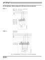
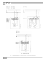
ESR.. S
DSR.. S
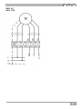
14. Schaltbilder / Wiring diagrams / Schémas de branchement
TW = Steuerstromkreis / Control circuit / Circuit de commande
D
F
GB
La page est en cours de chargement...
La page est en cours de chargement...
La page est en cours de chargement...
La page est en cours de chargement...
-
 1
1
-
 2
2
-
 3
3
-
 4
4
-
 5
5
-
 6
6
-
 7
7
-
 8
8
-
 9
9
-
 10
10
-
 11
11
-
 12
12
-
 13
13
-
 14
14
-
 15
15
-
 16
16
-
 17
17
-
 18
18
-
 19
19
-
 20
20
-
 21
21
-
 22
22
-
 23
23
-
 24
24


Maico ESR 16-2 S Mounting And Operating Instructions
- Taper
- Mounting And Operating Instructions
dans d''autres langues
- English: Maico ESR 16-2 S
- Deutsch: Maico ESR 16-2 S
Documents connexes
-
Maico ERH R Series Mounting & Operating Instructions
-
Maico ERH 10-04 Mounting And Operating Instructions
-
Maico EDR 31 Mounting And Operating Instructions
-
-
-
-
Autres documents
-
VOLTCRAFT LCR-300 Operating Instructions Manual
-
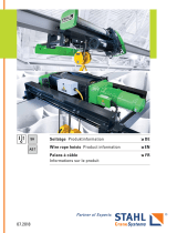 STAHL CraneSystems SH/AS Wire Rope Hoist Le manuel du propriétaire
-
Telit Wireless Solutions CE910-DUAL Hardware User's Manual
-
-
LG 37LC2RC Le manuel du propriétaire
-
Sames Turbine speed control Manuel utilisateur
-
Kampmann TOP unit heaters Guide d'installation
-
Kaldewei 7082 Manuel utilisateur
