
37854-0-0117 Page 1Empire Comfort Systems Inc. • Belleville, IL
INSTALLATION INSTRUCTIONS
PVSRT1-1 REMOTE
TEMPERATURE SENSOR KIT
FOR USE ON: PVS(18,35)(N,P)
INSTRUCTIONS MUST BE LEFT WITH THE OWNER FOR FUTURE REFERENCE AFTER INSTALLATION.
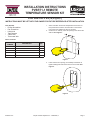
1. Select a location for Remote Temperature Sensor Kit. For
best performance select a central location in the heated
room away from drafts from doors or windows.
2. Create a 2 1/4” wide by 3 3/4” tall opening in the wall for the
wall box. See Figure 1.
Figure 1
3. Insert wall box into opening, use a Phillips screwdriver to
tighten holding tabs and secure the box into the wall. See
Figure 2.
Figure 2
Tools Needed:
• Phillips Screwdriver
• Flat Screwdriver
• Utility Knife
• Tape Measure
• 4 Wire Nuts
• Thermostat Wire
Carton Contents:
PART
NUMBER
DESCRIPTION QTY
R11712 Wall Box 1
R11713 Cover Plate 1
32331 Wall Bracket 1
R11710 Sensor Extension Harness 1
R11711 Wall Plate Harness 1

37854-0-0117Page 2 Empire Comfort Systems Inc. • Belleville, IL
4. Runthermostatwirefromthewallboxopeningtoaooror
wall opening beneath the left side of the wall furnace’s rear
shroud near the temperature sensor. Ensure enough wire
extends through the openings to make the connections. It
may be necessary to remove the wall furnace from the rear
shroud to create the thermostat wire opening and route the
thermostat wires.
5. Remove the wall furnace’s front panel and turn off gas and
power to the wall furnace. If the wall furnace needs to be
removed from the rear shroud, disconnect the wall furnace
from the gas line and venting. Remove the four screws se-
curing the rear shroud then move the wall furnace away from
the wall. See the venting section of the wall furnace installa-
tion instructions.
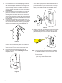
6. Connect two thermostat wires to the wire leads on the con-
nector harness assembly provided with this kit using two wire
nuts, note wire color. Route the end of the plug through an
upper slot in the side of the rear shroud. See Figure 3.
Figure 3
7. If the wall furnace has been removed from the rear shroud
move the wall furnace back into position and re-attach the
gas line and venting. Re-attach the rear shroud with the
screws removed in step 5. See the venting section of the
wall furnace installation instructions.
8.
Remove temperature sensor from wall furnace and
insert the wire harness connector. See Figure 4. Retain
temperature sensor.
Figure 4
9. At the wall box opening connect the two thermostat wires to
the two wire leads on the wall bracket assembly. Insert tem-
perature sensor from step 8 into the wall bracket assembly.
Insert the wall bracket assembly into the wall box opening.
See Figure 5.
Figure 5
10. Install the cover plate, the temperature sensor must protrude
through the hole in the center of the cover plate. The cover
plate screws will pass through the holes in the wall bracket
assembly and secure both to the wall box. See Figure 6.
Figure 6
NOTE: Thecoverplatemaybere-nishedpriortoinstallation
to match the room decor. The hole in the center of the
plate MUST remain clear for the temperature sensor to
function properly.
Caution:Ifre-nishingthecoverplateafterinstallation,DONOT
paint or cover the temperature sensor.
11. Turn power and gas to the wall furnace back on.

37854-0-0117 Page 1Empire Comfort Systems Inc. • Belleville, IL
INSTRUCTIONS D’INSTALLATION
TROUSSE DE SONDE DE
TEMPÉRATURE DISTANTE PVSRT1-1
À UTILISER SUR : PVS(18,35)(N,P)
LES INSTRUCTIONS DOIVENT ÊTRE LAISSÉES AU PROPRIÉTAIRE
POUR CONSULTATION ULTÉRIEURE APRÈS L’INSTALLATION.
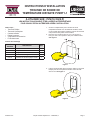
1. Choisir un emplacement pour la trousse de sonde
température distante. Pour les meilleurs résultats, choisir
un lieu central dans la pièce chauffée, à l’écart des courants
d’air provenant des portes ou des fenêtres.
2. Découperuneouverturede2-1/4pox3-3/4po(larg.x
haut.)(57mmx95mm)danslemurpourlaboîtemurale.
Voir Figure 1.
Figure 1
3. Insérerlaboîtemuraledansl’ouverture,utiliseruntournevis
Phillipspourserrerlespattesdexationetxerlaboîte
dans le mur. Voir Figure 2.
Figure 2
Outils requis :
• Tournevis Phillips
• Tournevis à lame plate
• Couteau utilitaire
• Ruban à mesurer
• 4 capuchons de connexion
• Fil de thermostat
Contenu de l’emballage
NUMÉRO
DE PIÈCE
DESCRIPTION QTÉ
R11712 Boîtemurale 1
R11713 Plaquedenitionmurale 1
32331 Support mural 1
R11710 Faisceau de rallonge de la sonde 1
R11711 Faisceaudelsdelaplaquemurale 1

37854-0-0117Page 2 Empire Comfort Systems Inc. • Belleville, IL
4. Acheminerleslsdethermostatdepuisl’oricedelaboîte
muralejusqu’auplancherouunoricedanslemursous
le côté gauche du capot arrière de l’appareil de chauffage
près de la sonde de température. S’assurer qu’une longueur
delsufsantedépassedesoricespoureffectuerles
connexions. Il peut s’avérer nécessaire d’enlever l’appareil
dechauffagemuralducapotarrièrepourdécouperl’orice
deslsduthermostatetacheminerleslsdethermostat.
5. Enlever le panneau frontal de l’appareil de chauffage et
couper l’alimentation électrique et en gaz de cet appareil.
Si l’appareil de chauffage doit être retiré du capot arrière,
déconnecter la conduite de gaz et le tuyau de ventilation à
l’appareil.Enleverlesquatrevisquixentlecapotarrière
puis déplacer l’appareil de chauffage à l’écart du mur. Voir la
section Ventilation des instructions d’installation de l’appareil
de chauffage mural.
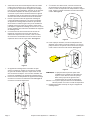
6. Connecterdeuxlsdethermostatauxlsdesortiedu
faisceau du connecteur fourni avec cette trousse en
utilisant deux capuchons de connexion, noter la couleur
del.Acheminerl’extrémitédelacheàtraverslafente
supérieure dans le côté du capot arrière. Voir Figure 3.
Figure 3
7. Si l’appareil de chauffage mural a été retiré du capot
arrière, le remettre en position et raccorder les conduites
de gaz et de ventilation. Reposer le capot arrière à l’aide
des vis enlevées à l’étape 5. Voir la section Ventilation des
instructions d’installation de l’appareil de chauffage mural.
8.
Enlever la sonde de température de l’appareil de chauffage
etinsérerleconnecteurdufaisceaudels.Voir Figure 4.
Conserver la sonde de température.
Figure 4
9. Àl’ouverturedelaboîtemurale,connecterlesdeuxls
dethermostatauxdeuxlsdesortiesurlesupportmural.
Insérer la sonde de température de l’étape 8 dans le support
mural.Insérerlesupportmuraldansl’ouverturedelaboîte
murale. Voir Figure 5.
Figure 5
10. Poserlaplaquedenition,lasondedetempératuredoit
dépasser du trou dans le centre de la plaque. Les vis de la
plaquedenitionvontpasseràtraverslestrousdusupport
muraletxerlesdeuxàlaboîtemurale.Voir Figure 6.
Figure 6
REMARQUE :Laplaquedenitionpeutêtreparéeavant
l’installation pour s’adapter à la décoration de
la pièce. Le trou dans le centre de la plaque
DOITresterpropreandegarantirlebon
fonctionnement de la sonde de température.
Attention:Sil’onparelaplaquedenitionavantl’installation,
NE PAS peindre ni recouvrir la sonde de température.
11. Rétablir l’alimentation électrique et de gaz à l’appareil de
chauffage mural.
-
 1
1
-
 2
2
-
 3
3
-
 4
4


Empire Comfort Systems PVSRT1-1 Le manuel du propriétaire
- Taper
- Le manuel du propriétaire
- Ce manuel convient également à
dans d''autres langues
Autres documents
-
Empire Heating Systems PVS35P-3 Le manuel du propriétaire
-
-
-
-
-
-
-
-
-