Sony VPL-FX51 Manuel utilisateur
- Catégorie
- Projecteurs de données
- Taper
- Manuel utilisateur
Ce manuel convient également à

2002 Sony Corporation
4-089-637-12 (1)
VPL-FX51
Operating Instructions
Mode d’emploi
Manual de instrucciones
FR
ES
Data Projector
GB
VPL-FX51

2 (GB)
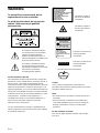
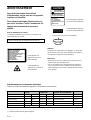
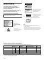
To prevent fire or shock hazard, do not
expose the unit to rain or moisture.
To avoid electrical shock, do not open the
cabinet. Refer servicing to qualified
personnel only.
This symbol is intended to alert the
user to the presence of uninsulated
“dangerous voltage” within the
product’s enclosure that may be of
sufficient magnitude to constitute a risk
of electric shock to persons.
This symbol is intended to alert the
user to the presence of important
operating and maintenance (servicing)
instructions in the literature
accompanying the appliance.
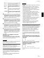
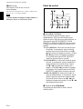
WARNING
This label is located on
the rear of the Remote
Commander.
This label is located on the
rear of the Remote
Commander.
Caution
Use of controls or adjustments or performance of
procedures other than those specified herein may result in
hazardous radiation exposure.
Notes
• Do not aim the laser at people or not look into the laser
transmitter.
• When the Remote Commander causes malfunction,
consult with qualified Sony personnel. We change the
Remote Commander as new one according to the
guarantee.
For the customers in Canada
This Class A digital apparatus complies with Canadian
ICES-003.
This label is located on the
rear of the Remote
Commander.
Laser light shines out of this window.
For the customers in the USA
This equipment has been tested and found to comply with
the limits for a Class A digital device, pursuant to Part 15 of
the FCC Rules. These limits are designed to provide
reasonable protection against harmful interference when the
equipment is operated in a commercial environment. This
equipment generates, uses, and can radiate radio frequency
energy and, if not installed and used in accordance with the
instruction manual, may cause harmful interference to radio
communications. Operation of this equipment in a
residential area is likely to cause harmful interference in
which case the user will be required to correct the
interference at his own expense.
You are cautioned that any changes or modifications not
expressly approved in this manual could void your authority
to operate this equipment.
This label is located on
the side of the Remote
Commander.
LASER RADIATION
DO NOT STARE INTO BEAM
CLASS 2 LASER PRODUCT
RAYONNEMENT LASER
NE PAS REGARDER DANS LE FAISCEAU
APPAREIL A LASER DE CLASSE 2
LASER–STRAHLING
NIGHT IN DEN STRAHL BLICKEN
LASER KLASSE 2
MAX OUTPUT:1mW
WAVE LENGTH:645nm
LASER RADIATION
DO NOT STARE INTO BEAM
WAVE LENGTH:645nm
MAX OUTPUT:1mW
CLASS II LASER PRODUCT
COMPLIES WITH DHHS 21 CFR
SUBCHAPTER J
SONY CORPORATION
6-7-35 KITASHINAGAWA
SHINAGAWA-KU,TOKYO,JAPAN
A
MANUFACTURED;
CAUTION
AVOID EXPOSURE
-
LASER
RADIATION IS EMITTED
FROM THIS APERTURE.

3 (GB)
For the customers in the United Kingdom
WARNING
THIS APPARATUS MUST BE EARTHED
IMPORTANT
The wires in this mains lead are coloured in accordance with
the following code:
Green-and-Yellow: Earth
Blue: Neutral
Brown: Live
As the colours of the wires in the mains lead of this
apparatus may not correspond with the coloured markings
identifying the terminals in your plug proceed as follows:
The wire which is coloured green-and-yellow must be
connected to the terminal in the plug which is marked by the
letter E or by the safety earth symbol I or coloured green
or green-and-yellow.
The wire which is coloured blue must be connected to the
terminal which is marked with the letter N or coloured black.
The wire which is coloured brown must be connected to the
terminal which is marked with the letter L or coloured red.
.........................................................................................................................................................................................................
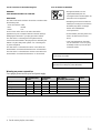
1) Use the correct plug for your country.
Voor de klanten in Nederland
• Dit apparaat bevat een vast
ingebouwde batterij die niet
vervangen hoeft te worden tijdens de
levensduur van het apparaat.
• Raadpleeg uw leverancier indien de
batterij toch vervangen moet worden.
De batterij mag alleen vervangen
worden door vakbekwaam
servicepersoneel.
• Gooi de batterij miet weg maar lever
deze in als klein chemisch afval
(KCA).
• Lever het apparaat aan het einde
van de levensduur in voor recycling,
de batterij zal dan op correcte wijze
verwerket worden.
The socket-outlet should be installed near the equipment
and be easily accessible.
Apparaten ma kun tilkoples jordet stikkontakt.
Apparatet må kun tilkoples jordet stikkontakt.
Warning on power connection
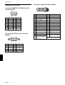
Use a proper power cord for your local power supply.
The United States, Continental UK, Ireland, Japan
Canada Europe Australia, New Zealand
Plug type VM0233 290B YP-12A COX-07 —
1)
YP332
Female end VM0089 386A YC-13B COX-02 VM0310B YC-13
Cord type SJT SJT H05VV-F H05VV-F N13237/CO-228 VCTF
Rated Voltage & Current 10A/125V 10A/125V 10A/250V 10A/250V 10A/250V 7A/125V
Safety approval UL/CSA UL/CSA VDE VDE VDE DENAN
Cord length (max.) 4.5m (177 1/4 inches) —

4 (GB)

5 (GB)
English
GB
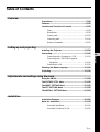
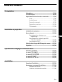
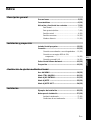
Table of Contents
Overview
Precautions ............................................................... 7 (GB)
Features..................................................................... 8 (GB)
Location and Function of Controls......................... 9 (GB)
Front......................................................................... 9 (GB)
Rear/Bottom............................................................. 9 (GB)
Control panel.......................................................... 10 (GB)
Connector panel ..................................................... 12 (GB)
Remote Commander .............................................. 13 (GB)
Setting up and projecting
Installing the Projector........................................... 14 (GB)
Connecting.............................................................. 15 (GB)
Connecting with a Computer or a VCR................. 15 (GB)
Connecting with a 15k RGB/Component
Equipment......................................................... 16 (GB)
Connecting to LAN................................................ 16 (GB)
Selecting the Menu Language............................... 18 (GB)
Projecting ................................................................ 18 (GB)
Adjustments and settings using the menu
Using the MENU...................................................... 21 (GB)
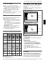
The PICTURE CTRL Menu ..................................... 22 (GB)
The INPUT SETTING Menu .................................... 23 (GB)
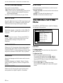
The SET SETTING Menu ........................................ 25 (GB)
The INSTALL SETTING Menu ................................ 26 (GB)
Installation
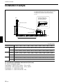
Installation Example............................................... 28 (GB)
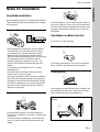
Notes for Installation.............................................. 29 (GB)
Unsuitable Installation ........................................... 29 (GB)
Unsuitable Conditions for Use............................... 29 (GB)

6 (GB)
Maintenance
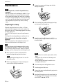
Maintenance............................................................ 30 (GB)
Replacing the Lamp ............................................... 30 (GB)
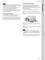
Cleaning the Air Filter ........................................... 31 (GB)
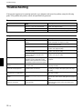
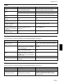
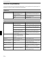
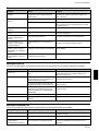
Troubleshooting ..................................................... 32 (GB)
Other
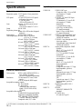
Specifications ......................................................... 34 (GB)
Index ........................................................................ 37 (GB)

7 (GB)
Precautions
On safety
•Check that the operating voltage of your unit is
identical with the voltage of your local power
supply.
•Should any liquid or solid object fall into the cabinet,
unplug the unit and have it checked by qualified
personnel before operating it further.
•Unplug the unit from the wall outlet if it is not to be
used for several days.
•To disconnect the cord, pull it out by the plug. Never
pull the cord itself.
•The wall outlet should be near the unit and easily
accessible.
•The unit is not disconnected to the AC power source
(mains) as long as it is connected to the wall outlet,
even if the unit itself has been turned off.
•Do not look into the lens while the lamp is on.
•Do not aim the laser at people or not look into the
laser transmitter.
•Do not place your hand or objects near the
ventilation holes — the air coming out is hot.
•Be careful not to catch your fingers by the adjuster
when you lift up the projector. Do not push hard on
the top of the projector with the adjuster out.
•Be sure to grasp the both sides of the projector with
both your hands when carrying the projector.
On illumination
•To obtain the best picture, the front of the screen
should not be exposed to direct lighting or sunlight.
•Ceiling-mounted spot lighting is recommended. Use
a cover over fluorescent lamps to avoid lowering the
contrast ratio.
•Cover any windows that face the screen with opaque
draperies.
•It is desirable to install the projector in a room where
floor and walls are not of light-reflecting material. If
the floor and walls are of reflecting material, it is
recommended that the carpet and wall paper be
changed to a dark color.
On preventing internal heat build-up
After you turn off the power with the I /
1
key on the
Remote Commander or on the control panel, do not
disconnect the unit from the wall outlet while the
cooling fan is still running.
Caution
The projector is equipped with ventilation holes
(intake) on the bottom and ventilation holes (exhaust)
on the front. Do not block or place anything near these
holes, or internal heat build-up may occur, causing
picture degradation or damage to the projector.
On cleaning
•To keep the cabinet looking new, periodically clean
it with a soft cloth. Stubborn stains may be removed
with a cloth lightly dampened with a mild detergent
solution. Never use strong solvents, such as thinner,
benzene, or abrasive cleansers, since these will
damage the cabinet.
•Avoid touching the lens. To remove dust on the lens,
use a soft dry cloth. Do not use a damp cloth,
detergent solution, or thinner.
•When replacing the lamp, clean the filter.
On repacking
Save the original shipping carton and packing
material; they will come in handy if you ever have to
ship your unit. For maximum protection, repack your
unit as it was originally packed at the factory.
On LCD projector
The LCD projector is manufactured using high-
precision technology. You may, however, see tiny
black points and/or bright points (red, blue, or green)
that continuously appear on the LCD projector. This is
a normal result of the manufacturing process and does
not indicate a malfunction.
Precautions
Overview

8 (GB)
Features
High brightness, high picture quality
•High brightness
The high aperture ratio LCD panel with a microlens
and the 300 W UHP lamp provide high brightness
(light output 5200 ANSI lumen) and excellent
uniformity on the picture.
•High contrast
The newly developed optical system enables
projection of twice as high a contrast as that of Sony’s
current models.
•High resolution
By adopting three 1.3-inch, approximately 790,000-
pixels XGA panels, this projector can project sharp
picture with the resolutions of 1024 × 768 pixels for
RGB input, and 750 horizontal TV lines for video
input.
•High picture performance
The DDE (Dynamic Detail Enhancer) technology,
originally developed by Sony, enables converting
interlace format video signals to progressive format,
allowing you to obtain a detailed picture.
The technology also reproduces the film sources in 2-
3 Pull-Down format with smooth picture movement.
The internal RGB enhancer provides sharper RGB
pictures. The 10-bit 3D Digital Gamma correction for
good picture uniformity is also provided.
Convenient and flexible setup
•Power zoom/power focus lens and the lens shift
function
The projector is equipped with a 1.3-times power
zoom and power focus lens, which allows you to
change the size of the projected image without having
to move the projector. The lens shift function enables
you to install the projector in a wide range of
locations, without worrying about trapezoid
distortion. Also, three optional lenses are available for
the projector, depending on your setup condition.
•Center positioned lens
The projector is designed to locate the lens in the
center of the unit. This enables an easy setup, as the
lens center aligns with the center of the screen.
•Tilt installation (in front and rear)
You can install the projector by tilting it 90 degrees at
the rear or 90 degrees in front. You can use a mirror
for rear projection.
•Twin stack installation
Thanks to the lens shift function, two projectors can
be stacked, which improves the brightness of the
image.
Multi scan compatibility
•DVI and 5BNC connectors
The projector has the DVI (Digital Visual Interface)
connector, the up-to-date digital input connector,
which allows you to connect to the digital or analog
RGB equipment equipped with the DVI output. The
5BNC input connectors allow you to connect to
workstation output high-resolution signals and to
connect to a computer from a long distance.
The projector has 44 preset data for input signals in
the memory, which allows you to project a clear
picture on the screen simply by connecting equipment
and pressing the APA (Auto Pixel Alignment) key.
•Accept various input signals
The projector accepts video signals of the composite,
S video and component, and can also display the 15k
RGB, DTV, HDTV, VGA
1)
, SVGA
1)
, XGA
1)
, SXGA
1)
and UXGA
1)
(fV=60 Hz) signals.
•Scan converter built-in
The projector has a built-in scan converter which
converts the input signal within 1024 × 768 pixels.
•Compatible with six color systems
NTSC
3.58, PAL, SECAM, NTSC 4.43
2)
, PAL-M or
PAL-N color system can be selected automatically or
manually.
Other function
•Networking compatibility
The projector is equipped with a PC CARD slot and
ETHER connector, which allows you to connect to a
wired or wireless LAN.
For information on the networking function of this
projector, refer to the supplied Operating Instructions for
Networking.
Features
.........................................................................................................................................................................................................
1) VGA, SVGA, XGA, SXGA and UXGA are registered trademarks of the International Business Machines Corporation,
U.S.A.
2) NTSC4.43 is the color system used when playing back a video recorded on NTSC on an NTSC4.43 system VCR.

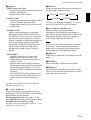
9 (GB)
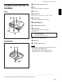
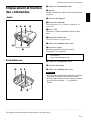
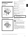
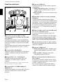
Location and Function of
Controls
Front
1 Front remote control detector
2 Lens
Remove the lens cap before projection.
3 Lens cover
4 Control panel
For details, see “Control panel” on page 10 (GB).
5 AC IN socket
Connects the supplied AC power cord.
6 Connector panel
For details, see page 12 (GB).
7 Ventilation holes (exhaust)
8 Security lock
Connects to an optional security cable
(Kensington’s
1)
).
Home page address:
http://www.kensington.com/
9 Rear remote control detector
q; Lamp cover
qa Ventilation holes (intake)
Notes
•Do not place anything near the ventilation holes as it
may cause internal heat build-up.
•Do not place your hand or objects near the
ventilation holes — the air coming out is hot.
Rear/Bottom
Location and Function of Controls
12 3 4
56
7
8
9q;qa
qsqd
.........................................................................................................................................................................................................
1) Kensington is a registered trademark of Kensington Technology Group.

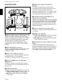
10 (GB)
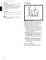
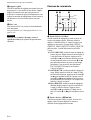
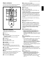
Control panel
1 LENS CONTROL key
Enters the focus, zoom or shift adjustment mode. Next
adjust them using the arrow keys. Each time you press
the key, the mode changes to LENS FOCUS, LENS
ZOOM and LENS SHIFT in order. The mode
currently selected is displayed on the screen.
LENS FOCUS: Enters the focus adjustment mode.
Next adjust the focus using the arrow keys. Press
the M or , key to focus on a picture further
back, and the m or < key to focus on a forward
picture. You cannot select LENS FOCUS when
you attach the optional lens.
LENS ZOOM: Enters the zoom adjustment mode.
Next adjust the picture size using the arrow keys.
Press the M or , key to enlarge the picture size,
and the m or < key to reduce it. You cannot
select LENS ZOOM when you attach the optional
lens.
LENS SHIFT: Enters the shift adjustment mode.
Next adjust the vertical position of the picture
using the arrow keys. Press the M or , key to
move the picture upward, and the m or < key to
move it downward.
2 Arrow keys (M/m/</,)
Used to adjust focus, zoom and shift, or to move the
cursor or make various adjustments in the menu.
qs Adjuster
Use the adjusters to keep the projector level if it is
installed on an uneven surface.
Adjust the height so that the projector becomes level.
The projector is raised by turning the adjusters
clockwise, or it is lowered by turning them
counterclockwise.
qd Air filter
To remove the air filter, pull it out horizontally with
this part.
For details, see “Cleaning the Air Filter” on page 31 (GB).
Note
When replacing the lamp, also clean the filter to
ensure optimal performance.
Location and Function of Controls
RESET
LENS CONTROL
POWER SAVING ON/STANDBY
MENU
TEMP/FAN
ENTER
APA
LAMP/COVER
INPUT
12 3
456789

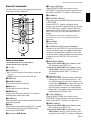
11 (GB)
5 INPUT key
Selects the input signal. Each time you press the key,
the input signal switches as follows:
INPUT C is not displayed when INPUT C FUNC. is
set to OFF in the INSTALL SETTING menu.
6 APA (Auto Pixel Alignment) key
Adjusts a picture to be projected clearest
automatically while a signal from the computer is
input. Adjusts the shift (up/down and left/right) at the
same time automatically. (Only when inputting a
RGB (analog) signal from the computer).
Note
Press the APA key when the full image is displayed
on the screen. If there are black edges around the
image, the APA function will not function properly
and the image may extend beyond the screen.
7 MENU key
Displays the on-screen menu. Press again to clear the
menu.
8 ENTER key
Enters the settings of items in the menu system.
9 RESET key
Resets the value of an item back to its factory preset
value. This key functions when the menu or a setting
item is displayed on the screen.
Location and Function of Controls
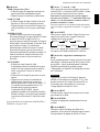
3 Indicators
TEMP (Temperature)/FAN
• Lights up when temperature inside the projector
becomes unusually high.
• Flashes when the fan is broken.
LAMP/COVER
• Lights up when the lamp has reached the end of
its life or becomes a high temperature.
• Flashes when the lamp cover or air filter is not
secured firmly.
POWER SAVING
Lights up when the projector is in the power
saving mode. When POWER SAVING in the
SET SETTING menu is set to ON, the projector
goes into the power saving mode if no signal is
input for 10 minutes. Although the lamp goes out,
the cooling fan keeps running. In the power
saving mode, any key does not function for the
first 40 seconds. The power saving mode is
canceled when a signal is input or any key is
pressed.
ON/STANDBY
• Lights in red when the AC power cord is
plugged into the wall outlet. Once in the
standby mode, you can turn on the projector
with the
I / 1
key.
• Lights in green when the power is turned on.
• Flashes in green while the cooling fan runs after
turning off the power with the
I / 1
key. The
fan runs for about 120 seconds after turning off
the power.
The ON/STANDBY indicator flashes quickly
for the first 40 seconds. During this time, you
cannot turn the power back on with the
I / 1
key.
For details on the LAMP/COVER and the TEMP/FAN
indicators, see page 33 (GB).
4
I
/
1
(
on / standby
)
key
Turns on the projector when the projector is in the
standby mode. The ON/STANDBY indicator lights in
green when the power is turned on.
When turning off the power, press the I /
1
key
twice following the message on the screen, or press
and hold the key for about one second.
For details on steps for turning off the power, see “To turn
off the power” on page 20 (GB).
B INPUT-A B INPUT-B B INPUT-C
S-VIDEO b VIDEO b

12 (GB)
Location and Function of Controls
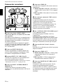
6 TRIG (trigger output) jack (monaural
minijack)
The signal is transmitted from this jack to the
connected equipment whether the projector is on or
off. (This is not a power source for external
equipment.) Approximately 12 V DC signal is output
when the projector power is on. The signal is 0 volt
level output when the projector power is off.
7 CONTROL S/PLUG IN POWER (DC 5V
output) jack (stereo minijack)
Connects to the control S out jacks of the Sony equipment.
Connects to the CONTROL S OUT jack on the supplied
Remote Commander when using it as a wired Remote
Commander. In this case, you do not need to install the
batteries in the Remote Commander, since the power is
supplied from this jack.
8 RS-232C connector (D-sub 9-pin, female)
Connects to a computer to operate the projector from
the computer.
9 VIDEO OUT connectors
S VIDEO (mini DIN 4-pin): Used as loop-through
output via the S VIDEO IN connector.
VIDEO (BNC type): Used as loop-through output
via the VIDEO IN connector.
q; MONITOR OUT connector (HD D-sub 15-pin,
female)
Connects to the monitor input connector on the
monitor. Outputs signals from the selected channel in
the INPUT A (5BNC) or INPUT B (DVI) connector.
This connector does not output any signals from the
DVI connector if the input signal is digital.
Connector panel
1 INPUT A 5BNC connectors (R/R-Y/PR, G/Y, B/
B-Y/P
B, SYNC/HD, VD connectors) (BNC type)
Connect to a high-resolution computer or VCR where
signals are transmitted long distances; for example,
when the projector is installed on the ceiling.
According to the connected equipment, computer,
component (R-Y/Y/B-Y), HDTV or DTV signal is
selected.
2 INPUT B RGB (DVI) connector
Connect to equipment equipped with the DVI output
(digital or analog RGB) using a commercially
available DVI cable.
3 INPUT C PC CARD slot (Type II)
A wireless LAN PC card or PC memory card can be
attached according to your requirement.
For details, see “Installing a PC card” on page 16 (GB).
4 INPUT C ETHER connector (10BASE-T/
100BASE-TX)
Connect to a computer on the same LAN with the
LAN cable when you use the networking function of
this projector.
5 VIDEO IN connectors
Connect to external video equipment such as a VCR.
S VIDEO (mini DIN 4-pin):
Connects to the S video
output (Y/C video output) on video equipment.
VIDEO (BNC type): Connects to the composite
video output.
Front
INPUT A
R/R-Y/P
R
INPUT B
RGB (DVI)
INPUT C
ETHER
B/B-Y/P
BG/Y SYNC/HD
MONITOR OUT
VIDEO IN
VIDEO OUT
S VIDEO VIDEO
TRIG
RS-232C
PLUG IN POWER
CONTROL S
VD
4567
89
0
1
32

13 (GB)
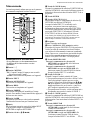
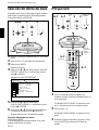
Remote Commander
The keys which have the same names as those on the
control panel function identically.
Notes on laser beam
• Do not look into the laser transmitter.
• Do not aim the laser at people.
1
I
/
1
key
2 MUTING key
PIC: Cuts off the picture. Press again to restore the
picture.
AUDIO: This key does not work in the unit.
3 INPUT key
4 D KEYSTONE key
This key does not work in the unit.
5 HELP key
This key does not work in the unit.
6 FREEZE key
Used to freeze the picture projected. To cancel the
freezed picture, press the key again.
7 LASER key
Emits laser beam from the laser transmitter while you
keep this key pressed.
8 Mouse
This functions as the mouse in the INPUT C window
of this projector when the PJ/NETWORK select
switch is set to NETWORK.
9 Arrow keys (M/m/</,)
Location and Function of Controls
0 R (right) CLICK key
When the PJ/NETWORK select switch is set to
NETWORK, this key functions as the right button on
the mouse in the INPUT C window of this projector.
qa ENTER key
qs FUNCTION 1/2/3 keys
Functions when the PJ/NETWORK select switch is set
to NETWORK.
When the INPUT C window is displayed on the
projector, you can start an application by just pressing
a FUNCTION key. To use this function, allocate an
application to a FUNCTION key. Allocation to the
FUNCTION 3 key is set to the keyboard software
display.
For details on how to allocate an application to the
FUNCTION keys, refer to the Operating Instructions for
Networking.
qd Strap holder
Attaches a strap.
qf CONTROL S OUT jack (stereo minijack)
Connects to the CONTROL S IN jack on the projector
with the connecting cable (not supplied) when using
the Remote Commander as a wired one. In this case,
you do not need to install the batteries since the power
is supplied via the CONTROL S IN jack on the
projector.
qg RESET/ESCAPE key
When the PJ/NETWORK select switch is set to
PJ: Functions as the RESET key.
When the PJ/NETWORK select switch is set to
NETWORK: Functions as the ESCAPE key of
the keyboard when the INPUT C window is
displayed.
qh D ZOOM +/– key
Enlarges the image at a desired location on the screen.
+: Pressing the + key once displays the icon. This
icon indicates the point you want to enlarge. Use
an arrow key (M/m/</,) to move the icon to the
point to be enlarged. Press the + key repeatedly
until the image is enlarged to your requirements.
–: Pressing the – key reduces an image that has been
enlarged with the D ZOOM + key.
qj L (left) CLICK key
When the PJ/NETWORK select switch is set to
NETWORK, this key functions as the left button on a
mouse in the INPUT C window of the projector.
qk MENU/TAB key
When the PJ/NETWORK select switch is set to
PJ: Functions as the MENU key.
When the PJ/NETWORK select switch is set to
NETWORK: Functions as the TAB key of the
keyboard when the INPUT C window is displayed.
MUTING
PIC
AUDIO
LENS
APA
LASER
INPUT
D KEYSTONE
HELP
PJ NETWORK
ON
COMMAND
OFF
VOLUME
ENTER
FUNCTION
RM-PJM15
PROJECTOR
D ZOOM
CLICK
RESET/
ESCAPE
MENU/
TAB
R
1
2
3
1
2
3
4
8
9
q;
qa
qs
wg
wf
wd
ws
wa
w;
ql
qk
qj
qh
qg
qd,qf
wh
FREEZE
6
7
5

14 (GB)
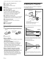
Location and Function of Controls / Installing the Projector
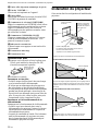
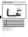
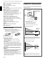
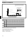
Installing the Projector
This section describes the installation arrangements
for installing the projector.
Horizontal center
of the screen
Projection distance
The distance between the lens and the screen
varies depending on the screen size.
Refer to the chart on page 28 (GB).
Be sure to install
the battery from
the # side.
Install the projector so
that the tip of the lens
is within this area.
Installation
area
Vertical
center of
the screen
Adjust the horizontal positioning of the projector so that the
center of the lens is aligned with the horizontal center of the
screen.
Adjust the vertical and horizontal positioning of the projector.
Vertical positioning (side view)
Screen
Adjustable
shift range
You can adjust the angle of projection by performing the shift
adjustment (page 19 (GB)). Install the projector so that the
center of the lens is between the bottom edge of the screen
and the center of the screen.
Horizontal positioning (top view)
Screen
Center of the projector
ql APA (Auto Pixel Alignment) key
w; VOLUME +/− keys
This key does not work in the unit.
wa LENS key
This has the same function as the LENS CONTROL
key on the control panel.
ws PJ/NETWORK select switch
To use the Remote Commander for network
operations, set the switch to NETWORK. Set the
switch to PJ to use the Remote Commander for
normal operations other than networking.
wd COMMAND ON/OFF switch
When this switch is set to OFF, no key on the Remote
Commander function. This saves the battery power.
wf Transmission indicator
Lights up when you press a key on the Remote
Commander.
wg Infrared transmitter
wh Laser transmitter
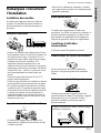
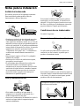
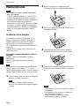
Battery installation
1 Push and slide to open the lid, then install the two
size AA (R6) batteries (supplied) with the correct
polarity.
2 Replace the lid.
Notes on batteries
•Make sure that the battery orientation is correct when
inserting batteries.
•Do not mix an old battery with a new one, or
different types of batteries.
•If you will not use the Remote Commander for a
long time, remove the batteries to avoid damage
from battery leakage. If batteries have leaked,
remove them, wipe the battery compartment dry and
replace the batteries with new ones.
Notes on Remote Commander operation
•Make sure that there is nothing to obstruct the
infrared beam between the Remote Commander and
the remote control detector on the projector.
•The operation range is limited. The shorter the
distance between the Remote Commander and the
projector is, the wider the angle within which the
commander can control the projector.

15 (GB)
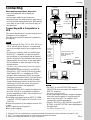
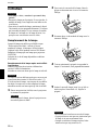
Connecting
When making connections, be sure to:
•turn off all equipment before making any
connections.
•use the proper cables for each connection.
•insert the plugs of the cables properly; plugs that are
not fully inserted often generate noise. When pulling
out a cable, be sure to pull it out from the plug, not
the cable itself.
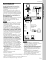
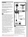
Connecting with a Computer or a
VCR
This section describes how to connect the projector to
a computer or video equipment.
Also refer to the instruction manual of equipment to
be connected.
Notes
•This unit accepts the VGA, SVGA, XGA, SXGA or
UXGA (60 Hz) signals. However, we recommend
you to set the output signal of your computer to the
XGA.
•If you set your computer, such as a notebook type
IBM PC/AT
1)
compatible, to output the signal to
both the display of your computer and the external
monitor, the picture of the external monitor may not
appear properly. In such cases, set the output mode
of your computer to output the signal to only the
external monitor.
For details, refer to the operating instructions supplied
with your computer.
•This projector complies with DDC1 and DDC2B
(Plug & Play). (DDC1 and DDC2B are the Display
Data Channel (DDC
TM
)
2)
standard in the VESA
standard.) When connecting a DDC1 host system,
the projector synchronizes with V.CLK that follows
the VESA standard and outputs EDID (Extended
Display Identification Data) to the data line. When
connecting a DDC2B host system, the projector
automatically switches to the appropriate
communication mode.
The INPUT B RGB (DVI) connector complies with
the VESA DDC2B. If your computer or graphics
board is compatible with DDC, turn on the power of
the equipment as follows:
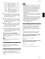
1 According to the input signal, set INPUT-B TERM.
in the SET SETTING menu to PC ANALOG or PC
DIGITAL.
2 Connect the projector to the computer with the DVI
cable.
3 Turn on the power of the projector.
4 Boot up the computer.
Connecting
.........................................................................................................................................................................................................
1) IBM and PC/AT are a trademark and a registered trademark of International Business Machines Corporation, U.S.A.
2) DDC
TM
is a registered trademark of the Video Electronics Standard Association.
3) Macintosh is a registered trademark of Apple Computer Inc.
Setting up and projecting
INPUT A
R/R-Y/P
R
INPUT B
RGB (DVI)
INPUT C
ETHER
B/B-Y/P
B
G/Y SYNC/HD
MONITOR OUT
VIDEO IN
VIDEO OUT
S VIDEO VIDEO
TRIG
RS-232C
PLUG IN POWER
CONTROL S
VD
Computer
to DVI
output
DVI cable
(not supplied)
VCR
to S video
output
S-Video cable
(not supplied)
to video
output
Video
cable (not
supplied)
Front of the projector
SMF-400
Monitor
cable
(5BNC
y HD D-
sub 15-
pin) (not
supplied)
to monitor
out
SMF-410 Monitor cable
(HD D-sub 15-pin y HD
D-sub 15-pin) (not
supplied)
Monitor
Computer
Notes
• Set INPUT-A in the SET SETTING menu to
COMPUTER when you connect the computer to the
INPUT A connector.
For details, see page 26 (GB).
• When connecting a Macintosh
3)
computer equipped
with video output connector of a type having two
rows of pins to the INPUT A connector, use a
commercially available plug adaptor.
• Select PC DIGITAL or PC ANALOG using INPUT-
B TERM. in the SET SETTING menu depending on
the signal input.
For details, see page 26 (GB).
to monitor input

16 (GB)
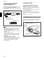
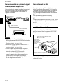
Connecting to LAN
This projector is compatible with networking.
Installing a wireless LAN PC card or using the
ETHER connector enables you to connect the
projector to a wireless or wired LAN. You can also
install a PC memory card.
This section describes how to connect to LAN and
how to install a PC card.
Whenever you connect the projector to LAN, set
INPUT C FUNC. in the INSTALL SETTING menu
to ON.
For details, see page 27 (GB).
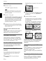
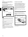
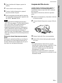
Installing a PC card
When you use a wireless LAN PC card or memory
card, insert the card into the INPUT C PC CARD
slot.
To remove the PC card from the slot, press the eject
button.
INPUT A
R/R-Y/P
R
INPUT B
RGB (DVI)
INPUT C
ETHER
B/B-Y/P
B
G/Y SYNC/HD
MONITOR OUT
VIDEO IN
VIDEO OUT
S VIDEO VIDEO
TRIG
RS-232C
PLUG IN POWER
CONTROL S
VD
Connecting with a 15k RGB/
Component Equipment
This section describes how to connect the projector
with a 15k RGB/component equipment.
Also refer to the instruction manuals of the equipment
to be connected.
Connecting
Notes
• Set the aspect ratio using ASPECT in the INPUT
SETTING menu according to the input signal.
For details, see page 24 (GB).
•Select the input signal using INPUT-A in the SET
SETTING menu.
For details, see page 26 (GB).
•Use the composite sync signal when you input the
external sync signal from 15k RGB/component
equipment.
Connecting to a HDTV 1035/60i
Since the screen ratio of a high definition image is
16:9 and 576 lines are displayed in the vertical
direction, the image displayed is not a high-
definition image.
Front of the projector
to RGB/component
output
15k RGB/component equipment
Open the lid of the slot, then insert the PC card
to the INPUT C PC CARD slot
PC card
Insert the card
with the arrow
mark facing
toward the slot.
The eject button pops out
when inserting.
Monitor cable
(not supplied)

17 (GB)
PC CARD
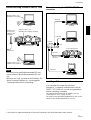
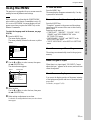
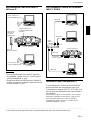
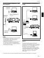
Connection using the INPUT C ETHER
connector
Installing a PC memory card
If you store the file created with Microsoft
PowerPoint
1)
in a memory card and insert it into the
INPUT C PC CARD slot, you can run a presentation
without connecting a computer.
For attaching and removing the PC memory card, see
“Installing a PC card” on page 16 (GB).
For details on the specified/recommended PC card, see the
attached “Specified/recommended PC card list.”
Connection using a wireless LAN PC card
Notes
•For details on the specified/recommended PC card,
see the attached “Specified/recommended PC card
list.”
•When you use LAN, you must set the IP address. For
details of setting IP address, etc., see the supplied
“Operating Instructions for Networking.”
PC CARD
Connecting
Front of the projector
Wireless LAN PC card
(IEEE802.11b compliant)
Computer
Wireless LAN
access point
(IEEE802.11b
compliant)
Wireless LAN PC card
(IEEE802.11b compliant) (specified)
to Hub/router
Wireless LAN PC card
(IEEE802.11b compliant)
Computer
Computer
Front of the projector
INPUT C ETHER
connector
to router
LAN cable
Hub
Computer
Computer
.........................................................................................................................................................................................................
1) PowerPoint is a registered trademark of Microsoft Corporation in the United States and/or other countries.
LAN cable
LAN cable
LAN cable

18 (GB)
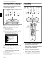
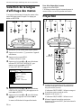
Projecting
1 After all equipment is connected completely, plug
the AC power cord into the wall outlet.
The ON/STANDBY indicator lights in red and the
projector goes into the standby mode.
2 Press the I /
1
key to turn on the projector.
The ON/STANDBY indicator lights in green.
3 Turn on equipment connected to the projector.
Press the INPUT key to select the input source.
2
4~7
32
4~7
MUTING
PIC
AUDIO
LENS
APA
LASER
INPUT
D KEYSTONE
HELP
PJ NETWORK
ON
COMMAND
OFF
VOLUME
ENTER
FUNCTION
RM-PJM15
PROJECTOR
D ZOOM
CLICK
RESET/
ESCAPE
MENU/
TAB
R
1
2
3
FREEZE
4~7
3
4~7
RESET
LENS CONTROL
POWER SAVING ON/STANDBY
MENU
TEMP/FAN
ENTER
APA
LAMP/COVER
INPUT
Rear remote
control detector
ON/STANDBY
indicator
APA key
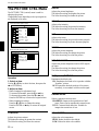
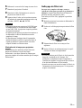
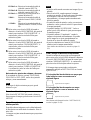
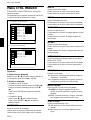
Selecting the Menu Language/Projecting
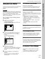
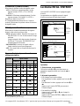
Selecting the Menu Language
You can select the language for displaying in the
menu and other on screen displays from 9 languages.
The factory setting is ENGLISH.
1 Plug the AC power cord into the wall outlet.
2 Press the I /
1
key to turn on the power.
3 Press the MENU key.
The menu display appears.
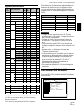
4 Press the M or m key to select the SET SETTING
menu, then press the , or ENTER key.
The SET SETTING menu appears.
5 Press the M or m key to select LANGUAGE, then
press the , or ENTER key.
6 Press the M or m key to select a language, then
press the < or ENTER key.
The menu changes to the selected language .
To clear the menu display
Press the MENU key.
The menu display disappears automatically if no key
is pressed for one minute.
APA key
RESET
LENS CONTROL
POWER SAVING ON/STANDBY
MENU
TEMP/FAN
ENTER
APA
LAMP/COVER
INPUT
1
4,5,6 3 2
SET SETTING
STATUS: ON
INPUT-B TERM.
: PC DIGITAL
INPUT-A: COMPUTER
AUTO INPUT SEL
: OFF
LANGUAGE
: ENGLISH
POWER SAVING
: OFF
IR RECEIVER
: FRONT&REAR
INPUT-A

19 (GB)
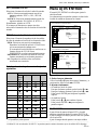
Projecting
INPUT-A:Selects video signal input from the
INPUT A connector.
INPUT-B: Selects video signal input from the
INPUT B connector.
INPUT-C: Selects to display the Windows CE
window.
VIDEO: Selects video signal input from the
VIDEO (VIDEO IN) jack.
S-VIDEO:Selects video signal input from the S
VIDEO (VIDEO IN) jack.
4 Press the LNES key on the Remote Commander
or LENS CONTROL key on the control panel
repeatedly to display “LENS FOCUS.” Then
press the arrow keys to adjust.
5 Press the LNES key on the Remote Commander
or LENS CONTROL key on the control panel
repeatedly to display “LENS ZOOM.” Then press
the arrow keys to adjust.
6 Press the LNES key on the Remote Commander
or LENS CONTROL key on the control panel
repeatedly to display “LENS FOCUS.” Then
press the arrow keys to adjust again.
7 Press the LNES key on the Remote Commander
or LENS CONTROL key on the control panel
repeatedly to display “LENS SHIFT.” Then press
the arrow keys to adjust.
Note on focus and zoom adjustments
If the optional VPLL-ZM101, VPLL-ZM31 or VPLL-
FM21 lens is installed, perform the focus and zoom
adjustments manually.
Note
Looking into the lens when projecting may cause
injury to your eyes.
Cut off the picture
Press the PIC MUTING key on the Remote
Commander. To restore the picture, press the PIC
MUTING key again.
To get the clearest picture
You can get the suitable picture when a signal from
the computer is input. Press the APA key.
The picture is automatically adjusted to be projected
clearest.
Notes
•Adjust the signal when the still picture is displayed
on the screen.
•Press the APA key when the full image is displayed
on the screen. If there are black edges around the
image, the APA function will not function properly
and the image may extend beyond the screen.
•If you switch the input signal or re-connect a
computer, press the APA key again to get the
suitable picture.
•“ADJUSTING” appears on the screen. To restore the
original screen, press the APA key again during the
adjustment.
•“Complete!” appears on the screen when the picture
is adjusted properly. The picture may not be adjusted
properly depending on the kinds of input signals.
•Adjust the items in the INPUT SETTING menu
when you adjust the picture manually.
For details, see page 23 (GB).
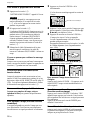
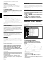
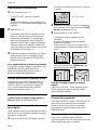
To correct the trapezoid
When the projecting image is a trapezoid, press the
LNES key on the Remote Commander or LENS
CONTROL key on the control panel repeatedly to
display “LENS SHIFT.” Then press the arrow keys to
adjust.
If the image is still a trapezoid, correct it in DIGIT
KEYSTONE in the INSTALL SETTING menu.
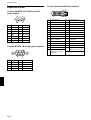
When the base edge is longer than the upper
edge as shown in the figure below:
When the upper edge is longer than the base
edge as shown in the figure below:
For details on “DIGIT KEYSTONE,” see page 27 (GB).
Set the value to negative.
Set the value to positive.

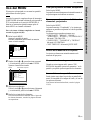
20 (GB)
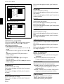
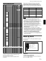
The Digital Zoom icon appears in the center of the
image.
2 Move the icon to the point on the image you want
to enlarge. Use the arrow keys (M/m/</,) to
move the icon.
3 Press the D ZOOM + key again.
The image where the icon is located is enlarged.
The enlargement ratio is displayed on the screen
for a few seconds.
By pressing the + key repeatedly, the image size
increases. (ratio of enlargement: max. 4 times)
Use the arrow keys (M/m/</,) to scroll the
enlarged image.
To return the image back to its original size
Press the D ZOOM – key. Just pressing the RESET
key returns the image back to its original size
immediately.
To freeze the image projected (Freeze
function)
Press the FREEZE key. “FREEZE” appears when the
key is pressed. This function works only when a
signal from a computer is input.
To restore the original screen, press the FREEZE key
again.
To use the Laser Pointer function
Press the LASER key on the Remote Commander.
The laser pointer appears. The pointer is helpful in
indicating a particular point on the screen.
Projecting
Digital Zoom icon
To turn off the power
1 Press the I /
1
key.
“Power OFF?” appears on the screen.
Note
The message will disappear if you press any key
except the I /
1
key, or if you do not press any
key for five seconds.
2 Press the I /
1
key again.
The ON/STANDBY indicator flashes in green and
the fan continues to run for about 120 seconds to
reduce the internal heat. Also, the ON/STANDBY
indicator flashes quickly for the first 40 seconds.
During this time, you will not be able to turn the
power back on with the I /
1
key.
3 Unplug the AC power cord from the wall outlet
after the fan stops running and the ON/STANDBY
indicator lights in red.
When you cannot confirm the on-screen
message
When you cannot confirm the on-screen message in a
certain condition, you can turn off the power by
holding the I /
1
key for about one second.
Direct power on/off function
When the projector is turned on or off by using a
system switch such as a breaker, set DIRECT PWR
ON to ON (page 27 (GB)). You can also disconnect
the power cord not pressing the I /
1
key.
About the air filter cleaning
When replacing the lamp, also clean the filter to
ensure optimal performance.
To enlarge the image (Digital Zoom
function)
You can enlage the point on the image you select.
This function works only when a signal from a
computer is input.
1 Press the D ZOOM + key on the Remote
Commander.
La page est en cours de chargement...
La page est en cours de chargement...
La page est en cours de chargement...
La page est en cours de chargement...
La page est en cours de chargement...
La page est en cours de chargement...
La page est en cours de chargement...
La page est en cours de chargement...
La page est en cours de chargement...
La page est en cours de chargement...
La page est en cours de chargement...
La page est en cours de chargement...
La page est en cours de chargement...
La page est en cours de chargement...
La page est en cours de chargement...
La page est en cours de chargement...
La page est en cours de chargement...
La page est en cours de chargement...
La page est en cours de chargement...
La page est en cours de chargement...
La page est en cours de chargement...
La page est en cours de chargement...
La page est en cours de chargement...
La page est en cours de chargement...
La page est en cours de chargement...
La page est en cours de chargement...
La page est en cours de chargement...
La page est en cours de chargement...
La page est en cours de chargement...
La page est en cours de chargement...
La page est en cours de chargement...
La page est en cours de chargement...
La page est en cours de chargement...
La page est en cours de chargement...
La page est en cours de chargement...
La page est en cours de chargement...
La page est en cours de chargement...
La page est en cours de chargement...
La page est en cours de chargement...
La page est en cours de chargement...
La page est en cours de chargement...
La page est en cours de chargement...
La page est en cours de chargement...
La page est en cours de chargement...
La page est en cours de chargement...
La page est en cours de chargement...
La page est en cours de chargement...
La page est en cours de chargement...
La page est en cours de chargement...
La page est en cours de chargement...
La page est en cours de chargement...
La page est en cours de chargement...
La page est en cours de chargement...
La page est en cours de chargement...
La page est en cours de chargement...
La page est en cours de chargement...
La page est en cours de chargement...
La page est en cours de chargement...
La page est en cours de chargement...
La page est en cours de chargement...
La page est en cours de chargement...
La page est en cours de chargement...
La page est en cours de chargement...
La page est en cours de chargement...
La page est en cours de chargement...
La page est en cours de chargement...
La page est en cours de chargement...
La page est en cours de chargement...
La page est en cours de chargement...
La page est en cours de chargement...
La page est en cours de chargement...
La page est en cours de chargement...
La page est en cours de chargement...
La page est en cours de chargement...
La page est en cours de chargement...
La page est en cours de chargement...
La page est en cours de chargement...
La page est en cours de chargement...
La page est en cours de chargement...
La page est en cours de chargement...
La page est en cours de chargement...
La page est en cours de chargement...
La page est en cours de chargement...
La page est en cours de chargement...
La page est en cours de chargement...
La page est en cours de chargement...
La page est en cours de chargement...
La page est en cours de chargement...
-
 1
1
-
 2
2
-
 3
3
-
 4
4
-
 5
5
-
 6
6
-
 7
7
-
 8
8
-
 9
9
-
 10
10
-
 11
11
-
 12
12
-
 13
13
-
 14
14
-
 15
15
-
 16
16
-
 17
17
-
 18
18
-
 19
19
-
 20
20
-
 21
21
-
 22
22
-
 23
23
-
 24
24
-
 25
25
-
 26
26
-
 27
27
-
 28
28
-
 29
29
-
 30
30
-
 31
31
-
 32
32
-
 33
33
-
 34
34
-
 35
35
-
 36
36
-
 37
37
-
 38
38
-
 39
39
-
 40
40
-
 41
41
-
 42
42
-
 43
43
-
 44
44
-
 45
45
-
 46
46
-
 47
47
-
 48
48
-
 49
49
-
 50
50
-
 51
51
-
 52
52
-
 53
53
-
 54
54
-
 55
55
-
 56
56
-
 57
57
-
 58
58
-
 59
59
-
 60
60
-
 61
61
-
 62
62
-
 63
63
-
 64
64
-
 65
65
-
 66
66
-
 67
67
-
 68
68
-
 69
69
-
 70
70
-
 71
71
-
 72
72
-
 73
73
-
 74
74
-
 75
75
-
 76
76
-
 77
77
-
 78
78
-
 79
79
-
 80
80
-
 81
81
-
 82
82
-
 83
83
-
 84
84
-
 85
85
-
 86
86
-
 87
87
-
 88
88
-
 89
89
-
 90
90
-
 91
91
-
 92
92
-
 93
93
-
 94
94
-
 95
95
-
 96
96
-
 97
97
-
 98
98
-
 99
99
-
 100
100
-
 101
101
-
 102
102
-
 103
103
-
 104
104
-
 105
105
-
 106
106
-
 107
107
-
 108
108


Sony VPL-FX51 Manuel utilisateur
- Catégorie
- Projecteurs de données
- Taper
- Manuel utilisateur
- Ce manuel convient également à
dans d''autres langues
- English: Sony VPL-FX51 User manual
- español: Sony VPL-FX51 Manual de usuario
Documents connexes
-
Sony VPL-PX35 Manuel utilisateur
-
Sony VPL-PX32 Le manuel du propriétaire
-
-
-
-
Sony VPL-PX41 Mode d'emploi
-
-
-
-