Empire FAW40 Le manuel du propriétaire
- Catégorie
- Cheminées
- Taper
- Le manuel du propriétaire
Ce manuel convient également à

FAN TYPE VENTED
WALL FURNACE MODELS:
FAW40IPXLP-1 FAW40SPPXLP-1
FAW40IPXNAT-1
FAW40SPPXNAT-1
WARNING
If not installed, operated and maintained
in accordance with the manufacturer's
instructions, this product could expose you
to substances in fuel or from fuel combustion
which can cause death or serious illness.
WARNING
FIRE OR EXPLOSION HAZARD
If the information in these instructions is
not followed exactly, a re or explosion may
result causing property damage, personal
injury or loss of life.
— Do not store or use gasoline or other
ammable vapors and liquids in the
vicinity of this or any other appliance.
— WHAT TO DO IF YOU SMELL GAS
• Do not try to light any appliance.
• Do not touch any electrical switch;
do not use any phone in your building.
• Leave the building immediately.
• Immediately call your gas supplier
from a neighbor’s phone. Follow
the gas supplier’s instructions.
• If you cannot reach your gas
supplier, call the re department.
— Installation and service must be
performed by a qualied installer,
service agency or the gas supplier.
INSTALLER:
Leave this manual with the appliance.
CONSUMER:
Retain this manual for future reference.
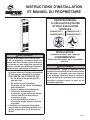
INSTALLATION INSTRUCTIONS
AND OWNER’S MANUAL
Page 1

37134-6-0520Page 2
INTRODUCTION
Always consult your local Building Department regarding regulations,
codes or ordinances which apply to the installation of a vented wall
furnace.
INSTRUCTIONS TO INSTALLER
1. Installer must leave instruction manual with owner after
installation.
2. Installermusthaveownerlloutandmailwarrantycardsupplied
with furnace.
3. Installer should show owner how to start and operate furnace.
WARNING
Any change to this furnace or its control can be dangerous.
This is a heating appliance and any panel, door or guard
removed for servicing an appliance must be replaced prior
to operating the appliance.
To Conserve Gas: Turn off pilot when heater is not in use.
GENERAL INFORMATION
ThisseriesisdesigncertiedinaccordancewithAmericanNational
Standard / CSA Standard Z21.86 and CSA 2.32 by the Canadian
Standards Association, as a Fan Type Vented Wall Furnace and
must be installed according to these instructions.
Any alteration of the original design, installed other than as
shown in these instructions or use with a type of gas not
shown on the rating plate is the responsibility of the person
and company making the change.
IMPORTANT
AllcorrespondenceshouldrefertocompleteModelNo.,SerialNo.
and type of gas.
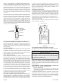
NOTICE:Duringinitialringofthisunit,itspaintwillbakeoutand
smokewilloccur.Topreventtriggeringofsmokealarms,ventilate
the room in which the unit is installed.
INSTALLATION ON RUGS AND TILE
If this appliance is installed directly on carpeting, tile or other
combustiblematerialotherthanwoodooringtheapplianceshall
be installed on a metal or wood panel extending the full width and
depth of the appliance.
Thebasereferredtoabovedoesnotmeanthere-proofbaseas
used on wood stoves. The protection is for rugs that are extremely
thickandlightcoloredtile.
WELL HEAD GAS INSTALLATIONS
Some natural gas utilities use “well head” gas. This may affect
the Btu output of the unit and promote sooting. Units shall not be
converted to use well head gas.
INSTALLATION IN RESIDENTIAL GARAGES
Gas utilization equipment in residential garages shall be installed
so that all burners and burner ignition devices are located not less
than18"(457mm)abovetheoor.
Such equipment shall be located, or protected, so it is not subject
to physical damage by a moving vehicle.
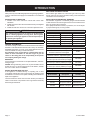
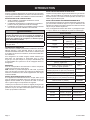
SPECIFICATIONS
Model FAW-40SPP FAW-40IP
Input BTU/HR (KW/H) 40,000 (11.7) 40,000 (11.7)
Height 72 1/2" (84.1mm) 72 1/2" (184.1mm)
Width 14 1/8" (35.9mm) 14 1/8" (35.9mm)
Depth 10 3/8" (26.4mm) 10 3/8" (26.4mm)
Gas Inlet Pipe 1/2" (12.7mm) 1/2" (12.7mm)
Vent Collar Type B Oval
4" (101mm) 4" (101mm)
CFM 275 275
ACCESSORIES
Register,sideoutlet,xedregister SOR-1
Side outlet, 10" (254mm)
maximumextension,xedregister
SOK-1
Rear outlet, 10" (254mm)
maximum extension, adjustable register
ROK-1
Vent enclosure, 24" (609mm)
[for rooms up to 96 1/2" 2451mm) in height]
FVE-24DB
Vent enclosure, 34" (86cm)
[for rooms up to 106 1/2" (2705mm) in height]
FVE-34DB
Vent enclosure, 46" (1168mm)
[for rooms up to 118 1/2" (3009mm) in height]
FVE-46DB
Oval-to-Roundueadapterkit4"(102mm) DV648DBF
CONVERSION KITS
Model Number Description Used On
DV1351 PropanetoNatural FAW40IPXLP-1
DV1349 NaturaltoPropane FAW40IPXNAT-1
DV1347 PropanetoNatural FAW40SPPXLP-1
DV1345 NaturaltoPropane FAW40SPPXNAT-1
INTRODUCTION

37134-6-0520 Page 3
• Due to high temperatures the appliance should be located
out of trafc and away from furniture and draperies.
• Children and adults should be alerted to the hazards of
high surface temperatures and should stay away to avoid
burns or clothing ignition.
• Young children should be carefully supervised when they
are in the same room as the appliance.
• Clothing or other ammable material should not be placed
on or near the appliance.
• Any safety screen or guard removed for servicing an ap-
pliance must be replaced prior to operating the appliance.
• Keep burner and control compartment clean.
• Installation and repair should be done by a QUALIFIED
SERVICE PERSON. The appliance should be inspected
before use and at least annually by a qualied service
person. More frequent cleaning may be required due to
excessive lint from carpeting, bedding materials, etc. It
is imperative that control compartments, burners and
circulating air passageways of the appliance be kept
clean.
• DO NOT put anything around the furnace that will obstruct
the ow of combustion and ventilation air.
• DO keep the appliance area clear and free from combus-
tible material, gasoline and other ammable vapors and
liquids.
• DO examine venting system periodically and replace
damaged parts.
• DO make a periodic visual check of pilot and burners.
Clean and replace damaged parts.
• CAUTION: Pilot hole cover must be kept tightly closed
during operation.
• DO NOT use this heater if any part has been under water.
Immediately call a qualied service technician to inspect
the heater and to replace any part of the control system
and any gas control which has been under water.
• This furnace must not be connected to a chimney ue
serving a separate solid-fuel burning appliance.
• IMPORTANT: This furnace has a washable permanent
type lter in the door which should be cleaned at least
once per year before the heating season. For dirty or
high use areas more frequent cleaning is required.
THIS IS A HEATING APPLIANCE
DONOTOPERATETHISAPPLIANCEWITHOUTFRONTPANELSINSTALLED.
INTRODUCTION (CONT'D)
When an existing Category 1 heater is removed or replaced, the
original venting system may no longer be sized to properly vent the
attached appliances. Instructions shall also indicate effects of an
improperlysizedventingsystem(formationofcondensate,leakage,
spillage, etc.) and shall specify the following test procedure:
WARNING
CARBON MONOXIDE POISONING HAZARD
Failure to follow the steps outlined below for each
appliance connected to the venting system being placed
into operation could result in carbon monoxide poisoning
or death.
The following steps shall be followed for each appliance
connected to the venting system being placed into
operation, while all other appliances connected to the
venting system are not in operation:
1. Seal any unused openings in the venting system.
2. Inspect the venting system for proper size and
horizontal pitch, as required in the National Fuel Gas
Code, ANSI Z223.1/NFPA 54 or the Natural Gas and
Propane Installation Code, CSA B149.1 and these
instructions. Determine that there is no blockage or
restriction, leakage, corrosion and other deciencies
which could cause an unsafe condition.
3. As far as practical, close all building doors and
windows and all doors between the space in which
the appliance(s) connected to the venting system are
located and other spaces of the building.
4. Close replace dampers.
5. Turn on clothes dryers and any appliance not connected
to the venting system. Turn on any exhaust fans, such
as range hoods and bathroom exhausts, so they are
operating at maximum speed. Do operate a summer
exhaust fan.
6. Follow the lighting instructions. Place the appliance
being inspected into operation. Adjust the thermostat
so appliance is operating continuously.
7. Test for spillage from draft hood equipped appliances
at the draft hood relief opening after 5 minutes of main
burner operation. Use the ame of a match or candle.
8. If improper venting is observed during any of the
above tests, the venting system must be corrected in
accordance with National Fuel Gas Code, ANSI Z223.1/
NFPA 54 and/or Natural Gas and Propane Installation
Code, CSA B149.1.
9. After is has been determined that each appliance
connected
to the venting system properly vents when
tested as outlined above, return doors, windows,
exhaust fans, replace dampers and any other gas-red
burning appliance to their previous conditions of use.

37134-6-0520Page 4
SAFETY INFORMATION FOR USERS OF PROPANE GAS
Propane is a ammable gas which can cause res and explo-
sions. In its natural state, propane is odorless and colorless.
You may not know all the following safety precautions which
can protect both you and your family from an accident. Read
them carefully now, then review them point by point with the
members of your household. Someday when there may not
be a minute to lose, everyone's safety will depend on knowing
exactly what to do. If, after reading the following information,
you feel you still need more information, please contact your
gas supplier.
PROPANE GAS WARNING ODOR
If a gas leak happens, you should be able to smell the gas
because of the odorant put in the Propane Gas. That's your
signal to go into immediate action!
• Do not operate electric switches, light matches, use your phone.
Do not do anything that could ignite the gas.
• Get everyone out of the building, vehicle, trailer, or area. Do
that IMMEDIATELY.
• Closeallgastankorcylindersupplyvalves.
• Propane Gas is heavier than air and may settle in low areas
such as basements. When you have reason to suspect a gas
leak,keepoutofbasementsandotherlowareas.Stayout
untilreghtersdeclarethemtobesafe.
• Use your neighbor's phone and call a trained Propane Gas
servicepersonandtheredepartment.Eventhoughyoumay
not continue to smell gas, do not turn on the gas again. Do not
re-enterthebuilding,vehicle,trailer,orarea.
• Finally, lettheservicemanandreghterscheckforescaped
gas. Have them air out the area before you return. Properly
trainedPropaneGasservicepeopleshouldrepair theleak,
thencheckandrelightthegasapplianceforyou.
NO ODOR DETECTED - ODOR FADE
Some people cannot smell well. Some people cannot smell
the odor of the chemical put into the gas. You must nd out if
you can smell the odorant in propane.Smokingcandecrease
your ability to smell. Being around an odor for a time can affect your
sensitivity or ability to detect that odor. Sometimes other odors in
theareamaskthegasodor.Peoplemaynotsmellthegasodoror
theirmindsareonsomethingelse.Thinkingaboutsmellingagas
odorcanmakeiteasiertosmell.
The odorant in Propane Gas is colorless, and it can fade under
some circumstances. For example, if there is an underground
leak,themovementofthegasthroughsoilcanltertheodorant.
Odorants in Propane Gas also are subject to oxidation. This fading
canoccurifthereisrustinsidethestoragetankorinirongaspipes.
The odorant in escaped gas can adsorb or absorb onto or into
walls, masonry and other materials and fabrics in a room. That will
takesomeoftheodorantoutofthegas,reducingitsodorintensity.
Propane Gas may stratify in a closed area, and the odor intensity
could vary at different levels. Since it is heavier than air, there may
be more odor at lower levels. Always be sensitive to the slightest gas
odor.Ifyoudetectanyodor,treatitasaseriousleak.Immediately
go into action as instructed earlier.
SOME POINTS TO REMEMBER
• Learn to recognize the odor of Propane Gas. Your local Propane
Gas Dealer can give you a "Scratch and Sniff" pamphlet. Use
ittondoutwhatthepropaneodorsmellslike.Ifyoususpect
thatyourPropaneGashasaweakorabnormalodor,callyour
Propane Gas Dealer.
• Ifyouarenotqualied,donotlightpilotlights,performservice,
ormakeadjustmentstoappliancesonthePropaneGassystem.
Ifyouarequalied,consciouslythinkabouttheodorofPropane
Gas prior to and while lighting pilot lights or performing service
ormakingadjustments.
• Sometimesa basementor aclosed-up house hasa musty
smell that can cover up the Propane Gas odor. Do not try to
lightpilotlights,performservice,ormakeadjustmentsinan
area where the conditions are such that you may not detect
theodoriftherehasbeenaleakofPropaneGas.
• Odor fade, due to oxidation by rust or adsorption on walls of
newcylindersandtanks,ispossible.Therefore,peopleshould
beparticularlyalertandcarefulwhennewtanksorcylinders
areplacedinservice.Odorfadecanoccurinnewtanks,or
reinstalledoldtanks,iftheyarelledandallowedtosettoo
longbeforerelling.Cylindersandtankswhichhavebeenout
of service for a time may develop internal rust which will cause
odor fade. If such conditions are suspected to exist, a periodic
sniff test of the gas is advisable. If you have any question
about the gas odor, call your Propane Gas Dealer. A peri-
odic sniff test of the Propane Gas is a good safety measure
under any condition.
• If, at any time, you do not smell the Propane Gas odorant and
youthinkyoushould,assumeyouhavealeak.Thentakethe
same immediate action recommended above for the occasion
when you do detect the odorized Propane Gas.
• If you experience a complete "gas out," (the container is under
novaporpressure),turnthetankvalveoffimmediately.Ifthe
container valve is left on, the container may draw in some air
throughopeningssuchaspilotlightorices.Ifthisoccurs,some
new internal rusting could occur. If the valve is left open, then
treatthecontainerasanewtank.Alwaysbesureyourcon-
tainer is under vapor pressure by turning it off at the container
beforeitgoescompletelyemptyorhavingitrelledbeforeitis
completely empty.

37134-6-0520 Page 5
VENTILATION AND COMBUSTION AIR
WARNING
Danger of property damage, bodily injury or death, this furnace
and any other fuel burning appliance must be provided with
enough fresh air for proper combustion and ventilation of ue
gases. Most homes will require that outside air be supplied.
Do not draw air from a corrosive environment such as a
workshop or laundry room.
The requirements for providing air for combustion and ventilation are
listedintheNationalFuelGasCodesNFPA54/ANSIZ223.1(inCanada
-CAN/CGAB149).
NOTE:Airrequirementsforoperationofexhaustfans,kitchenventilation
systems,clothesdryers,replaceandanyotherfuelburningorventilating
equipment used in the space must be considered in determining
combustion air requirements.
VENTILATION AIR OPENINGS AND DUCTS
In determining the free area needed consideration must be given to the
blockingeffectoflouvers,grillsorscreensprotectingopenings.
— If a screen is used to cover openings it must not be smaller than
1/4" mesh.
— Use the free area of a louver or grill to determine the size opening
requiredtoprovidethefreeareaspecied.Ifthefreeareaisnot
knownassumea20%freeareaforwoodanda60%freeareafor
a metal louver or grill.
— Ducts must have the same cross sectional area as the free area of
the openings to which they connect.
— The minimum dimension of air ducts must not be less than 3 inches.
INSTALLATION IN AN UNCONFINED SPACE
Anunconnedspaceisanareaincludingallroomsnotseparatedby
doors with a volume greater than 50 cubic feet per 1,000 Btuh of the
combined total input rates of all appliances which draw combustion air
from that space. For example, a space including a water heater rated
at 40,000 Btuh input and a furnace rated at 40,000 Btuh requires a
volume of 4,000 cubic feet (50 x (40 + 40) = 4,000) to be considered
asunconned.Ifthespacehasan8ft.ceiling,theoorareaofthe
space must be 500 sq. ft. In general, particularly in older homes, a
furnaceinstalledinanunconnedspacewillnotrequireoutsideairfor
combustion. However in a "tight" newly constructed home, outside air
may be necessary to insure adequate combustion.
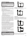
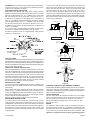
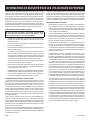
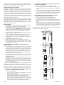
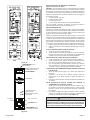
INSTALLATION IN A CONFINED SPACE
Aconnedspaceisanareawithvolumelessthan50cubicfeetper1,000
Btuh of the combined input rates of all appliances drawing combustion
airfromthatspace.Smallareassuchasequipmentroomsareconned
spaces.Furnacesinstalledinaconnedspacewhichsupplyheatedair
to areas outside the space must draw return air from outside the space
throughtightlysealedreturnairducts.Aconnedspacemusthave2
openings into the space for combustion air. One opening must be within
12 inches of the ceiling and the other must be within 12 inches of the
oor.Therequiredsizingoftheseopeningsisdeterminedbywhether
inside or outside air is used to support combustion, the method by which
the air is brought to the space (vertical or horizontal duct) and by the
total input rate of all appliances in the space. See Figure 1.
ALL AIR FROM INSIDE — CONFINED SPACE
Ifcombustionairistakenfromtheheatedspacethe2openingsmust
each have a free area of at least one square inch per 1,000 Btuh of
totalinputofallappliancesintheconnedspacebutnotlessthan100
square inches (645cm
2
) of free area.
Forexample: fora 40,000Btuh furnace onlyinthe connedspace
each opening must be 100 square inches (645cm
2
) each of free area.
WARNING
Combustion air must not be drawn from a heated space which
includes exhaust fans, replaces or other devices that may
produce a negative pressure in the space.
furnace
opening
confined
space
Figure 1
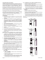
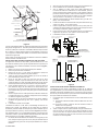
OUTDOOR AIR
Outletandinletaircanbebroughtintotheconnedspaceviaopenings
into a ventilated attic and ventilated crawl space.
furnace
outlet air
inlet air
attic ventilation louvers
crawl space ventilation louvers
Figure 2
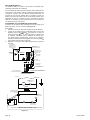
CONFINED SPACE
Outdoor Air Using Vertical or Horizontal Ducts
Ifcombustionairistakenfrom outdoors through verticalducts,the
openings and ducts must have a minimum free area of one square
inch (6.5cm
2
) per 4,000 Btuh of total appliance input. In installations
drawing combustion air from a ventilated attic both air ducts must extend
above the attic insulation.
furnace
outlet air
inlet air ends one foot above floor
vertical
furnace
inlet air duct
outlet air duct
horizontal
Figure 3
Ifcombustionairistakenfromoutdoorsthroughhorizontalductsthe
openings and ducts must have a minimum free area of one square
inch (6.5cm
2
) per 2,000 Btuh of total appliance input.

37134-6-0520Page 6
QUALIFIED INSTALLING AGENCY
Installation and replacement of gas piping, gas utilization equipment or
accessories and repair and servicing of equipment shall be performed
onlybyaqualiedagency.Theterm"qualiedagency"meansany
individual,rm,corporationorcompanywhicheitherinpersonor
through a representative is engaged in and is responsible for (a)
the installation or replacement of gas piping or (b) the connection,
installation, repair or servicing of equipment, who is experienced in
suchwork,familiarwithallprecautionsrequiredandhascomplied
with all the requirements of the authority having jurisdiction.
The installation must conform with local codes or, in the absence of
local codes, with the National Fuel Gas Code, ANSI Z223.1/NFPA
54* Natural and Propane Installation Code, CSA B149.1.
*Available from the American National Standards Institute, Inc., 11
West 42nd St., New York, N.Y. 10036.
CLEARANCES
1. In selecting a location for installation, it is necessary to provide
adequate accessibility clearances for servicing and proper
installation.
2. TheFAW-40canbeattachedtothewallorrecessedintothe
wall up to 9 1/2 inches (24.1cm) in depth. NOTE:
Do not place
combustible header or material on top of unit when
installed in wall. Maintain 3/4" minimum spacing above
heater.
3. The wall in which the furnace is recessed has (0) zero (0mm)
clearance to the furnace sides.
4. Whenusingsidedischargeregisters,SOR-1orSOK-1,the
furnace cannot be recessed into the wall.
5. Clearance to sidewall or combustible material is 4 inches
(10.2cm).
6. Ceiling clearance is 4 inches (10.2cm).
7. Floor and rear wall clearance is (0) zero inches (0mm).
8. Clearance of 18 inches (46cm) is required to adjacent wall or
combustiblematerialwhenushmountedSOR-1,sideoutlet
register is used.
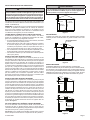
BEFORE INSTALLING CONSIDER THE FOLLOWING VENTING
1. A chimney for residential-type or low-heat gas utilization
equipment shall extend at least 3 feet (914mm) above the
highest point where it passes through a roof of a building and at
least 2 feet (610mm) higher than any portion of building within
a horizontal distance of 10 feet (3m).
2. Thisfurnacemustnotbeconnectedtoachimneyueserving
aseparatesolid-fuelburningappliance.
3. Uninsulated Single-Wall Metal Pipe shall not be used
outdoors in cold climates for venting gas utilization
equipment.
4. ATTENTION! This Fan Type Vented Wall Furnace is equipped
withaventsafetyswitch.Intheeventofspillageofueproducts
due to improper venting the vent safety switch will open, which
results in the main burners to "shut off".
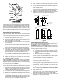
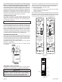
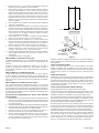
ModelNo.FAW-40maybeventedasshowninFigure 4. The vent
capterminationmustbeatleast12feet(3.7m)abovetheoorand
must exhaust to the outdoors. Clearance to combustible construc-
tionisheldbythexedspacersat1inch(25mm)withB-1or(B-W)
vent pipe. Installation must conform to local codes.
A. 4" (102MM) ROUND (ALL PARTS PURCHASE LOCALLY EX-
CEPT ITEM 2)
1. TypeB-1roundpipe
2. PartNo.DV648DBF,4"(102mm)oval-to-roundueadapter
kit(seeaccessories)
3. SinglestorytypeB-1gasventsrequireabaseplateandone
pair of ceiling plate spacers.
4. Multi-storytypeB-1gasventsrequireabaseplate,onepair
ofceilingplatespacersattherstoorceilingandonepair
ofrestopspacersateachsuccessiveceilinglevel.
B. 4" (102MM) OVAL (ALL PARTS PURCHASE LOCALLY)
1. TypeB-1ovalpipeorB-Wventpipe
2. SinglestorytypeB-1or(B-W)gasventsrequireabaseplate
and one pair of ceiling plate spacers.
3. Multi-storytypeB-1or(B-W)gasventsrequireabaseplate,
onepairofceilingplatespacersattherstoorceilingand
onepairofrestopspacersateachsuccessiveceilinglevel.
C. 4" (102MM) OVAL IN-THE-WALL (ALL PARTS PURCHASE
LOCALLY)
1. TypeB-1ovalpipeorB-Wventpipe
2. TypeB-1ovalelbowsorB-Wovalelbows
3. SinglestorytypeB-1or(B-W)gasventsrequireabaseplate
and one pair of ceiling plate spacers.
4. Multi-storytypeB-1or(B-W)gasventsrequireabaseplate,
onepairofceilingplatespacersattherstoorceilingand
onepairofrestopspacersateachsuccessiveceilinglevel.
Stud space around gas vents must be free of obstructions and
building paper.
4" B-1 OVAL
SPACER
BASEPLATE
4" 45 DEG.
OVAL ELBOW
4" B-1 OVAL
SPACER
BASEPLATE
BASEPLATE
SPACER
4" B-1 OVAL
BRACKET
BASEPLATE
ADAPTER
4" B-1 Round
Figure 4
A
B
C
C

37134-6-0520 Page 7
Figure 5
UseU.L.listedgasventequipmentwheninstallingtheFAW-40.
For vent pipe running through walls, roof, and within one (1) inch
(25mm)ofcombustibleconstruction,useB-1or(B-W)[oneinch
(25mm)clearancetocombustibles]ventpipe.TypeB-2x4orType
B-2x6aretobeusedinconjunctionwithaListedrestopspacer.
Be sure baseplate is attached to top of furnace before inserting unit
into recessed wall installation.
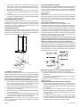
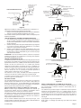
INSTALLING OPTIONAL SIDE OUTLETS
Side outlet register, SOR-1 may be installed on one or both sides
of the furnace at the required clearances of 18 inches (457mm) to
adjacent wall or combustible material as shown in Figure 6.
1. Turn "OFF" all electric power to the furnace.
2. Remove the front panel from the furnace.
3. Remove the (2) #8 x 3/8" (9mm) screws that attach the inner
shield cover plate to the inner shield.
4. Scribe a line between the four dimples on the outer casing side
to form a square.
5. Drill a pilot hole within the scribed square on the outer casing.
Remove the sheet metal within the scribed square with a tin
snips or comparable tool. Attention! Do not cut the electrical
wires located between the outer casing and the inner shield.
6. Insert the 5" x 5" (127mm x 127mm) inner boot through the
outer casing. Align the clearance holes on the inner boot with
the screw holes on the inner shield. Attach inner boot to inner
shield with (2) # 8 x 3/8" (9mm) screws removed in Step 3.
7. Place the register over the 5 1/2" (140mm) square opening with
thelouverssetforthedesireddirectionandmarkthemounting
holes using the register as a template.
8. Drill (2) 1/8" diameter holes in cabinet side and attach the
register with (2) #10 x 1" (25mm) provided screws.
9. InstallationofSOR-1iscompleted.
Sideoutletkit,SOK-1, 10" (254mm) boot assembly with register, for
warm air discharge into an adjoining room may be installed on either
side of the furnace at the required clearance of 4 inches (102mm)
to adjacent wall as shown in Figure 6.
ToinstallSOK-1,pleaseuseSteps1through5intheSOR-1instruc-
tionsforFAW-40furnaces.Now,usethefollowingStepstocomplete
installationoftheSOK-1.
1. Usingtheinnerandouterbootsasholetemplates,markand
drill (4) 1/8" (3mm) diameter holes in the inner shield and (4)
1/8" (3mm) diameter holes in the cabinet side.
2. Locate and cut a 6 3/4" (171mm) square opening through wall.
3. Attach furnace to wall (see Attaching Furnace to Wall).
4. Withfurnaceinplace,aftercheckingalignmentofsideoutlet
opening in wall and furnace, place the 9 3/8" x 9 3/8" (238mm
x 238mm) side outlet wall plate over outer boot, pass the outer
boot through the wall and attach side wall plate to furnace side
of wall with (2) #10 x 1 1/2" (38mm) provided screws.
5. Attach outer boot to the cabinet side with (4) #8 x 1/4" (6mm)
provided screws.
6. Position and attach inner boot to inner shield with (4) #8 x 1/4"
(6mm) provided screws.
7. Place the register over the 6 3/4" (171mm) square opening with
the louvers positioned for the desired discharge direction and
markthemountingholesusingtheregisterasatemplate.
8. Drill (2) 1/8" (3mm) diameter holes in the wall and attach the
register with (2) #10 x 1 1/2" (38mm) provided screws.
9. InstallationofSOK-1iscompleted.
4" MINIMUM TO COMBUSTIBLE
WALL OR SURFACE
CLEARANCE FOR SIDE OUTLET KITS AND REAR REGISTER
KIT TO ADJACENT WALL
4" MINIMUM TO COMBUSTIBLE
WALL OR SURFACE
18" MIN. CLEARANCE TO
WALL OR COMBUSTIBLE
SURFACE USING MODEL
SOR-1 SIDE REGISTER.
WALL
5 1/2"
5 1/2"
UNIT CANNOT BE RECESSED
WHEN SIDE REGISTERS ARE
USED.
WHEN SIDE REGISTERS ARE
NOT USED UNIT MAY BE RECESSED
UP TO 9 1/2"
6 1/4"
10 1/4"
REAR REGISTER OPENING
IN OUTER CABINET
12" 12"
TYPE B-1 OR
B-W OVAL
VENT PIPE
Figure 6
INSTALLING OPTIONAL REAR OUTLET
Rearoutletkit,10"(254mm)bootassemblywithregister,ROK-1
for warm air discharge into an adjoining room.
ATTENTION: Before furnace is attached to the wall, the wall opening
for the rear outlet must be cut, in addition to removal of the outer
andinnercasingknockoutsonfurnace.
1.
The wall opening measurements for the rear outlet are the following.
A. Fromoortobottomofwallopeningis1011/16"(271mm).
B. From bottom of wall opening to top of wall opening is 8 1/2"
(216mm).
C. Wall opening width is 12 1/8" (308mm).
2. Scribealinebetweenthefourdimplesontheoutercasingback
to form a square. Drill a pilot hole within the scribed square
ontheoutercasingback.Removethesheetmetalwithinthe
scribed square with a tin snips or comparable tool.
3. Remove the (4) #8 x 3/8" (9mm) screws that attach the inner
casing close off plate to the inner casing.
4.
Inserttheprivacyshieldthroughtheoutercasingbackandthe
innercasingback.Theprivacyshieldwillbeinfrontoftheinner
casingbackandbehindthecombustionchambertubes.Align
clearance holes on privacy shield with screw holes on inner
casingback.Attachprivacyshieldtoinnercasingbackwith(2)
#8 x 3/8" (9mm) provided. ATTENTION: The (2) #8 x 3/8" (9mm)
screws must be inserted from the front of the furnace.
5. Attach furnace to wall.
6. Align clearance holes on 8" x 12" (203mm x 305mm) boot with
screwholesonoutercasingbackandmarkboottobeush
with wall surface. Remove boot and cut to proper length.
7. Attach8"x12"(203mmx305mm)boottooutercasingback
with (6) #8 x 3/8" (9mm) screws provided.

37134-6-0520Page 8
8. Align clearance holes on 6" x 10" (152mm x 254mm) duct with
screwholesoninnercasingbackandmarkducttobe21/4"
(57mm) shorter than 8" x 12" (203mm x 305mm) boot. Remove
duct and cut to proper length.
9. Attach6"x10"(152mmx254mm)ducttoinnercasingbackwith
(4) #8 x 3/8" (9mm)screws removed in Step 3, 2 on top and 2
on bottom.
10. Insert rear register into 8" x 12" (203mm x 305mm) boot. Attach
rear register to wall with (2) #10 x 1"(25mm) screws provided.
11. InstallationofROK-1iscompleted.
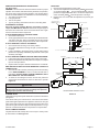
LOCATING FURNACE ON WALL
The furnace is to be located on a wall. The furnace is 14 1/8" (35.9cm)
in width and can be recessed into the wall with typical stud spacing.
A template is provided in furnace carton for locating gas line
connection. Also, refer to Figure 7 for positioning the furnace on
wall and for locating gas line connection.
LOCATING GAS SUPPLY
Thegaslinecanenterthefurnaceeitherthroughtheoororwall.
The gas line opening should be made at this time. Location of the
openingwillbedeterminedbythepositionofoorjoistsandthe
valve and union used for servicing. See Figure 7.
72 3/4"
14 3/8"
CUT OUT OPENING FOR RECESSED MOUNTING
RECESSED MOUNTING
LOCATION
8"
4"
4"
2 1/8"
GAS LINE
HOLE 1 1/4"
ELECTRICAL WIRING HOLE
GAS LI NE/ELECTRICA L OPENINGS FOR
RECESSED AND SURFACE MOUNT
0.0722
0.5249
0.2613
0.2395
0.2624
GAS LINE/ELECTRICAL OPENING
FOR RECESSED AND
SURFACE MOUNTING
SURFACE
MOUNTING
HOLES
OVAL TO ROUND KIT
MOUNTING HOLES
1 1/4" GAS
LINE HOLE
ELECTRICAL
WIRING
HOLE
RECESSED
MOUNTING
HOLES
Figure 7
LOCATING ELECTRIC SUPPLY
A7/8"(22mm)diameterknockoutisprovidedatthebottomofthe
leftandrightsidepanels.Athree-prong(grounding)plugassembly
is located within the control compartment (bottom) of the furnace.
Pleaseremove7/8"(22mm)knockoutfromappropriatesidepanel
when routing plug assembly to an electrical outlet.
INSTALLATION OF THREE-PRONG (GROUNDING) PLUG ASSEMBLY
1. Disconnect nylon cap on 3' (914mm) plug assembly from nylon
plug on wiring harness. Remove 3' (914mm) plug assembly
from control compartment (bottom) of the furnace.
2. Remove7/8"(22mm)knockoutfromappropriatesidepanel.
3. Insert nylon cap on 3' (914mm) plug assembly into the 7/8"
(22mm) hole in the side panel.
4. Connect nylon cap on 3' (914mm) plug assembly to nylon plug
on the wiring harness.
5. Place 7/8" (22mm) strain relief bushing around the cord of the
3' (914mm) plug assembly. Insert 7/8" (22mm) strain relief
bushing into the 7/8" (22mm) hole in the side panel.
ATTENTION! The 7/8" (22mm) strain relief bushing is located
within the same yellow envelope as the Installation Instructions
and Owner's Manual.
ATTACHING FURNACE TO WALL
When attaching furnace to the wall remove that portion of baseboard
and molding on the wall which is behind the furnace. Attach furnace
to wall, at the outer casing top, with (2) toggle bolts provided and
tooor,attheoutercasingbottom,with(2)#10x11/2" (38mm)
screws provided.
GAS SUPPLY
Checkalllocalcodesforrequirements,especiallyforthesizeand
typeofgassupplylinerequired.OnNaturalGaslineslessthan
75' (22.9m) long, use 1/2" (13mm) pipe; on longer runs, use 3/4"
(19mm) iron pipe or equal. On Propane Gas lines please consult
Propane Gas supplier.
INSTALLING A NEW MAIN GAS SHUT-OFF
Eachapplianceshouldhaveitsownmanualgasshut-off.
Amanualmaingasshut-offshouldbelocatedinthevicinityofthe
unit. Where none exists, or where its size or location is not adequate,
contact your local authorized installer for installation or relocation.
Compounds used on threaded joints of gas piping shall be resistant
totheactionofliqueedpetroleumgases.Thegaslinesmustbe
checkedforleaksbytheinstaller.Thisshouldbedonewithasoap
solution watching for bubbles on all exposed connections, and if
unexposed, a pressure test should be made.
Never use an exposed ame to check for leaks. Appliance must
be disconnected from piping at inlet of control valve and pipe
capped or plugged for pressure test. Never pressure test with
appliance connected; control valve will sustain damage!
A gas valve and ground joint union should be installed in the gas
line upstream of the gas control to aid in servicing. It is required by
theNationalFuelGasCodethatadriplinebeinstallednearthegas
inlet. This should consist of a vertical length of pipe tee connected
into the gas line that is capped on the bottom in which condensation
and foreign particles may collect.
Figure 8
METHOD OF INSTALLING A TEE FITTING SEDIMENT TRAP
The use of the following gas connectors is recommended:
— ANSZ21.24ApplianceConnectorsofCorrugatedMetalTubing
and Fittings
— ANSZ21.45AssembledFlexibleApplianceConnectorsofOther
ThanAll-MetalConstruction
The above connectors may be used if acceptable by the authority
having jurisdiction.
PRESSURE TESTING OF THE GAS SUPPLY SYSTEM
1. Tochecktheinletpressuretothegasvalve,a1/8"(3mm)N.P.T.
plugged tapping, accessible for test gauge connection, must
be placed immediately upstream of the gas supply connection
to the appliance.
2. The appliance and its individual shut-off valve must be
disconnected from the gas supply piping system during any
pressure testing of that system at test pressures in excess of
1/2psig(3.5kPa).
3. The appliance must be isolated from the gas supply piping
systembyclosingitsindividualmanualshut-offvalveduring
any pressure testing of the gas supply piping system at test
pressuresequaltoorlessthan1/2psig(3.5kPa).

37134-6-0520 Page 9
To clean burner port disconnect the gas supply to the valve, and
remove the screws fastening the burner door. After removing the
burner door from the burner box, remove each main burner. Pilot
mounting bracket willneed to be unscrewed andmoved out of
the way to remove all burners. Burners can be blown out using
compressed air or by blowing through them. Be sure there is no lint
orforeigndebrisblockingtheburnerports.Reassembleusingthe
same screws earlier removed and locate pilot in the same position
as before and noted above.
SPARK
ELECTRODE
THERMOCOUPLE
PILOT
BURNER
STANDING PILOT
PILOT LOCATION END VIEW
PILOT SHIELD
THERMOCOUPLE
S
PARK
ELECTRODE
STANDING PILOT SHOWN
BURNER
PILOT
HOT SURFACE
IGNITOR
FLAME
ROD
GROUND
ELECTRODE
3/8" TO 1/2"
PILOT FLAME
IP-MODEL PILOT
Figure 10
Figure 11
CLEANING COMBUSTION (EXCHANGER) ASSEMBLY
A QUALIFIEDSERVICEPERSON should remove the combustion
(exchanger)assemblyanduebafes.Applyairpressuretothe
insideofthecombustion(exchanger)assemblyanduebafesin
order to clear all passageways.
OILING THE MOTOR
The fan motor should be cleaned and oiled once each heating
season. Oil holes are located on the top at each end of the motor.
Use a few drops of #10 motor oil. To clean the motor, blow air
through its ventilation openings with a vacuum cleaner or low
pressure air source.
WIRING
The appliance, when installed, must be electrically grounded in
accordance with local codes or, in the absence of local codes, with
the National Electrical Code, ANSI/NFPA 70 or Canadian Electrical
Code, CSA C22.1, if an external electrical source is utilized. This
appliance is equipped with a three-prong [grounding] plug for
ATTENTION! If one of the above procedures results in pressures in
excessof1/2psig(14"w.c.)(3.5kPa)ontheappliancegasvalve,
it will result in a hazardous condition.
CHECKING MANIFOLD PRESSURE
Both Propane and Natural Gas valves have a built-in pressure
regulatorinthegasvalve.NaturalGasmodelswillhaveamanifold
pressureofapproximately4.0"w.c.(.996kPa)atthevalveoutlet
with the inlet pressure to the valve from a minimum of 5.0" w.c.
(1.24kPa)for thepurpose ofinput adjustmenttoa maximumof
10.5"w.c.(2.615kPa).PropaneGasmodelswillhaveamanifold
pressure approximately 10.0" w.c. (2.49kPa) at the valve outlet
with the inlet pressure to the valve from a minimum of 11.0" w.c.
(2.739kPa)forthepurposeofinputadjustmenttoamaximumof
13.0"w.c.(3.237kPa).
A 1/8" (3mm) N.P.T. plugged tapping, accessible fortest gauge
connection, is located on the outlet side of the gas control.
Thebuilt-inregulatorcomesonatapproximately 1/4thpressure
and full on in 10 seconds.
Figure 9
HIGH ALTITUDES
For altitudes/elevations above 2,000 feet (610m), input ratings should
be reduced at the rate of 4 percent for each 1,000 feet (305m) above
sea level. For Canadian high altitude applications, this appliance is
suitable for installation at elevations between 0 feet (0m) and 4,500
feet (1,372m) without change.
PIEZO PILOT IGNITOR INSTRUCTIONS
Depressingtheredbuttoncompletelycausesasparktooccuratthe
pilot. This is a substitute for a match which requires opening the pilot
hole cover. To light the pilot, it is important that the electrode be 1/8"
(3mm)fromthethermocouple.Thesparkmustoccuratthepoint
theburneramehitsthethermocouple.Theendoftheelectrode
will be red hot with the pilot on.On a new installation with air in the
gas line, it is suggested that a match be used. The match will light
the pilot faster than the piezo under this condition.
PROPER PILOT FLAME
The correctpilot ame(Figure 10) will be blue, extending past
thethermocouple.Theamewillsurroundthethermocouplejust
below the tip.
NaturalGaspilotsrequireadjustingwhentheinletgaspressure
isabove5"w.c.(1.245kPa).Removethepilotcoverscrewonthe
control valve (Figure 9),andturntheadjustmentscrewclockwiseto
reduceame.Replacepilotcoverscrewtoeliminategasleakage.
Propane Gas will not require adjustment.
Afteruse,cleaningmayberequiredfortheproperame.
PROPER MAIN BURNER FLAME
Thecorrect amewillbe ashort, blueinnerame withamuch
larger,lightblue,outerame.Theburnerdoesnothaveaprimary
airadjustment.Theamewillbecorrectifthefactory-setpressure
andoriceopeningareused.Afterthefurnacehasbeenoperating,
theburnerportsmaybeblockedbyforeignmattercarriedinby
combustion air. Therefore, cleaning of the burner may be needed
forproperame.
IP-MODELPILOT
STANDINGPILOT
PILOTLOCATIONENDVIEW
STANDINGPILOTSHOWN

37134-6-0520Page 10
your protection against shock hazard and should be plugged
directly into a properly grounded three-prong receptacle. Do
not cut or remove the grounding prong from this plug. For an
ungrounded receptacle, an adapter, which has two prongs and a
wire for grounding, can be purchased, plugged into the ungrounded
receptacle and its wire connected to the receptacle mounting screw.
With this wire completing the ground, the appliance cord plug can
be plugged into the adapter and be electrically grounded. A 7/8"
(22mm) hole is provided in the junction box for use with a conduit
connector if local codes require this type of protection.
OPERATING INSTRUCTIONS
This heater is equipped to operate manually. Remove the front
doortogainaccesstothevalve.TurnthegascontrolfromtheON
position to PILOT to turn the heater off, or to the OFF position to
turn the heater and pilot off.
To Conserve Gas: Turn off pilot when heater is not in use.
INSTALLING ON/OFF DEVICE
To install an On/Off device (such as a wall switch, remote, toggle
switch or thermostat), remove the wire nut from the two wires from
thevalve.RunadditionalwirefromthevalvewirestotheON/OFF
device. Install the On/Off device in the same room as the furnace
following the installation instructions supplied with it. In the absence
ofinstructions,installtheOn/Offdevice4to5feetabovetheoor
on an interior wall not affected by another heating source (i.e. stove
or water heater) or the temperature of an adjoining room.
INSULATED VENT ENCLOSURE
Ventedwallfurnacesinstalledinbuildingswithatroofscanhave
poor venting. The cold vent pipe will have a delay in proper venting
and cause the wall furnace to shut "OFF" by the vent safety switch.
Topreventdelayedventingaswellascondensationofueproducts
an insulated vent enclosure is recommended.
Use type B vent pipe and maintain at least a one inch (25mm)
clearance to combustibles.
Use metal thimble to protect vent pipe as it passes through
combustibles.
Figure 12
VENT SAFETY SHUT-OFF SYSTEM
This appliance must be properly connected to a venting system.
Thisapplianceisequippedwithaventsafetyshut-offsystem.
WARNING
Operation of this wall furnace when not connected to
a properly installed and maintained venting system or
tampering with the vent safety shut-off system can result in
carbon monoxide (CO) poisoning and possible death.
This furnace is equipped with a manual reset vent safety switch.
Themanualresetventsafetyswitchwillcausegasowtothemain
burnersto"shutoff"duetoimproperventingorablockedue.
To reset the manual reset vent safety switch:
1. Remove front panel.
2. Depress manual reset button. The manual reset vent safety
switch is located on the draft diverter.
3. Replace front panel.
If the manual reset vent safety switch continues to "shut off" the
gasowtothemainburnersaqualiedservicepersonmustbe
contactedtoinspectforimproperventing,blockageintheventpipe
or the manual reset vent safety switch for being defective.
TRANSFORMER
——— —— —————————————————— —
TRANSFORMATEUR
SPT-3 CORDSET
——— —— ——————————————— —
CORDON SPT-3
WHITE (BLANC)
BLACK (NOIR)
MOTOR
————— —————
MOTEUR
YELLOW (JAUNE)
RED/WHT (ROUGE/BLANC)
YELLOW
JAUNE
WHITE
BLANC
BLACK
NOIR
RED/WHT
ROUGE/BLANC
TRANSFORMER
——— —— —————————————————— —
TRANSFORMATEUR
24 VOLTS
MOTOR
————— —————
MOTEUR
AUTO FAN
——— —— ——————————— —
VENTILATEUR
AUTO
120 VOLTS
BLACK
NOIR
RED/WHT
ROUGE/BLANC
LOW VOLTAGE (BAS VOLTAGE)
120 VOLTS
JUNCTION BOX
—— —— ——— —————————————— ——
BOÎTE DE JONCTION
RED/WHT
ROUGE/BLANC
GAS VALV E
——— —— ————————————— —
VALVE DE GAZ
BLACK (NOIR) BLACK (NOIR)
RED/WHT (ROUGE/BLANC)
RED/WHT (ROUGE/BLANC)
LIMIT CONTROL
——— — ——————————————— —
CONTRÔLE
LIMITE
WIRING DIAGRAM
————————————————————
CÂBLAGE DE DIAGRAMME
VENT SAFETY
——— —— ——————————— —
SÛRETÉ DE
L’ÉVENT
AUTO FAN
——— —— ——————————— —
VENTILATEUR
AUTO
IF ANY OF THE ORIGINAL WIRE AS SUPPLIED
WITH THIS UNIT MUST BE REPLACED, IT MUST
BE REPLACED WITH 150°C THERMOPLASTIC
4/64 THICK OR ITS EQUIVALENT.
120V. 60Hz. LESS THAN 3 AMPS
S´IL YAUN FIL ORIGINAL FOURNI AVEC
L´APPAREIL QUI DOIT ÊTRE REMPLACÉ. IL DOIT
ÊTRE REMPLACÉ AVEC UN ÉQUIVALENT À FIL
4/64” THERMOPLASTIQUE 150°C.
120V. 60Hz. MOINS DE 3 AMPS.
—————— ———————————————————————————————————————————————
LADDER WIRING DIAGRAM
——————————————————————————
ÉCHELLE ÉLECTRIQUE
SCHÉMATIQUE
BLK (NOIR)
GRN (VERT)
WHT (BLANC)
SPP UNITS
GAS VALV E
——— —— ————————————— —
VALVE DE GAZ
LIMIT CONTROL
——— — ——————————————— —
CONTROL DE
TOLERANCE
BLACK
NOIR
BLACK
NOIR
VENT SAFETY
——— — ——————————————— —
SÛERTÉ DE
L’ÉVENT
WIRE NUT / ON/OFF DEVICE
——— — —————————————————————————————— —
FILS TORSADÉS / ON/OFF
PÉRIPHÉRIQUES
WIRE NUT / ON/OFF DEVICE
——— — —————————————————————————————— —
FILS TORSADÉS / ON/OFF
PÉRIPHÉRIQUES
LIMIT CONTROL
——— — ——————————————— —
CONTRÔLE
LIMITE
TRANSFORMER
——— —— —————————————————— —
TRANSFORMATEUR
SPT-3 CORDSET
——— —— ——————————————— —
CORDON SPT-3
WHITE (BLANC)
BLACK (NOIR)
MOTOR
————— —————
MOTEUR
WIRING DIAGRAM
————————————————————
CÂBLAGE DE DIAGRAMME
VENT SAFETY
——— —— ——————————— —
SÛRETÉ DE
L’ÉVENT
YELLOW (JAUNE)
AUTO FAN
——— —— ——————————— —
VENTILATEUR
AUTO
IF ANY OF THE ORIGINAL WIRE AS SUPPLIED
WITH THIS UNIT MUST BE REPLACED, IT MUST
BE REPLACED WITH 150°C THERMOPLASTIC
4/64 THICK OR ITS EQUIVALENT.
120V. 60Hz. LESS THAN 3 AMPS
S´IL YAUN FIL ORIGINAL FOURNI AVEC
L´APPAREIL QUI DOIT ÊTRE REMPLACÉ. IL DOIT
ÊTRE REMPLACÉ AVEC UN ÉQUIVALENT À FIL
4/64” THERMOPLASTIQUE 150°C.
120V. 60Hz. MOINS DE 3 AMPS.
—————— ———————————————————————————————————————————————
RED/WHT (ROUGE/BLANC)
RED (ROUGE)
LADDER WIRING DIAGRAM
——————————————————————————
ÉCHELLE ÉLECTRIQUE
SCHÉMATIQUE
RED/WHT
ROUGE/BLANC
TRANSFORMER
——— —— —————————————————— —
TRANSFORMATEUR
24 VOLTS
120 VOLTS
RED/WHT
ROUGE/BLANC
BLACK
NOIR
RED/WHT
ROUGE/BLANC
BLACK
NOIR
LOW VOLTAGE (BAS VOLTAGE)
120 VOLTS
JUNCTION BOX
—— —— ——— —————————————— ——
BOÎTE DE JONCTION
RED/WHT
ROUGE/BLANC
VENT SAFETY
——— — ——————————————— —
SÛERTÉ DE
L’ÉVENT
LIMIT SWITCH
——— — ——————————————— —
CONTRÔLE DE
TOLÉRANCE
BLK (NOIR)
GRN (VERT)
WHT (BLANC)
BLK (NOIR)
BLK (NOIR)
BLK (NOIR)
IP UNITS
YELLOW
JAUNE
WHITE
BLANC
BLACK
NOIR
MOTOR
————— —————
MOTEUR
AUTO FAN
——— —— ——————————— —
VENTILATEUR
AUTO
ON/OFF DEVICE
——— — ——————————————— —
ON/OFF
PÉRIPHÉRIQUES
WIRE NUT / ON/OFF DEVICE
——— — —————————————————————————————— —
FILS TORSADÉS / ON/OFF
PÉRIPHÉRIQUES
WIRE NUT
——— — ——————————————— —
FILS TORSADÉS
SPP IP
Figure 13
BURNER BOX
GAS VALVE
JUNCTION BOX-
TRANSFORMER
LIMIT SWITCH
FAN SWITCH
VENT LIMIT SWITCH
FLUE CONNECTOR
FAN
P
IEZO
IGNITOR
DRAFT DIVERTER
Figure 14

37134-6-0520 Page 11
TO ADJUST:
1. Remove the pilot adjustment cover screw.
2. Turntheinneradjustmentscrewclockwise
to decrease
orcounterclockwise
toincreasepilotame.Pilotad-
justmentisshippedatfullowrate.Turntheinneradjustment
screwclockwise
if the inlet pressure is too high.
3. Replace the cover screw after the adjustment to prevent gas
leakage.
ON
OFF
IGNITOR
CONTROL
INLET PRESSURE TAP
OUTLET PRESSURE TAP
PILOT ADJUSTMENT-
UNDER CAP SCREW
PILOT OUTLET
PRESSURE REGULATOR
ADJUSTMENT-UNDER CAP
SCREW
GAS FLOW
IGNITOR
CONTROL
TO 24 V. THERMOSTAT
TO 24 V. COMMON ON TRANSFORMER
TO 24 V."HOT" ON TRANSFORMER
WIRING
I P-MODEL GAS VALVE AND WIRING
IGNITOR-PILOT ASSY.
FAN
SWITCH
MOTOR
HONEYWELL IP
SMART VALVE
120 VAC
LIMIT
CONTROL
VENT SAFETY
LIMIT
THERMOSTAT
40 VA TRANSFORMER
24 VAC
120VAC
VALVE CONTROL
CONNECTOR
L1 "HOT"
L2 NEUTRAL
LADDER WIRING DIAGRAM-IP VALVE
Figure 15
SERVICE AND MAINTENANCE SUGGESTIONS
Call Serviceman
GENERAL: Allfurnaceshavebeenre-testedtocheckforproper
operation.Thisincludes,mainburnerame,pilotame,fanoperation,
fan control, limit control and valve operation. If the furnace fails to
functiononinitialinstallation,itisadvisabletore-checkthefollowing:
1. 115 volts to the junction box.
2. Inlet gas pressure.
3. The 24 volt system.
4. Type of gas being used and that shown on the rating label.
STANDING PILOT MODEL
Servicing the Pilot and Main Burners, Pilot Orice, Thermo-
couple, and Main Burner Orices: Disconnect the gas supply at
the inlet to the control valve. Then remove the burner door to gain
access to the above listed components.
IF ELECTRODE DOES NOT PRODUCE SPARK:
1. Checkwireconnections.
2. Checkgapforpilotburnertotheelectrodetip.Shouldbebetween
1/8" (3mm) and 3/16" (5mm). Electrode wire and tip must be
more than 1/4" (6mm) away from all other metal components.
IF PILOT DOES NOT LIGHT BY ANY MEANS:
1. Checkvalveknobforbeinginthe"Pilot"position.
2. Checkpilotadjustmentforbeingfullopen(counterclockwise
to open).
3. Ifgasisavailableinthesupplytubing,thepilotoriceand/or
pilot burner is probably restricted by a spider web. Clean pilot
assembly and relight.
IF PILOT DOES NOT REMAIN ON AFTER RELEASING KNOB:
1. Follow instructions and hold button down longer and harder.
2. Determineifpilotameextendspastthermocouple;ifnot,adjust
input or clean pilot burner.
3. Replace thermocouple if millivolts read less than 15 millivolts.
MAIN GAS VALVE DOES NOT OPEN WHEN GAS CONTROL IS
TURNED TO ON:
1. Checkfor24voltstovalvebyremovingonewireandtouching
to the SAME TERMINAL it was on. Terminal should have a
lightspark.DO NOT SHORT ACROSS TERMINALS, AS IT
WILL BURN OUT THE GAS CONTROL.
2. Tocheckforlinevoltagetofurnace,removefrontpaneland
shortacrosstwo-terminalfancontroltoallowfantooperate
Figure 14.
CAUTION
Label all wires prior to disconnection when servicing controls.
Wiring errors can cause improper and dangerous operation.
Verify proper operation after servicing.
IP-MODEL PILOT
This heater is using a Honeywell "Smart Valve" system for intermittent
pilot ignition.
On a call for heat by the control turns on a 24 volt mini hot surface
ignitor which lights a pilot that in turn lights the main burner. The gas
valve used in this system is a step opening which opens at a lower
pressure for ignition and then steps to a full inlet pressure of 4" H
2
O
pressureonNaturalGasand10"H
2
0 pressure on Propane Gas.
PILOT FLAME ADJUSTMENT
Thepilotameshouldenvelop3/8to1/2inch(10to13mm)ofthe
tipoftheamerod.See Figure 10.

37134-6-0520Page 12
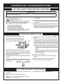
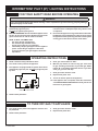
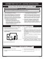
A. This appliance is equipped with an ignition device which
automatically lights the pilot.
Do not try to light the pilot by hand.
B. BEFORE OPERATING smell all around the appliance area
for gas. Be sure to smell next to the oor because some
gas is heavier than air and will settle on the oor.
WHAT TO DO IF YOU SMELL GAS
• Do not try to light any appliance.
• Do not touch any electrical switch;
do not use any phone in your building.
• Immediately call your gas supplier from a neighbor's
phone. Follow the gas supplier's instructions.
• If you cannot reach your gas supplier, call the re
department.
C. Use only your hand to slide the gas control knob. Never
use tools. Force or attempted repair may result in a re
or explosion.
D. Do not use this appliance if any part has been under water.
Immediately call a qualied service technician to inspect
the appliance and to replace any part of the control system
and any gas control which has been under water.
STANDING PILOT
-
LIGHTING INSTRUCTIONS
FOR YOUR SAFETY READ BEFORE OPERATING
1. Turn off all electric power to appliance if service is to be
performed .
2. Remove control access panel (front panel).
3. Push in gas control knob slightly and turn clockwise
to "OFF." Do not force.
4. Replace control access panel (front panel).
TO TURN OFF GAS TO APPLIANCE
1. STOP! Read the safety information above.
2. Turn off all electric power to the appliance.
3. Remove control access panel (front panel).
4. Turn gas control knob clockwise to "OFF
GAS CONTROL SHOWN IN “OFF” POSITION
5. Wait ten (10) minutes to clear out any gas. Then smell
for gas, including near the oor. If you smell gas, STOP!
Follow "B" in the safety information above. If you don't
smell gas, go to the next step.
6. Remove the pilot access cover located on the combustion
chamber.
7. Find pilot - follow metal tube from gas control. The pilot
is located between the two burner tubes behind the pilot
access cover.
8. Turn gas control knob counterclockwise
to
"PILOT."
9.
Push and hold red reset button down completely and
repeatedly push the ignitor button until the pilot burner
is lit. Pilot may also be lit with a match. Continue to hold
the red reset button down for about one (1) minute after
the pilot is lit. Release button and it will pop back up. Pilot
should remain lit. If it goes out, repeat steps 5 through 10.
• If button does not pop up when released, stop and
immediately call a qualied service technician or gas
supplier.
• If the pilot will not stay lit after several tries, turn the
gas control knob to "OFF" and call your service tech-
nician or gas supplier.
10. Replace pilot access cover.
11. Turn gas control knob counterclockwise
to "ON."
12. Replace control access panel (lower front panel).
13. Turn on all electric power to the appliance.
OPERATING INSTRUCTIONS
WARNING
If you do not follow these instructions exactly, a re or explosion may result causing property damage,
personal injury or loss of life.

37134-6-0520 Page 13
1. STOP! Read the safety information above.
2. Turn off all electric power to the appliance.
3. This appliance is equipped with an ignition device which
automatically lights the pilot. Do not try to light the pilot
by hand.
ON
OFF
IGNITOR
CONTROL
GAS FLOW
GAS VALVE SHOWN IN OFF POSITION
HONEYWELL IP SMART VALVE
4. Remove front panel door.
5. Slide gas control switch to "OFF."
6. Wait ten (10) minutes to clear out any gas. Then smell
for gas, including near the oor. If you smell gas, STOP!
Follow "B" in the safety information above. If you don't
smell gas, go to the next step.
7. Slide gas control switch to "ON".
8. Replace front panel door.
9. Turn on all electric power to the appliance.
10. If the appliance will not operate, follow the instructions
"TO TURN OFF GAS TO APPLIANCE" and call your service
technician or gas supplier.
A. This appliance is equipped with an ignition device which
automatically lights the pilot.
Do not try to light the pilot by hand.
B. BEFORE OPERATING smell all around the appliance area
for gas. Be sure to smell next to the oor because some
gas is heavier than air and will settle on the oor.
WHAT TO DO IF YOU SMELL GAS
• Do not try to light any appliance.
• Do not touch any electrical switch;
do not use any phone in your building.
• Immediately call your gas supplier from a neighbor's
phone. Follow the gas supplier's instructions.
• If you cannot reach your gas supplier, call the re
department.
C. Use only your hand to slide the gas control knob. Never
use tools. Force or attempted repair may result in a re
or explosion.
D. Do not use this appliance if any part has been under water.
Immediately call a qualied service technician to inspect
the appliance and to replace any part of the control system
and any gas control which has been under water.
INTERMITTENT PILOT (IP)
-
LIGHTING INSTRUCTIONS
FOR YOUR SAFETY READ BEFORE OPERATING
OPERATING INSTRUCTIONS
1. Turn off all electric power to the appliance if service is to
be performed.
2. Remove front panel door.
3. Slide gas control switch to "OFF."
4. Replace front panel door.
TO TURN OFF GAS TO APPLIANCE
WARNING
If you do not follow these instructions exactly, a re or explosion may result causing property damage,
personal injury or loss of life.

37134-6-0520Page 14
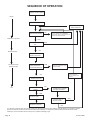
START
System Check
Trial for
Ignition
Main Burner
Operation
END
Pilot Valve Opens
Ignitor Powered
Flame Signal
Detected
Call for Heat
Ignitor OFF
Main Valve Opens
Internal Check
OK
Pilot Light and Flame is
Sensed During Trial For
Ignition (1)
Apply 24 VAC
To Appliance
Main Pilot Valves
Close
Call for Heat Ends
Flame Signal
Lost?
Pilot Valve Ignition OFF
Wait for Flame Signal to
Disappear
Pilot Valve Closes
Ignition OFF
Main Pilot
Valves Close
Flame Lost More
Than 5Times in
One Call for Heat
5 Minute Retry Delay
3 Second Flame Recycle
Delay
YES
NO
NO
YES
NO
YES
YES
NO
YES
NO
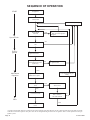
(1) Ignitor will turn OFF about 30 seconds into the trial for ignition if the pilot flame has not lit. It will turn back ON for the final 30 seconds
of the 90 second trial for ignition. The pilot valve will be energized during the entire trial for ignition. This is normal operation for this gas
ignition system.
SEQUENCE OF OPERATION

37134-6-0520 Page 15
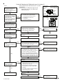
START
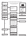
IP SYSTEM TROUBLESHOOTING SEQUENCE
Turn OFF Gas Supply
Disconnect System Control
Harness
Set Gas Control to Call for
Heat
Check for Proper Voltage at
Control Harness (See Inset A-
Vo ltageShouldbe 24V
Between Switch and 24V
Common, and 24V Between
24V Common and 24V Hot.)
Plug Harness into SmartValve
Control
Wait for Internal Check Delay
(SV9501)
Igniter Warms UP and Glows
Red
Note: Igniter Will Cycle OFF
and Back ON Once During the
90 Second Ignition Trial
Turn On Gas Supply
Pilot Burner Lights
Main Valve Opens and
Main Burner Lights
System is Okay
Check
Line Voltage Power
Low Voltage Transformer
Limit Controller
Wiring
Unplug Pilot Burner Cable.
Measure Voltage at SmartValue HSI
Element Output (See Inset B) 24V
Nominal
Replace Igniter/Flame Rod
Assembly
Reconnect Pilot Burner Cable
Check that Pilot Gas is Flowing
Wait to Assure Pilot Gas Tubing is
Purged.
Measure Voltage Between 24V Hot
and 24V Common Leads to
SmartValve Control. Must Measure
at Least 19.5 VAC with Igniter
Powered. See InsetAto Identify
Proper Lead. This Check Must be
Done with the SmartValve Control
Connected and Igniter Powered.
Replace Igniter/Flame Rod
Assembly
Check that Pilot Flame Makes
Good Contact with Pilot Burner
Flame Rod
Check for Good Electrical
Connection Through the Pilot
Tubing
If Both of the Above are Good,
Replace Igniter/Flame Rod
Cycle Gas Control OFF and Back
ON
Main Burner Lights
YES
NO
NO
NO
NO
YES
YES
YES
Replace SmartValve Control
Reconnect Pilot Burner Cable
NO
Replace SmartValve Control
NO
Check Transformer and Line Volt
Supply
NO
Replace SmartValve Control
NO
SmartValve System Troubleshooting Sequence
Note: Before Troubleshooting, Become Familiar
with the Sequence of Operation
TM
HSI
Terminals
INSET B
End View
of Control
Harness
Connector
EFT
Output
24 Volt
Hot
24
Volts
24 Volt
Common
24
Volts
24 Volt
INSET A

37134-6-0520Page 16
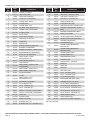
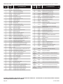
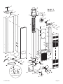
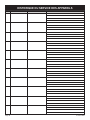
USE ONLY MANUFACTURER'S REPLACEMENT PARTS. USE OF ANY OTHER PARTS COULD CAUSE INJURY OR DEATH.
PLEASE NOTE: When ordering parts, it is very important that part number and description of part coincide.
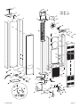
INDEX
NO.
PART
NO.
DESCRIPTION
1 WFA115 GASKET-HEADER
2 DV1247 TOP PLATE (USA)
2 15668 TOPPLATE(CANADA)
3 R3165 DOOR CLIP (2 REQUIRED)
4 39476 CASINGSIDE-RIGHT
5 DV1203 CASINGBACK
6 39476 CASINGSIDE-LEFT
7 DV1248 AIRDROP(INCLUDESNO.51)
8 DV1231 TURBULATOR (3 REQUIRED)
9 DV1250 DIVIDER PLATE
10 DV1234 OUTLET BOX
11 DV1225 OUTLET BOX COVER
12 R3177 VENTSAFETYSWITCH
13 R3161 FANBLADE
14 R3166 FANMOTOR
15 DV1246 MOTORMOUNTINGBRACKET
16 R1536 BUSHING(5REQUIRED)
17 R1499 RUBBER GROMMET (4 REQUIRED)
18 R1454 BRASSBUSHING(4REQUIRED)
19 R3164 DOOR CLIP (2 REQUIRED)
20 DV1251
INNERSHIELD-RIGHT
(INCLUDESNO.23)
21 R6176 FANCONTROLSWITCH
22 R3176 LIMIT SWITCH
23 DV1253
INNERSHIELDCOVERPLATE
(2 REQUIRED)
24 DV1254 INNERSHIELDFRONT(SPP)
24 33416 INNERSHIELDFRONT(IP)
25 R3163 FILTERRETAINER
26 R3162 FILTER
27 DV1252
INNERSHIELD-LEFT
(INCLUDESNO.23)
28 DV1256 EXCHANGERASSEMBLY
29 DV1235 PILOT BRACKET (IP)
30 R3232 PILOT-NATURAL (IP)
30 R3233 PILOT-PROPANE (IP)
31 P8851 ORIFICE-NATURAL (3 REQUIRED)
31 P8860 ORIFICE-PROPANE (3 REQUIRED)
32 DV1236 MANIFOLD
33 DV1258 CASINGFRONT
34 P112 MANIFOLDUNION
35 R1109 BUSHING(3/8x1/2)
35 R9502 BUSHING(3/8x3/4)-NATURAL(IP)
36 R5655 GASVALVE-PROPANE (SPP)
36 R2148 GASVALVE-NATURAL(SPP)
36 R3170 GASVALVE-NATURAL(IP)
36 R3171 GASVALVE-PROPANE (IP)
37 R2708 PIEZOIGNITOR(SPP)
38 FF160 PIEZO BRACKET (SPP)
39 DV1318 OBSERVATIONHOLECOVERPLATE
40 DV1242
BURNERCOMPARTMENTFRONT
(SPP)
41 DV1237 BURNERCOMPARTMENTBODY
42 M148 MANIFOLDGASKET
43 GWT168 AIRSHUTTERFRONT(PROPANE)
44 GWT169 AIR SHUTTER REAR (PROPANE)
45 R3031 BURNER(3REQUIRED)
46 DV1239 BURNERBRACKET
47 UH452
TRANSFORMERMOUNTING
BRACKET (IP)
47 UH810
TRANSFORMERMOUNTING
BRACKET (SPP)
48 R1995 TRANSFORMER(SPP)
48 R998 TRANSFORMER(IP)
49 UH451 JUNCTIONBOXCOVER
50 DV572 JUNCTIONBOX
51 DV1260 COVERPLATE-AIRDROP
52 R1410 BUSHING
53 R690 CORD SET
54 R1515 BUSHING
55 DV1215 BOTTOM PLATE
56 R3034 PILOT-NATURAL(SPP)
56 R3035 PILOT-PROPANE (SPP)
57 GWT021 PILOT BRACKET (SPP)
58 R3180 ELECTRODEANDWIRE(SPP)
59 R2256 THERMOCOUPLE-18"(SPP)
N/S DV1261 PILOTTUBINGW/FERRULES
N/S R1081 PILOTORIFICE-NATURAL(SPP)
N/S R1089 PILOTORIFICE-PROPANE (SPP)
N/S R1233 PILOTORIFICE-NATURAL(IP)
N/S R3265 PILOTORIFICE-PROPANE (IP)
N/S R3172 WIREHARNESS(SPP)
N/S R3173 WIREHARNESS(IP)
N/S R1587C VENTSAFETYWIREASSEMBLY
N/S-NOTSHOWN
INDEX
NO.
PART
NO.
DESCRIPTION

37134-6-0520 Page 17

37134-6-0520Page 18
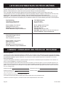
To Order Parts Under Warranty, please contact your local Empire dealer. See the dealer locator at www.empirecomfort.com. To provide
warranty service, your dealer will need your name and address, purchase date and serial number, and the nature of the problem with
thereplace.
To Order Parts After the Warranty Period, please contact your dealer or one of the Master Parts Distributors listed below. This list
changesfromtimetotime.Forthecurrentlist,pleaseclickontheMasterPartsbuttonatwww.empirecomfort.com.
PleaseNOTICE:MasterPartsDistributorsareindependentbusinessesthatstockthemostcommonlyorderedOriginalEquipment
repair parts for Heaters, Grills, and Fireplaces manufactured by Empire Comfort Systems.
MASTER PARTS DISTRIBUTOR LIST
Parts Not Under Warranty
Parts can be ordered through your Service Person, Dealer, or a Master Parts Distributor. See this page for the Master Parts Distribu-
tors list. For best results, the service person or dealer should order parts through the distributor. Parts can be shipped directly to the
service person/dealer.
Warranty Parts
Warranty parts will need a proof of purchase and can be ordered by your Service Person or Dealer. Proof of purchase is required for
warranty parts.
AllpartslistedinthePartsListhaveaPartNumber.Whenorderingparts,rstobtaintheModelNumberandSerialNumberfromthe
nameplateonyourequipment.ThendeterminethePartNumber(nottheIndexNumber)andtheDescriptionofeachpartfromthefol-
lowing illustration and part list. Be sure to give all this information . . .
FireplaceModelNumber Part Description
FireplaceSerialNumber PartNumber
TypeofGas(PropaneorNatural)
Do not order bolts, screws, washers or nuts. They are standard hardware items and can be purchased at any local hardware store.
Shipmentscontingentuponstrikes,resandallcausesbeyondourcontrol.
HOW TO ORDER REPAIR PARTS
Dey Distributing
1401WillowLakeBoulevard
VadnaisHeights,MN55101
Phone: 651-490-9191
Toll Free:800-397-1339
Website: www.deydistributing.com
Parts: Heater, Hearth and Grills
F. W. Webb Company
200 Locust Street
Hartford, CT 06114
Phone:860-722-2433
Toll Free: 800-243-9360
Fax: 860-293-0479
Toll Free Fax:800-274-2004
Websites: www.fwwebb.com & www.victormfg.com
Parts: Heater, Hearth and Grills
East Coast Energy Products
10 East Route 36
WestLongBranch,NJ07764
Phone: 732-870-8809
Toll Free:800-755-8809
Fax: 732-870-8811
Website: www.eastcoastenergy.com
Parts: Heater, Hearth and Grills

37134-6-0520 Page 19
WARRANTY
Empire Comfort Systems Inc. warranties this space heating product to be free from defects at the time of purchase and for the periods
speciedbelow.Spaceheatingproductsmustbeinstalledbyaqualiedtechnicianandmustbemaintainedandoperatedsafely,in
accordance with the instructions in the owner’s manual. This warranty applies to the original purchaser only and is not transferable. All
warrantyrepairsmustbeaccomplishedbyaqualiedgasappliancetechnician.
Limited Ten-Year Parts Warranty – Combustion Chamber
Empirepromisestotheownerthatifthecombustionchamber(seepartslist)failsbecauseofdefectiveworkmanshipor
material with ten years from the date of purchase, Empire will repair or replace at Empire’s option.
Limited One-Year Parts Warranty – Remote Controls, Accessories, and Parts
Shouldanyremotecontrol,accessory,orotherpartfailbecauseofdefectiveworkmanshipwithinoneyearfromthedateof
purchase, Empire will repair or replace at Empire’s option.
Duties Of The Owner
Theappliancemustbeinstalledbyaqualiedinstallerandoperatedinaccordancewiththeinstructionsfurnishedwiththe
appliance.Abillofsale,cancelledcheck,orpaymentrecordshouldbekepttoverifypurchasedateandestablishwarranty
period. Ready access to the appliance for service.
What Is Not Covered
Damages that might result from the use, misuse, or improper installation of this appliance.
Travel, diagnostic costs and freight charges on warranted parts to and from the factory.
Claimsthatdonotinvolvedefectiveworkmanshipormaterials.
Unauthorized service or parts replacements.
Removal and reinstallation cost.
Inoperableduetoimproperorlackofmaintenance.
How To Get Service
Tomakeaclaimunderthiswarranty,pleasehaveyourreceiptavailableandcontactyourinstallingdealer.Providethedealer
withthemodelnumber,serialnumber,typeofgas,andpurchaseverication.Theinstallingdealerisresponsibleforproviding
serviceandwillcontactthefactorytoinitiateanywarrantedpartsreplacements.Empirewillmakereplacementpartsavailable
at the factory. Shipping expenses are not covered.
If, after contacting your Empire dealer, service received has not been satisfactory, contact: Consumer Relations Department,
EmpireComfortSystemsInc.,POBox529,Belleville,Illinois62222,orsendane-mailto[email protected]with
“Consumer Relations” in the subject line.
Your Rights Under State Law
Thiswarrantygivesyourspeciclegalrights,andyoumayalsohaveotherrights,whichvaryfromstatetostate.

37134-6-0520Page 20
www.empirecomfort.com
Empire Comfort Systems Inc.
Belleville, IL
If you have a general question
aboutourproducts,pleasee-mail
usat[email protected].
If you have a service or repair
question, please contact your dealer.
La page est en cours de chargement...
La page est en cours de chargement...
La page est en cours de chargement...
La page est en cours de chargement...
La page est en cours de chargement...
La page est en cours de chargement...
La page est en cours de chargement...
La page est en cours de chargement...
La page est en cours de chargement...
La page est en cours de chargement...
La page est en cours de chargement...
La page est en cours de chargement...
La page est en cours de chargement...
La page est en cours de chargement...
La page est en cours de chargement...
La page est en cours de chargement...
La page est en cours de chargement...
La page est en cours de chargement...
La page est en cours de chargement...
La page est en cours de chargement...
La page est en cours de chargement...
La page est en cours de chargement...
La page est en cours de chargement...
La page est en cours de chargement...
-
 1
1
-
 2
2
-
 3
3
-
 4
4
-
 5
5
-
 6
6
-
 7
7
-
 8
8
-
 9
9
-
 10
10
-
 11
11
-
 12
12
-
 13
13
-
 14
14
-
 15
15
-
 16
16
-
 17
17
-
 18
18
-
 19
19
-
 20
20
-
 21
21
-
 22
22
-
 23
23
-
 24
24
-
 25
25
-
 26
26
-
 27
27
-
 28
28
-
 29
29
-
 30
30
-
 31
31
-
 32
32
-
 33
33
-
 34
34
-
 35
35
-
 36
36
-
 37
37
-
 38
38
-
 39
39
-
 40
40
-
 41
41
-
 42
42
-
 43
43
-
 44
44


Empire FAW40 Le manuel du propriétaire
- Catégorie
- Cheminées
- Taper
- Le manuel du propriétaire
- Ce manuel convient également à
dans d''autres langues
- English: Empire FAW40 Owner's manual
Documents connexes
-
Empire Heating Systems FAW-40-1IP Le manuel du propriétaire
-
-
Empire GWT-50-3 SG Installation Instructions And Owner's Manual
-
-
-
-
-
Empire Heating Systems GWT50W Le manuel du propriétaire
-
-
Autres documents
-
Empire Comfort Systems FAW-40-1IP Manuel utilisateur
-
Williams 9836 Mode d'emploi
-
Ashley Hearth Products AGDV20L Guide d'installation
-
-
-
GSW 72090 Manuel utilisateur
-
-
 Eskabe 9089848 Le manuel du propriétaire
-
Desa GCN6 Manuel utilisateur
-
