Maytag 23-11-2251N-004 Guide d'installation
- Catégorie
- Climatiseurs split-system
- Taper
- Guide d'installation

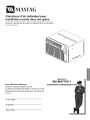
vL YFAG
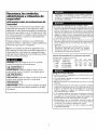
Room Air Conditioners for
Through-The-Wall Installation
Please read the operating instructions and safety precautions carefully
and thoroughly before installing and operating your air conditioner.
Keep these instructions for future reference
Questions?
866-MAYTAG-1
23-11-2251N-004

f-TABLE OF CONTENTS /
Table of Contents
Electrical Requirements and
Safety Precautions
Electrical shock hazard .................................................... 2
mportant grounding requirements ............................... 2
Additional safety precautions .......................................... 3
Installation
Before you begin ............................................................ 4
Installation Parts ............................................................. 4
nstalling the rear grille into a newwall sleeve ............ 5
nstalling the rear grille into an existing wall sleeve .... 6
nstalling the air conditioner into the sleeve .................. 9
Installing the trim frame .................................................. 9
Operation
Electronic controls ........................................................... 10
Directing airflow .............................................................. 11
Air conditioner remote control ...................................... 11
Maintenance
Cleaning the air filter .................................................... 12
Troubleshooting guide .................................................. 12
Service & Warranty
How to obtain warranty service or parts ..................... 13
Warranty .......................................................................... 13
Keep these instructions for
future reference.
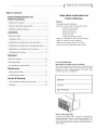
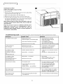
Features
• Through-the-wall installation
• Electronic controls with full-featured remote
-2 cooling & 2 fan speeds
- 24-hour on/off timer
- Energy save function
- Auto cool mode
- 1 degree temperature adjust
• Slide-out, washable air filter for easy cleaning
• Slide-out chassis for easy installation
• Exhaust vent removes stale air and odors
• Corrosion-resistant galvanized steel cabinet
For Future Reference
Write down the model and serial numbers
The model and serial numbers can be found on the
side of the cabinet near the control panel. Use these
numbers in any correspondence or service calls
concerning your air conditioner.
Model No.
Serial No.
Date of Purchase
Proof of Purchase Date
It is the responsibility of the consumer to establish the
original purchase date for warranty purposes. We
recommend that a bill of sale, cancelled check, or
some other appropriate payment record be kept for
that purpose.

INSTALLATI ON-_'_
| ELECTRICAL REQUIREMENTS |
J
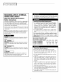
RECOGNIZE SAFETY SYMBOLS,
WORDS AND LABELS
What You Need To Know About
Safety Instructions
Warning and Important Safety Instructions appearing in
this manual are not meant to cover all possible condi-
tions and situations that may occur. Common sense,
caution and care must be exercised when operating or
cleaning tools and equipment.
Always contact your dealer, distributor, service agent or
manufacturer about problems or conditions you do not
understand.
_This is the safety alert symbol. It is used to alert you
to potential personal injury hazards. Obey all safety
messages that follow this symbol to avoid possible
injury or death.
DANGER indicates an imminently hazardous situation
which, if not avoided, will result in death or serious
injury.
WARNING indicates a potentially hazardous situation
which, if not avoided, could result in death or serious
injury.
CAUTION indicates an potentially hazardous situation
which, if not avoided, may result in minor or moderate
injury.
I CAUTION I
CAUTION used without the safety alert symbol indi-
cates a potentially hazardous situation which, if not
avoided, may result in property damage.
Do not store or use gasoline or other flammable vapors
and liquids in the vicinity of this or any other appliance.
The fumes can create a fire hazard or explosion.
Important Grounding Requirements
• Air conditioner has a three-prong grounding plug
on the power supply cord, which must be plugged
into a properly grounded three-prong wall
receptacle for your protection against possible
shock hazard. For models up to and including 7.5
amperes, use a grounding type wall receptacle to
match the cord plug.
• For models above 7.5 amperes use a single outlet
grounding type wall receptacle to match the cord
plug.
Do not operate this air conditioner without proper
time delay circuit protection (circuit breaker or fuse).
Refer to serial plate for proper power supply
requirements.
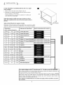
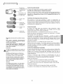
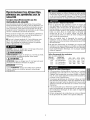
Recommended Wire Sizes
(As installed per building code) :
PROTECTORSIZEWIREGAUGE (_(_
15 AMP #14 MINIMUM
20 AMP #12 MINIMUM 125V 250V
30 AMP #10 MINIMUM 15A 20A
©©
250V 250V
15A 30A
Electrical Shock Hazard
• Plug unit only into a grounded electrical outlet.
• Do not use an extension cord or plug adapter with
this unit. Do not alter cord or plug end. Do not
remove warning label on cord.
• Do not operate unit with decorative front or filter
removed.
• If the air conditioner has a serial plate rating of 115
volts and greater than 7.5 amps, it must have its
own fuse or circuit breaker, and no other device or
unit should be operated on that fuse or circuit
breaker.
• If the air conditioner has a serial plate rating of 230
volts, it must have its own fuse or circuit breaker,
and no other device or unit should be operated on
that fuse or circuit breaker.
• We recommend that a qualified electrician install
unit in accordance with the National Electrical Code
and local codes and ordinances.
• Use copper conductors of correct wire gauge and
protector size only.

Power Cord with
Arc Detection Device
The power cord supplied with this air conditioner is
equipped with an Arc Detection Device designed to shut
off power to the unit when it senses an arc fault condition.
An arc fault is an unintentional electrical discharge that
occurs when electrical products or wires are damaged,
aged, or improperly used. An arc fault can be potentially
hazardous if left undetected.
• Do not remove or modify this plug
• Do not use as an on/off switch
• Do not use outdoors
• Do not push furniture against or place furniture on the
electrical cord. This can trip the test switch and/or
damage the cord and become a potential condition
for arcing
• Do not attempt to repair the cord. If the cord requires
replacement, call an authorized servicer.
• The Arc Detection Device is not a Ground Fault
Interrupter and should not be used as such
• The Arc Detection Device contains an electronic circuit
board and should not be submerged or exposed to
water spray
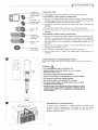
Resetti ng
If the Arc Detection Device has tripped, the reset
button will pop up.
Follow these steps to reset the Arc Detection Device:
1. Unplug unit from electrical outlet
2. Press the reset button
3. Plug the unit back into electrical outlet
4. Check to see if power has returned to the unit
Testing
You should test the Arc Detection Device equipped
power cord monthly, after every major electrical storm,
or if power to your Room Air Conditioner has been
interrupted.
Follow these steps to test the Arc Detection Device:
1. Unplug unit from electrical outlet
2. Press the reset button
3. Plug the unit back into electrical outlet
4. Presstest button. Unit should trip and reset button will
pop up.
5. Press reset button again for use
If above test fails, stop using the air conditioner and
contact customer service by calling the following toll-
free number:
1-866-629-8441
WARNING
Use two or more people to move and install air
conditioner. Failure to do so can result in back or
other injury.
CAUTION
• Do not cut, alter or remove any of the expanded
polystyrene (styrofoam) inside this air conditioner.
• Do not introduce objects in the air discharge area. This
could cause permanent damage.
• Do not pour liquids on the air conditioner asthis could
cause a malfunction. With the unit unplugged, use a
damp cloth for cleanina the unit.
CAUTION
• Do not use strong solvents to clean the air conditioner.
• Clean the air conditioner filter every two weeks to
avoid overheating caused by air obstruction. Do not
operate without filter.
• Do not obstruct the air intake area of your air
conditioner, as this could cause overheating, thus
activating the unit's security switch and shutting off the
unit.
• Do not block air circulation to outside louvers of
cabinet.
• Do not block air flow inside with blinds, curtains, or
furniture, or outside with shrubs, enclosures, or other
buildings.
• Do not run the air conditioner with an outside
protective cover in place. This could result in fire or
mechanical damage within the air conditioner.
• Carefully inspect the location where the air conditioner
will be installed. Be sure it will support the weight of
the unit over an extended period of time.

iN SY EEXYiGr',]"
Before you start
You have purchased a Through-the-Wall style air conditioner.
This type of air conditioner is designed to be installed inside
a wall sleeve mounted into a wall opening.
Tools Needed
Phillips screwdriver
Rule or tape measure
Level
You may also need a drill with 1/8" or smaller bit,
depending on your installaton requirements.
Installation Requirements
Check the location where the air conditioner will be
installed. Proper installation is your responsibility. Make
sure you have read the instructions thoroughly and have
everything necessary for correct installation.
The location should provide:
• Grounded electrical outlet within 4 ft. (122 cm) of
where the power cord exits the air conditioner.
NOTE: DO NOT USE AN EXTENSION CORD.
• Free movement of air in room to be cooled.
• A large enough opening for the air conditioner and
sleeve.
• Adequate wall support for weight of air conditioner
over an extended period of time.
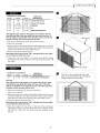
Wall Opening
Height 16"
Width: 27"
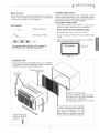
Installation Parts
Several components are included with your air conditioner
to complete a successful installation. Please compare the
contents of the carton with this illustration.
Trim frame
(4 pieces)
Through-the-wall air
conditioner
I
I
I
I
I
I
I
Wall Sleeve (sold separately)
Wall sleeve (A70052) includes front and
rear covers, plus a rear grille. Available
through your local distributor.
Sleevedimensions: 263/4"W x 15"D x 153/4"H
# 8-32 self tapping
Phillips head screws
(6 pieces)
Rear Grille: This rear grille is designed
to achieve maximum performance from
your new air conditioner. This new
grille should be installed in all wall
sleeves. Failure to install this rear grille
will void your air conditioner warranty.
4

Installing the rear grille into a
new wall sleeve:
A new wall sleeve (sold separately) will ensure the best fit
and performance of your new through-the-wall air
conditioner. See your local dealer or distributor about
purchasing wall sleeve model A70052. To locate a dealer in
your area, call 1-800-332-6658.
Follow the installation instructions that are included with
your new wall sleeve.
If you have a new wall sleeve already installed in the room
with front and rear covers in place, you may complete the
installation by attaching the rear grille.
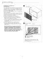
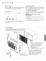
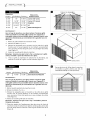
To Install the rear grille into a new wall sleeve:
1. Remove the front and back covers of the new wall
sleeve. Save the covers for future use to seal the wall
sleeve if the air conditioner is removed.
2. Clean out any debris from inside the wall sleeve, making
sure the inside is clean and that the drain holes are
completely open.
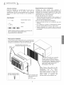
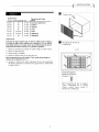
3. Insert the new grille into the wall sleeve. (Fig. 1)
4. Secure the grille to the sleeve with six (6) screws
(provided) through the holes in the grille and into the
sleeve. (Fig. 2)
Warnincj: Install the new grille that came with
your unit or new sleeve. If this rear grille is not
installed in the wall sleeve, your unit will not
operate correctly and the warranty will be void.
Both the air conditioner and the wall sleeve come
with the rear grille. Ifyou have ordered both
items, you may discardthe extra grille.
il
Wall sleeve
Rear grille
m
IE4 View from inside
of room
/
i
# 8-32 self tapping
hillips head screws
(6 pieces)
*Note: Make sure that the word "Top",
stamped into the rear grille, can be read
from inside the room.

iN SY EEXYiGr',]"
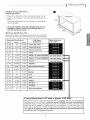
Installing the rear grille into an
existing wall sleeve:
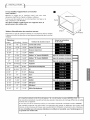
1. Measure the dimensions of your existing wall sleeve. (Fig. 3)
2. Locate your wall sleeve in the wall sleeve identification chart
below.
If you have any questions or if your sleeve is not listed please
call 217-347-6459.
You must install the new grille included with your air
conditioner. Failure to do so could damage the unit
and will void the warranty.
Wall sleeve identification chart
Determine the type of wall sleeve you have from the chart below
and follow the instructions and warnings in the section indicated.
m
T
Height
!
Width
Dimensions of wall sleeve
Wall Sleeve
Follow instructions
Width I Depth I Height
25 7/8" 18" 15 9/16"
25 3/4" 16 7/8" 18 5/8"
26 3/4" 15" 15 3/4"
26 3/4" 15" 15 3/4"
under sectionManufacturer
Carrier (52F series)
Carrier (51S Series)
Emerson Quiet Kool
Fedders
Fedders "A" chassis (BSA000D)
Fedders "B" chassis (BSB000D)
Friedrich
Frigidaire
General Electric/Hotpoint
LG
Maytag
Sears
Sears
Welbilt
Whirlpool
Whirlpool
White-Westinghouse
27" 16 314" 16 314" See note below =='
27" 19 314" 16 314" See note below ==
27" 16 3/4" 16 3/4" See note below ==
25 7/8" 16"/18"/22" 15 7/8"
26" 16 7/8" 15 5/8"
25 7/8" 16 23/32" 15 17/32"
26 3/4" 15" 15 3/4"
25 1/2" 19" 15 5/8"
25 1/2" 22 9116" 15 518"
27 318" 15 314" 18 518" See note below ==
25 1/2" 22 9/16" 15 5/8"
25 1/2" 19" 15 5/8"
25 1/2" 22" 15 1/4"
,Depth
If your existing sleeve is 27"wide or greater, STOP HERE.
These sleeves require a larger rear grille than the one provided with this unit and different
installation parts. You will need to order kit number A38500W from your local distributor.
Included in the kit is a rear grille, larger trim frame, rear air deflector, baffles, and larger foam
pieces that will be needed to correctly install your air conditioner in a wall sleeve that is 27
inches wide or greater than 27 inches. Please contact the distributor where you purchased the
unit. If you do not install your new air conditioner using this kit you will cause damage to the
air conditioner and the warranty will be void.
6

_r.,l
Dimensions of wall sleeve
Width
26 3/4"
26 3/4"
26 3/4"
25 1/2"
25 1/2"
25 1/2"
25 1/2"
Depth Height
15" 15 314"
15" 15 314"
15" 15 314"
19" 15 5/8"
22 9/16" 15 5/8"
22 9/16" 15 5/8"
19" 15 5/8"
Wall Sleeve
Manufacturer
Emerson Quiet Kool
Fedders
Maytag
Sears
Sears
Whirlpool
Whirlpool
Warning:
This type of sleeve will require you to remove the existing
rear grille and install the new grille that came with your
unit. If this new rear grille is not installed in the wall sleeve
your unit will not operate correctly and the warranty will be
void.
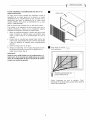
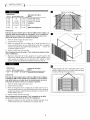
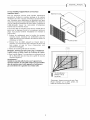
1. Remove screws attaching the existing grille to the wall sleeve.
2. Remove the existing grille.
3. Clean out any debris.
4. Insert new grille into sleeve. (Fig. 4)
Note: Make sure that the word "Top" can be read from inside
the room.(Fig. 5)
5. Secure the grille to the back of the sleeve with the six (6)
screws (provided). The screws will attach through the holes in
the grille and into the corresponding holes in the sleeve.
(Fig. 5)
IL_ Wall sleeve
Rear grille
I1_ View from inside of room
# 8-32 self tapping
Phillips head screws
(6 pieces)
Note: Make sure that the word
"Top", stamped into the rear
grille, can be read from inside
the room.

iN SY EEXYiGr',] /
Dimensions of wall sleeve
Width
25 7/8"
25 3/4"
25 7/8"
25 718"
25 1/2"
Depth Height
18" 15 9116"
16 718" 18 518"
16"118"/22" 15 718"
16 23/32" 15 17/32"
22" 15 1/4"
Wall Sleeve
Manufacturer
Carrier (52F series)
Carrier (51S Series)
Frigidaire
LG
White-Westinghouse
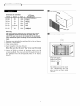
Warning:This type of sleeve will require you to remove the old
rear grille and install the new grille that came with your unit. If
this rear grille is not installed in the wall sleeve your unit will not
operate correctly and the warranty will be void.
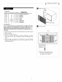
1. Remove the existing rear grille from the wall sleeve.
2. Clean out any debris.
3. Remove tabs on sides of the grille provided with your new unit by
bending tabs back and forth using a pair of pliers. Wear gloves to
protect your hands from sharp edges. (Fig. 6)
4. Insert new grille into sleeve. (Fig. 7)
Note: Make sure that the word "Top", stamped into the rear grille,
can be read from inside the room.
5. Secure the new rear grille to the sleeve by using the screws
(provided) in the same locations asthe screws that secured the old
rear grille.
m
Remove Tabs
° _°Rear grille °
Wall sleeve
Rear grille
Dimensions of wall sleeve Wall Sleeve
Width I Depth Height Manufacturer
26" I 16 7/8" 15 5/8" General Electric/Hotpoint
Warning:
This type of sleeve will require you to remove the old rear grille
and install the new grille that came with your unit. If this rear
grille is not installed in the wall sleeve your unit will not operate
correctly and the warranty will be void.
1. Remove the existing grille from the wall sleeve.
2. Clean out any debris.
3. Remove the tabs on the sides of the grille provided with your new
unit by bending the tabs back and forth using a pair of pliers.
Wear gloves to protect your hands from sharp edges. (Fig. 6)
4. Insert new grille into sleeve. (Fig. 7)
Note: Make sure that the word "Top", stamped into the rear grille,
can be read from inside the room.
5. Mark the locations of two holes on the top of the wall sleeve.
Using these marks as a guide, drill holes into the sleeve using a
1/8" drill bit. Attach the rear grille using the supplied screws.
(Fig. 8)
Ii
8

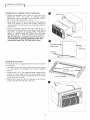
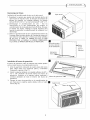
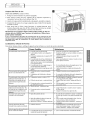
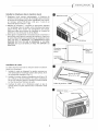
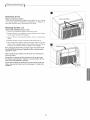
Installing the air conditioner into the wall sleeve
1. Replace any damaged foam inside the wall sleeve with
replacement foam. Two pieces of adhesive backed
replacement foam are provided, one vertical piece (15 3/4" x
3/4" x 1") and one horizontal (25" x 3/4" x 1").
2. Depending on the model, your air conditioner may weigh as
much as 95 pounds. To insure safe handling, obtain the
necessary help to lift and position the unit during installation
and removal.
3. Slide air conditioner fully into the sleeve. (Fig. 9) The air
conditioner should be centered in the sleeve so that all seals
bear evenly to prevent air leakage. NOTE: THE UNIT IS
APROX. 6" DEEPER THAN THE SLEEVE. THE UNIT WILL
PROTRUDE APROX. 6" FROM THE SLEEVE INTO THE ROOM.
When installation is complete, the unit must have a
rearward slope to prevent condensate water from
entering the room. (Fig. 10) Check with a level.
I!
m
Wall sleeve
Air conditioner
Air conditioner-_
(insideof room)
Rearward
slope
,_...Wall
sleeve
(outdoors)
Installing the trim frame
The trim frame covers any gaps between the wall sleeve and the
air conditioner.
1. Assemble trim frame by laying the 4 frame pieces face down
on a flat surface and snapping them securely together.
(Fig. 11)
2. Install the 20" x 1/2" x 1/8" adhesive backed insulating foam
around the inside edge of the trim frame. Begin in the
bottom left corner and place the insulating foam around the
entire inside of trim frame.
3. Slide the trim frame onto the air conditioner until the foam
makes a seal with the wall sleeve. (Fig. 12)
m
Wall sleeve
I
I
I
9

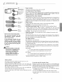
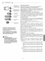
Set
Temperature/
Timer Display
Ternperature/
Timer Hour
Controls
Timer
Control
Fan Speed
Control
Mode
Control
_ Power
Control
Built-in three minute timing delay.
This electronic-controlled unit will
automatically resume operation
after a power failure.
If the electronic controls do not
respond to touch pad or remote
control commands, you must unplug
the unit from the electrical outlet
for five seconds and then plug the
unit back in.
_lb Caution:
Heat/Cool models or units with
electric heat are designed to be
used only as a supplemental
heat source. They should be
used in addition to regular
heating systems and never as
the primary source of heat.
Power Control
The Power Control turns the unit on and off.
Set Temperature/Timer Display
Shows the set temperature when the unit is in operation and hours when the
timer is being set. THE TEMPERATURE DISPLAY ONLY SHOWS THE SET
TEMPERATURE, NOT THE ACTUAL ROOM TEMPERATURE.
Temperature/Timer Hour Controls
These buttons are used to raise or lower the set temperature in increments of
1° from 66°F to 88°E By depressing both buttons at once, the display will
toggle between Celsius and Fahrenheit. When the timer is being set, these
buttons are used to change the hour setting in increments of 1 from 00 to 24.
Mode Control
A green light will
Cool Mode - The
Heat Mode (Heat
Heater Safety
indicate which mode is currently being utilized.
unit will circulate and cool the air.
Models Only)-The unit will circulate and heat the air.
Feature- When heater is powered off, low fan will
automatically stay on and run for 60 seconds to ensure the removal of
residual heat, meanwhile, the Low Fan LED blinks until the low fan stops.
Fan Mode -The unit will only circulate the air.
Energy Saver Mode - (The energy saver mode is designed to operate with
Cool mode only)
The fan will switch from the set fan speed to LO whenever the compressor
turns off in response to the thermostat. When the compressor cycles back on,
the unit will return to the original fan setting.
Fan Speed Control
High, Medium*, Low and Auto
The settings are adjusted with the Fan Speed Control, each time the button
is depressed it changes the setting. A green light will indicate which setting
is currently being used.
When the AUTO feature is selected while the air conditioner is in the COOL
or HEAT mode, the fan speeds will change automatically as the temperature
in the room changes.
COOL Mode
• 7° or more above the set temperature will use HI fan.
• 4° or less above the set temperature will use LO fan.
HEAT Mode
• 9° or more below the set temperature will use HI fan.
• 4° or less below the set temperature will use LO fan.
*MEDIUM FAN NOT available on HEAT models.
Timer Control
The timer can be set to either turn the unit on or off.
To turn the unit on using the Timer:
Depress the timer key when the power is off, the display will
read 00. Adjust to the desired number of hours before TURN
ON using the up/down arrows.
•The display will show the time by hours left until TURN ON.
•To Turn the timer off, depress the timer key.
•A green light next to the Timer Control indicates that the
timer is set.
To turn the unit OFF using the Timer:
Depress the timer key when the power is on, the display will
read 00. Adjust to the desired number of hours before TURN
OFF using the up/down arrows. The display will automatically
go back to the set temperature after 10 seconds.
•To display the amount of time left until TURN OFF, depress
the timer button once.
•To turn the TIMER OFF, depress the timer button twice.
• A green light next to the Timer Control indicates that the
timer is set.
10

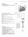
Directing Airflow
(Unit with adjustable louvers)
The unit includes adjustable louvers to direct discharge airflow.
Louvers are manually adjusted by moving the levers in the direction
of desired airflow. (Fig. 13)
Air Conditioner Remote Control
The functions on the remote control work the same as your air
conditioner's touch controls. For a full explanation of these controls
please see the previous page.
On/Off
The On/Off button is used to turn the unit on or off.
Temp/Time
The Time/Temp buttons are used to raise or lower the set
temperature. These buttons are also used to set the timer.
Mode
The Mode button changes the operational mode. Available modes
are: Fan, Cool, Heat (Heat models only), and Energy Save.
Fan Speed
Each time the button is depressed it changes the fan speed setting.
Available fan speeds are High, Low, and Auto.
Timer
The timer button accesses the timer function which can be set to
either turn the unit on or off.
CAUTION:
• Use only AAA or IEC R03 1.5V batteries.
• Remove the batteries if the remote control will not be used for
a month or longer.
• Do not attempt to recharge the supplied batteries.
• All batteries should be replaced at the same time.
• Do not dispose of the batteries in a fire as they may explode.
• Do not mix old and new batteries.
• Do not mix alkaline, standard (carbon - zinc), or rechargeable
(nickel-cadmium) batteries.
• Do not install the batteries with the polarity (+/-) reversed.
• Keep batteries and other objects that could be swallowed away
from young children. Contact a doctor immediately if an object
is swallowed.
m
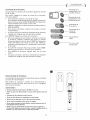
T_mer Mode
Battery replacement:
Remove the cover
on the back of the
remote control and
insert the batteries
with the (+) and (-)
poles pointing in the
proper direction.
Screwdriver required
to remove battery
cover.
11

Cleaning the air filter
EVERY TWO WEEKS: Clean the filter.
1. Turn Power OFF.
2. Remove the air filter by grasping the top corners and pulling
it up and out of the unit. (Fig. 15)
3. Wash in hot soapy water, rinse and shake dry.
4. Replace the filter with the front of the filter toward you.
5. To dry the filter thoroughly, run your unit in fan mode for a
few minutes. Remember, only a clean filter works properly
and delivers top efficiency at every setting.
Note: Failure to keep air filter clean will result in poor air
circulation. DO NOT operate without filter. This can render the
unit inoperative.
Proper use and care of your air conditioner will help ensure
longer life of the unit. It is recommended to have a
professional annually inspect and clean the coils and
condensate water passages. Expense of annual inspection is
the consumer's responsibility.
m
Decorative front
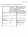
Troubleshooting Guide
Occurrence
Air conditioner will not operate
Air from unit doesnot
feel cold enough
Air conditioner cooling,
but room is too warm --
ice forming on cooling coil
tion.
behind decorative front
Air conditioner cooling,
but room too warm --
Tosavetime and expense, check the following before calling an authorized service station.
SolutionsPossible Cause
• Wall plug disconnected.
• House fuse blown or circuit breaker tripped.
• Unit turned off and then on too quickly.
• Thermostat set too low for cooling.
• Thermostat set too warm.
• Room temperature below 70°E
• Outdoortemperature below 70°E
• Dirtyair filter -- air restricted.
• Dirty air filter -- air restricted.
• Push plug firmly into wall outlet.
• Replace fuse with time delay type
or reset circuit breaker.
• If air conditioner is turned off,
wait 3 minutes before restarting.
• Adjust thermostat to higher setting for cooling.
• Set thermostat to colder temperature.
• Cooling may not occur until room
temperature rises above 70°E
• To defrost the coil set thermostat to warmer
position.
• Clean filter. See "Cleaning the Air Filter" sec-
• Cleanair filter.
Referto "CleaningAir Filter" section.
no iceforming on cooling coil
behinddecorativefront
Noise when unit is cooling
Water dripping inside
when unit is cooling
Waterdripping outside
when unit iscooling
• Thermostat set too warm.
• Air movementsound.
• Soundof fan hitting water-moisture
removalsystem.
• Window vibration -- poor installation.
• Improper installation.
• Unit removinglargequantity of moisture
from humid room.
Set thermostat to colder setting.
• Thesoundof rushingair isnormal. If too loud,
turn selectorto lower fansetting.
• Thisisnormalwhen humidity is high.
Closedoors,windows andregisters.
• Referto installation instructions--
checkwith installer.
Tilt air conditioner slightly to the outside to
allow water drainage. Refer to installation
instructions -- check with installer.
Thisisnormalduring excessivelyhumid days.
12

f ERVICE &
WARRANTY J
For Models Installed
in North America - If Service
or Parts are Required
First, make the recommended checks. If it appears that
service or parts are still required, see your room air
conditioner warranty "How to Obtain Warranty Service or
Parts".
For Models Installed
Outside North America
For room air conditioners purchased for use outside North
America, the manufacturer does not extend any warranty
either expressed or implied. Consult your local dealer for
any warranty terms extended by the importer in your
country.
How to Obtain
Warranty Service or Parts
Service for your room air conditioner will be provided by
CareCo, a division of the manufacturer with authorized
independent CareCo servicers nationwide.
Note: Before calling for service, carefully read the
Installation and Operating Instructions booklet. Then if
you need service:
1. Call a CareCo authorized servicer and advise them of
model number, serial number, date of purchase and
nature of complaint. Service will be provided during
normal working hours. Contact your dealer for the
name of an authorized servicer if unknown to you.
2. If your dealer is unable to give you the name of a
servicer or if you need other assistance, call the
following toll-free number for the name of an
authorized servicer or authorized parts distributor:
1-866-MAYTAG1
or you may write:
CareCo, Service Department
415 W. Wabash Ave., RO. Box 200
Effingham, IL 62401
Proof of Purchase Date
It is the responsibility of the consumer to establish the
original purchase date for warranty purposes. We
recommend that a bill of sale, cancelled check, or some
other appropriate payment record be kept for that
purpose.
Room Air Conditioner Warranty
(Within the 48 contiguous United States, state of Hawaii,
the District of Columbia, Puerto Rico and Canada)
Full (Five Year) Parts and Labor Warranty
During the five years after the date of original purchase, Fedders
North America will, through its authorized servicers and free of
charge to the owner or any subsequent user, repair or replace any
parts which are defective in material or workmanship due to
normal use. Ready access to the air conditioner is the
responsibility of the owner.
Note: In the event of any required parts replacement within the
period of this warranty, Fedders North America replacement parts
shall be used and will be warranted only for the period remaining
on the original warranty.
Exceptions
The above warranty does not cover failure to function caused by
damage to the unit while in your possession (other than damage
caused by defect or malfunction), or by its improper installation,
or by unreasonable use of the unit, including without limitation,
failure to provide reasonable and necessary maintenance or to
follow the written Installation and Operating Instructions. If the
unit is put to commercial, business, rental, or other use or
application other than for consumer use, we make no warranties,
express or implied, including but not limited to, any implied
warranty of merchantability or fitness for particular use or
purpose.
THE REMEDIES PROVIDED FOR IN THE ABOVE EXPRESS
WARRANTY ARE THE SOLE AND EXCLUSIVE REMEDIES THEREFOR,
NO OTHER EXPRESS WARRANTIES ARE MADE. ALL IMPLIED
WARRANTIES, INCLUDING BUT NOT LIMITED TO ANY IMPLIED
WARRANTY OF MERCHANTABILITY OR FITNESS FOR A
PARTICULAR USE OR PURPOSE, ARE LIMITED IN DURATION TO
FIVE YEARS FROM THE DATE OF ORIGINAL PURCHASE. IN NO
EVENT SHALL FEDDERS NORTH AMERICA BE LIABLE FOR
INDIRECT, INCIDENTAL, OR CONSEQUENTIAL DAMAGES, EVEN IF
ADVISED IN ADVANCE OF THE POSSIBILITY OF SUCH DAMAGES.
NO WARRANTIES, EXPRESS OR IMPLIED, ARE MADE TO ANY
BUYER UPON RESALE.
Some states do not allow limitations on how long an implied
warranty lasts or do not allow the exclusion or limitation of
incidental or consequential damages, so the above limitations or
exclusions may not apply to you. This warranty gives you specific
legal rights, and you may also have other rights which may vary
from state to state.
No warranties are made for units sold outside of the above stated
areas. Your distributor or final seller may provide a warranty on
units sold outside of these areas.
13

MAYI?AG
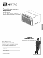
Acondicionadores de aire
empotrados
en la pared
Por favor lea las instrucciones de operaci6n y las
precauciones de seguridad cuidadosa y totalmente antes
de instalar y operar su acondicionador de aire de ventana.
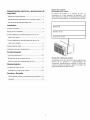
Para referencia futura
Anote los numeros de modelo y series
Encontrar_ los n0meros de modelos y series en la
mano izquierda del panel decorativo. Use estos
n0meros en cualquier correspondencia o Ilamadas
de servicio respecto a su aire acondicionado.
i Preguntas?
866-MAYTAG-1
Modelo No.
N0mero de serie
Fecha de la compra

Requerimientos electricos y precauciones de
seguridad
Riesgo de Choque El_ctrico.............................................. 2
Requerimientos Importantes para la puesta a tierra .... 2
Precauciones de seguridad adiciones .............................. 3
Instalacion
Antes de comenzar .................................................. 4
Piezas para la instalaci6n .................................................. 4
Si est_ instalando el acondicionador de aire en un
caj6n mural nuevo .......................................................... 5
Si est_ instalando el acondicionador de aire en un
aj6n mural antiguo ........................................................ 6
Desmontaje del chasis ....................................................
Instalaci6n del marco de guarnicion .....................................
Funcionamiento
Controles electronicos ...................................................... I0
Orientacion de la corriente de aire ................................ 11
Control remoto de acondicionador de aire ..... 11
Mantenimiento
Limpieza del filtro de aire .............................................. 12
Localizacion y soluci6n de averias .............................. 112
Servicio y Garantia
C6mo obtener servicio o repuestos bajo la garantia ..13
Garantia ...................................................................................
Escriba los n_meros
del modelo y de la serie
El n0mero de modelo y el n0mero de serie se
encuentran en el lado izquierdo del gabinete. Use
estos n0meros en cualquier correspondencia o Ilamada
de servicio relacionada con su acondicionador de aire.
Modelo No
NOmero de seri
Fecha de la compra
Prueba de la fecha de compra
El establecimiento de la fecha de compra original para
efectos de la garantia es responsabilidad del
consumidor. Recomendamos mantener la factura de
compra, el cheque cancelado o alg0n otto registro de
pago apropiado para dicho efecto.

Reconozca los simbolos,
advertencias y etiquetas de
seguridad
Informaci6n sobre las Instrucciones de
Seguridad
Las advertencias e instrucciones importantes sobre
seguridad que aparecen en este manual no estan
destinadas a cubrir todas las posibles circunstancias y
situaciones que puedan ocurrir. Se debe ejercer senti-
do comun, precauci0n y cuidado cuando instale, efec-
toe mantenimiento o cuando use este distribuidor
personal de bebidas.
Siempre p0ngase en contacto con su distribuidor,
agente de servicio o fabricante si surgen problemas o
situaciones que usted no comprenda.
leste es el simbolo de alerta de seguridad. Sirve
para advertir al usuario de un posible riesgo para su
integridad fisica. Siga todos los mensajes de seguri-
dad que figuren despu_s de este simbolo para evitar
lesiones o incluso la muerte.
P_ 'lx,l_lH[€'l_[o_
PELIGRO indica un riesgo el cual, si no se evita,
causara la muerte o una herida grave.
IA ADW T NC,AI
ADVERTENCIA indica un riesgo el cual, si no se
evita, puede causar la muerte o una herida grave.
I_ PRECAUCIONI
PRECAUCION indica un riesgo, el cual, si no se evita,
puede causar heridas menores o moderadas.
JPRECAUCION I
PRECAUCION cuando se usa sin el simbolo de alerta,
indica una situaci0n que podria resultar en el da_o
del equipo.
No g e ni use gaso ina u otros vapores y
inflamables en la vecindad de este o cualquier otro
artefacto. Los vapores emitidos pueden crear un riesgo
de incendio o explosi6n.
uerimientos Importantes para a Puesta a erra
El cord6n de alimentaci6n del acondicionador de air_
tiene un enchufe de tres clavijas con puesta atierra el cua
debe ser enchufado en un tomacorriente mural puesto
tierra de tres alv_olos para su protecci6n contra posibl_
riesgo de choque el_ctrico. Para los modelos de hasta 7,_E
amperes o menos, use un tomacorriente mural del tipc
con puesta a tierra que tenga la misma configuraci6n qu_
el enchufe del cord6n de alimentaci6n.
Para los modelos de mas de 7,5 amperes, use un toma-
corriente mural sencillo con puesta a tierra que tenga la
misma configuraci6n que el enchufe del cord6n de ali-
mentaci6n.
No haga funcionar este acondicionador de aire sin
protecci6n adecuada del circuito de retardo.
Consulte la placa de serie para los requerimientos
apropiados de alimentaci6n el_ctrica.
Tamafios Recomendados de los conductores del circuito
(InstaladossegOnel codigodeconstrucci6n):
©©©©
LOSFUSIBLES CONDUCTORES
15AMP #14COMOMINIMO 125V 250V 250V 250V
20AMP #12COMOMINIMO 15A 20A 15A 30A
30AMP #10COMOMINIMO
rico
Enchufe el aparato solamente en un tomacorriente el_c-
trico puesto a tierra.
Con este aparato no use un cord6n de extensi6n ni ur
adaptador de enchufe.
No haga funcionar el acondicionador de aire sin el pane
delantero.
Si el acondicionador de aire tiene una potencia nomina
indicada en la placa de serie de 115 voltiosyde mas de 7,_E
amperes, es necesario que sea protegido con su propic
fusible o disyuntor y ningOn otro dispositivo debe usar
ese mismo disyuntor o fusible.
Si el acondicionador de aire tiene una potencia nomina
en la placa de serie de 230 voltios, es necesario que see
protegido con su propio fusible o disyuntor y ningOn otrc
aparato debe usar ese mismo disyuntor o fusible.
Recomendamos que un electricista calificado instale e
acondicionador de aire de acuerdo con el c6digo el_ctri-
co nacional y los c6digos y reglamentos locales.
Use solamente conductores de cobre y fusibles de calibr_
y capacidad adecuada.

C3UERIMIENTOS ELECTRIC©S Y |
EGAUC!ONES DE SEGUR!DAD
Cordon con dispositivo de deteccion de arco
electrico
El cord6n el6ctrico proporcionado con este acondicionador
de aire viene equipado con un dispositivo de detecci6n de
arco el6ctrico dise_ado para apagar el suministro el6ctrico a
la unidad cuando detecta una condici6n de falla per arco
el6ctrico. Una falla per arco el6ctrico es una descarga el6ctri-
ca accidental cuando los artefactos o cables el6ctricos est_qn
da_ados, son antiguos o no se han usado de manera ade-
cuada. Una falla per arco el6ctrico puede ser peligrosa si no
se detecta a tiempo.
_'!_1 'll#ll[_0]
• No retire o modifique este enchufe
i o Io utilice come un interrupter de encendido/apa-
gado
No Io use en el exterior
No coloque muebles contra o sobre el cord6n electri-
co. Esto puede disparar el interrupter de prueba y/o
da_ar el cord6n, adem_is de crear una condici6n
potencial de arco electrico
No intente reparar el cord6n. Si necesita reemplazar el
cord6n, Ilame a un tecnico de servicio autorizado
El dispositivo de detecci6n de arco electrico no es un
interrupter de falla de conexi6n a tierra y no se debe
usar come tal
El dispositivo de detecci6n de arco electrico contiene
un tablero de circuitos electr6nico y no se debe
sumergir o exponer al agua
Restablecimiento
Si el dispositivo de detecci6n de arco el_ctrico se ha dis-
parade, el bot6n 'RESET' (Restablecer) se levantar_q.
Siga los siguientes pasos para restablecer el dispositivo de
detecci6n de arco el6ctrico:
1. Desenchufe la unidad del tomacorriente
2. Oprima el bot6n 'RESET' (Restablecer)
3. Enchufe la unidad nuevamente en el tomacorriente
4. Verifique que Ilega energia el6ctrica a la unidad
Pruebas
Realice pruebas del dispositivo de detecci6n de arco el_ctrico
una vez al mes, despu6s de cada tormenta el6ctrica grande, o
si se ha interrumpido el suministro el6ctrico al acondicionador
de aire de habitaci6n.
Siga los siguientes pasos para probar el dispositivo de detec-
ci6n de arco el6ctrico:
1. Desenchufe la unidad del tomacorriente
2. Oprima el bot6n 'RESET' (Restablecer)
3. Enchufe la unidad nuevamente en el tomacorriente
4. Oprima el bot6n de prueba. El dispositivo debe dispararse
y el bot6n 'RESET' (restablecer) debe levantarse.
5. Oprima el bot6n 'RESET' (Restablecer) nuevamente para
activar la unidad
Si la prueba anterior falla, deje de usar el acondicionador de
aire y p6ngase en contacto con servicio al cliente.
ADVERTENCIA
Emplee a dos o mas personas para mover e instalar el
acondicionador de aire.
PRECAUCION
No corte, modifique ni retire ningOn pedazo de polie-
stireno expandido (espuma blanca) situado dentro de
este acondicionador de aire.
No introduzca objetos en el _qrea de descarga del aire.
Esto puede causar da_o irreparable a su acondicionador
de aire.
No vierta liquidos de limpieza en el acondicionador de
aire pues esto puede causar un malfuncionamiento. Use
un pa_o hOmedo para limpiarlo.
PRECAUCION
Evite usar solventes fuertes para limpiar el acondi-
cionador de aire.
Limpie el filtro del acondicionador de aire cada dos sem-
anas para evitar sobrecalentamiento causado per obstruc-
ci6n del aire.
No obstruya el _qrea de entrada del aire de su acondi-
cionador, pues esto puede causar sobrecalentamiento, Io
cual activar_q el interrupter de seguridad y apagar_q el
aparato.
No bloquee la circulaci6n del aire hacia las rejillas de ven-
tilaci6n exteriores del gabinete.
No obstruya el flujo del aire hacia el interior con per-
sianas, cortinas o muebles o hacia el exterior con arbus-
tos, recintos u otros edificios.
No haga funcionar el acondicionador de aire teniende
instalada la cubierta protectora exterior. Esto podria
resultar en da_o mec_qnico dentro del acondicionador de
aire.
Soporte adecuado de la pared para el peso del acondi-
cionador de aire durante un periodo de tiempo prolon-
gado.

Antesdecomenzar
Usted ha comprado un acondicionador de aire para su
instalaci6n empotrado en la pared. Este tipo de
acondicionador de aire ha sido disefiado para set instalado
dentro de un caj6n mural montado en una cavidad en la
pared.
Tools Needed
................. _l
Destornillador comOn
Martillo
Nivel
Tambi_n puede necesitar un taladro con una broca de
1/8" o m_s pequefia, dependiendo de los
requerimientos de su instalacibn.
Requerimientos para la Instalacion
Verifique el lugar donde ser_i instalado el
acondicionador de aire. Usted es responsable de que la
instalaci6n sea apropiada. AsegQrese de haber leido
completamente las instrucciones y que tiene todo Io
necesario para una correcta instalaci6n.
El lugar debe disponer de Io siguiente:
• Tomacorriente el_ctrico puesto a tierra situado a 4
pies (122 cm) desde el lugar en que el cord6n el_ctrico
sale del acondicionador de aire.
NOTA: NO USE UN CORDON DE EXTENSION.
• Buena circulaci6n del aire en la habitaci6n que ser_i
enfriada.
• Una cavidad en la pared Io suficientemente grande
para el acondicionador de aire y el caj6n mural.
• Soporte adecuado de la pared para el peso del
acondicionador de aire durante un periodo de tiempo
prolongado.
Piezas para la instalacion
Se ban incluido varios componentes con su acondicionador
de aire que contribuyen al _xito de la instalaci6n. Pot favor
compare el contenido de la caja con esta ilustraci6n.
Marco de
guarnicibn
Acondicionador de aire para
instalacibn empotrado en la pared
I
I
Tornillos autorroscantes
de cabeza Phillips # 8-32
Espuma aisladora del
marco de guarnici6n
(2 piezas)
20" x 1/2" x 1/8"
I
I
I
I
I
Caj6n Mural (vendido por separado)
El caj6n mural (A70052) incluye la
cubierta delantera y trasera y ademas
una rejilla trasera. Disponible a trav_s de
su distribuidor local. Dimensiones del
caj6n mural: 263/4" Ancho x 15"
Profundidad x 153/4" Alto
Rejilla Trasera: Esta rejilla ha sido
disefiada para que obtenga un m_ximo
rendimiento de su nuevo
acondicionador de aire. Esta nueva
rejilla debe instalarse en todos los
cajones murales. Si no se instala esta
rejilla trasera la garantia del
acondicionador de aire quedar_q nula.
4

Siesta instalando el acondicionador de aire en un
cajon mural nuevo:
Un caj6n mural nuevo (vendido pot separado) le dar_ la
seguridad de un mejor ajuste en la pared y un mejor
rendimiento de su acondicionador de aire. Consulte con su
distribuidor local para la adquisici6n de un caj6n mural
modelo A70052. Para ubicar un distribuidor en su _rea,
Ilame al 1-800-332-6658.
Siga las instrucciones incluidas con su caj6n mural nuevo.
Si ya instal6 en la habitaci6n el caj6n mural nuevo con la
cubierta delantera y trasera en sus respectivos lugares,
complete la instalaci6n colocando la rejilla trasera.
1. Retire las cubiertas delantera y trasera del caj6n mural
nuevo. Conserve la cubiertas para uso posterior para
sellar el caj6n mural si el acondicionador de aire es
retirado.
2. Limpie toda la suciedad que pueda haber dentro del
caj6n mural, asegur_ndose de que el interior est_ limpio
y que los agujeros de desag0e est_n completamente
abiertos.
3. Inserte la rejilla nueva en el caj6n.
4. Asegure la rejilla (Fig. 1) en el caj6n empujando los seis
(6) tornillos (provistos) a trav_s de los agujeros de la
rejilla hacia el caj6n. (Fig. 2)
Advertencia:
Instale la nueva rejilla incluida con el acondicionador o el
cajon nuevo. Si no se instala esta rejilla trasera en el cajon
mural, el acondicionador de aire no funcionara de manera
correcta y se anulara la garantia.
il
Caj6n mural
Rejilla
[] Vista desde el interior __
de la habitaci6n .,.......
",,, /
/
Tornillos autorroscantes de
cabeza Phillips # 8-32
*Nota: Aseg0rese de que la palabra "Top",
estampada en la rejilla trasera, pueda leerse desde el
interior de la habitaci6n.
La page est en cours de chargement...
La page est en cours de chargement...
La page est en cours de chargement...
La page est en cours de chargement...
La page est en cours de chargement...
La page est en cours de chargement...
La page est en cours de chargement...
La page est en cours de chargement...
La page est en cours de chargement...
La page est en cours de chargement...
La page est en cours de chargement...
La page est en cours de chargement...
La page est en cours de chargement...
La page est en cours de chargement...
La page est en cours de chargement...
La page est en cours de chargement...
La page est en cours de chargement...
La page est en cours de chargement...
La page est en cours de chargement...
La page est en cours de chargement...
La page est en cours de chargement...
La page est en cours de chargement...
La page est en cours de chargement...
La page est en cours de chargement...
-
 1
1
-
 2
2
-
 3
3
-
 4
4
-
 5
5
-
 6
6
-
 7
7
-
 8
8
-
 9
9
-
 10
10
-
 11
11
-
 12
12
-
 13
13
-
 14
14
-
 15
15
-
 16
16
-
 17
17
-
 18
18
-
 19
19
-
 20
20
-
 21
21
-
 22
22
-
 23
23
-
 24
24
-
 25
25
-
 26
26
-
 27
27
-
 28
28
-
 29
29
-
 30
30
-
 31
31
-
 32
32
-
 33
33
-
 34
34
-
 35
35
-
 36
36
-
 37
37
-
 38
38
-
 39
39
-
 40
40
-
 41
41
-
 42
42
-
 43
43
-
 44
44


Maytag 23-11-2251N-004 Guide d'installation
- Catégorie
- Climatiseurs split-system
- Taper
- Guide d'installation
dans d''autres langues
Documents connexes
Autres documents
-
Fedders A7U08W2B Le manuel du propriétaire
-
GE AKCQ14DCH Le manuel du propriétaire
-
Heat Controller Comfort-Aire BG-81A Le manuel du propriétaire
-
Friedrich US12B10B Manuel utilisateur
-
-
Haier HTWR12XCR Le manuel du propriétaire
-
-
Kenmore 25378258890 Le manuel du propriétaire
-
Kenmore 25370124000 Le manuel du propriétaire
-