Bosch GCM18V-07S Mode d'emploi
- Catégorie
- Scies à onglet
- Taper
- Mode d'emploi

Operating / Safety Instructions
Consignes d’utilisation / de sécurité
Instrucciones de funcionamiento y seguridad
Call Toll Free for Consumer Information & Service Locations
Pour obtenir des informations et les adresses de nos centres de service après-vente, appelez ce numéro gratuit
Llame gratis para obtener información para el consumidor y ubicaciones de servicio
For English Version
See page 2 ●Version française
Voir page 51 ●Versión en español
Ver la página 100
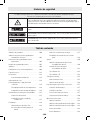
IMPORTANT
Read Before Using ●IMPORTANT
Lire avant usage ●IMPORTANTE
Leer antes de usar
1-877-BOSCH99 (1-877-267-2499) www.boschtools.com
GCM18V-07S

-2-
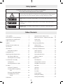
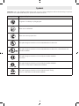
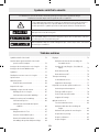
The definitions below describe the level of severity for each signal word.
Please read the manual and pay attention to these symbols.
This is the safety alert symbol. It is used to alert you to potential personal injury hazards.
Obey all safety messages that follow this symbol to avoid possible injury or death.
DANGER indicates a hazardous situation which, if not avoided, will result in death or serious
injury.
WARNING indicates a hazardous situation which, if not avoided, could result in death or
serious injury.
CAUTION indicates a hazardous situation which, if not avoided, could result in minor or
moderate injury.
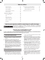
Table of Contents
Safety Symbols
Safety Symbols .................................2
General Power Tool Safety Warnings ................3
Safety Instructions for Miter Saws ..................5
Additional Safety Rules...........................7
Symbols.......................................8
Getting to Know Your Miter Saw.................. 10
Specifications ................................ 14
Intended Use................................. 14
Cutting Masonry/Metal ..................... 14
Cutting Capacities............................. 15
Unpacking and Checking Contents ............... 16
Unpacking the Miter Saw ................... 16
Checking Contents in Package ............... 16
Tools Needed For Assembly . . . . . . . . . . . . . . . . . . . . . 17
Verifying Parts ............................ 17
Checking Combination Square............... 17
Assembly.................................... 18
Storing the Torx Wrench .................... 18
Inserting and Releasing Battery
Pack ................................ 18
Removing and Installing Blades .............. 19
Assembling Dust Collection
System .............................. 20
Adjustments ................................. 22
Using the Head Assembly Lock Pin............ 22
Miter Detent System – Adjustment Procedure .. 23
0° Bevel Stop ............................. 24
45° Bevel Stop ............................ 25
Transporting and Mounting ..................... 27
Lifting the Saw............................ 27
Mounting Applications ..................... 28
Preparing for Saw Operations ................... 29
Switch Activation.......................... 29
Built-in LED Light.......................... 29
Body and Hand Position .................... 29
Workpiece Support ........................ 32
Saw Operations............................... 34
Brake Operation .......................... 34
Using the Miter Lock Knob .................. 34
Using Miter Detent System .................. 34
Chop Cuts ............................... 35
Slide Cuts................................ 36
Miter Cuts................................ 37
Bevel Cuts ............................... 38
Compound Cuts........................... 40
Cutting Base Molding ...................... 41
Cutting Crown Molding ..................... 42

-3-
General Power Tool Safety Warnings
Read all safety warnings, instructions, illustrations and specifications provided with this power
tool. Failure to follow all instructions listed below may result in electric shock, fire and/or serious injury.
SAVE ALL WARNINGS AND INSTRUCTIONS FOR FUTURE REFERENCE
The term “power tool” in the warnings refers to your mains-operated (corded) power tool or battery-operated (cordless)
power tool.
1. Work area safety
a. Keep work area clean and well lit. Cluttered or dark
areas invite accidents.
b. Do not operate power tools in explosive atmospheres,
such as in the presence of flammable liquids, gases or
dust. Power tools create sparks which may ignite the
dust or fumes.
c. Keep children and bystanders away while operating a
power tool. Distractions can cause you to lose control.
2. Electrical safety
a. Power tool plugs must match the outlet. Never modify
the plug in any way. Do not use any adapter plugs
with earthed (grounded) power tools. Unmodified
plugs and matching outlets will reduce risk of electric
shock.
b. Avoid body contact with earthed or grounded surfac-
es, such as pipes, radiators, ranges and refrigerators.
There is an increased risk of electric shock if your body is
earthed or grounded.
c. Do not expose power tools to rain or wet conditions.
Water entering a power tool will increase the risk of
electric shock.
d. Do not abuse the cord. Never use the cord for carrying,
pulling or unplugging the power tool. Keep cord away
from heat, oil, sharp edges or moving parts. Damaged
or entangled cords increase the risk of electric shock.
e. When operating a power tool outdoors, use an extension
cord suitable for outdoor use. Use of a cord suitable for
outdoor use reduces the risk of electric shock.
f. If operating a power tool in a damp location is unavoid-
able, use a Ground Fault Circuit Interrupter (GFCI)
protected supply. Use of an GFCI reduces the risk of
electric shock.
Table of Contents
Special Cuts.............................. 46
Maintenance and Lubrication.................... 47
Service .................................. 47
Batteries................................. 47
Care of Blades ............................ 47
Tool Lubrication........................... 47
Bearings................................. 47
Cleaning ................................. 47
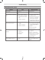
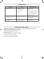
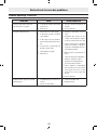
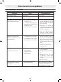
Troubleshooting .............................. 48
Troubleshooting Guide - Electrical ............ 48
Troubleshooting Guide - General ............. 49
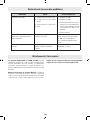
Attachments and Accessories ................... 50

-4-
General Power Tool Safety Warnings
3. Personal safety
a. Stay alert, watch what you are doing and use common
sense when operating a power tool. Do not use a
power tool while you are tired or under the influence
of drugs, alcohol or medication. A moment of inatten-
tion while operating power tools may result in serious
personal injury.
b. Use personal protective equipment. Always wear eye
protection. Protective equipment such as a dust mask,
non-skid safety shoes, hard hat, or hearing protection
used for appropriate conditions will reduce personal
injuries.
c. Prevent unintentional starting. Ensure the switch is in
the off-position before connecting to power source
and / or battery pack, picking up or carrying the tool.
Carrying power tools with your finger on the switch or
energizing power tools that have the switch on invites
accidents.
d. Remove any adjusting key or wrench before turning the
power tool on. A wrench or a key left attached to a rotat-
ing part of the power tool may result in personal injury.
e. Do not overreach. Keep proper footing and balance at
all times. This enables better control of the power tool in
unexpected situations.
f. Dress properly. Do not wear loose clothing or jewelry.
Keep your hair and clothing away from moving parts.
Loose clothes, jewelry or long hair can be caught in
moving parts.
g. If devices are provided for the connection of dust extrac-
tion and collection facilities, ensure these are connected
and properly used. Use of dust collection can reduce
dust-related hazards.
h. Do not let familiarity gained from frequent use of tools
allow you to become complacent and ignore tool safety
principles. A careless action can cause severe injury
within a fraction of a second.
4. Power tool use and care
a. Do not force the power tool. Use the correct power
tool for your application. The correct power tool will
do the job better and safer at the rate for which it was
designed.
b. Do not use the power tool if the switch does not turn
it on and off. Any power tool that cannot be controlled
with the switch is dangerous and must be repaired.
c. Disconnect the plug from the power source and/or
remove the battery pack, if detachable, from the power
tool before making any adjustments, changing acces-
sories, or storing power tools. Such preventive safety
measures reduce the risk of starting the power tool
accidentally.
d. Store idle power tools out of the reach of children and do
not allow persons unfamiliar with the power tool or these
instructions to operate the power tool. Power tools are
dangerous in the hands of untrained users.
e. Maintain power tools and accessories. Check for
misalignment or binding of moving parts, breakage
of parts and any other condition that may affect the
power tool’s operation. If damaged, have the power
tool repaired before use. Many accidents are caused by
poorly maintained power tools.
f. Keep cutting tools sharp and clean. Properly maintained
cutting tools with sharp cutting edges are less likely to
bind and are easier to control.
g. Use the power tool, accessories and tool bits etc. in
accordance with these instructions, taking into
account the working conditions and the work to be
performed. Use of the power tool for operations dif-
ferent from those intended could result in a hazardous
situation.
h. Keep handles and grasping surfaces dry, clean and free
from oil and grease. Slippery handles and grasping
surfaces do not allow for safe handling and control of the
tool in unexpected situations.

-5-
General Power Tool Safety Warnings
5. Battery tool use and care
a. Recharge only with the charger specified by the
manufacturer. A charger that is suitable for one type
of battery pack may create a risk of fire when used with
another battery pack.
b. Use power tools only with specifically designated bat-
tery packs. Use of any other battery packs may create a
risk of injury and fire.
c. When battery pack is not in use, keep it away from other
metal objects like paper clips, coins, keys, nails, screws,
or other small metal objects that can make a connec-
tion from one terminal to another. Shorting the battery
terminals together may cause burns or a fire.
d. Under abusive conditions, liquid may be ejected from
the battery, avoid contact. If contact accidentally occurs,
flush with water. If liquid contacts eyes, additionally seek
medical help. Liquid ejected from the battery may cause
irritation or burns.
e. Do not use a battery pack or tool that is damaged or
modified. Damaged or modified batteries may exhibit
unpredictable behavior resulting in fire, explosion or risk
of injury.
f. Do not expose a battery pack or tool to fire or excessive
temperature. Exposure to fire or temperature above 265
°F may cause explosion.
g. Follow all charging instructions and do not charge the
battery pack or tool outside the temperature range
specified in the instructions. Charging improperly or at
temperatures outside the specified range may damage
the battery and increase the risk of fire.
6. Service
a. Have your power tool serviced by a qualified repair
person using only identical replacement parts.
This will ensure that the safety of the power tool is
maintained.
b. Never service damaged battery packs. Service of bat-
tery packs should only be performed by the manufac-
turer or authorized service providers.
Safety Instructions for Miter Saws
a. Miter saws are intended to cut wood or wood-like
products, they cannot be used with abrasive cut-off
wheels for cutting ferrous material such as bars,
rods, studs, etc. Abrasive dust causes moving parts
such as the lower guard to jam. Sparks from abrasive
cutting will burn the lower guard, the kerf insert and
other plastic parts.
b. Use clamps to support the workpiece whenever pos-
sible. If supporting the workpiece by hand, you must
always keep your hand at least 100 mm (4”) from
either side of the saw blade. Do not use this saw to
cut pieces that are too small to be securely clamped
or held by hand. If your hand is placed too close to the
saw blade, there is an increased risk of injury from blade
contact.
c. The workpiece must be stationary and clamped or held
against both the fence and the table. Do not feed the
workpiece into the blade or cut “freehand” in any
way. Unrestrained or moving workpieces could be
thrown at high speeds, causing injury.
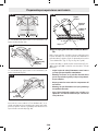
d. Push the saw through the workpiece. Do not pull the
saw through the workpiece. To make a cut, raise the
saw head and pull it out over the workpiece without
cutting, start the motor, press the saw head down and
push the saw through the workpiece. Cutting on the
pull stroke is likely to cause the saw blade to climb on top
of the workpiece and violently throw the blade assembly
towards the operator.
e. Never cross your hand over the intended line of cutting
either in front or behind the saw blade. Supporting the
workpiece “cross handed” i.e. holding the workpiece
to the right of the saw blade with your left hand or vice
versa is very dangerous.
f. Do not reach behind the fence with either hand closer
than 100 mm (4”) from either side of the saw blade,
to remove wood scraps, or for any other reason while
the blade is spinning. The proximity of the spinning saw
blade to your hand may not be obvious and you may be
seriously injured.

-6-
Safety Instructions for Miter Saws
g. Inspect your workpiece before cutting. If the work-
piece is bowed or warped, clamp it with the outside
bowed face toward the fence. Always make certain
that there is no gap between the workpiece, fence
and table along the line of the cut. Bent or warped
workpieces can twist or shift and may cause binding on
the spinning saw blade while cutting. There should be no
nails or foreign objects in the workpiece.
h. Do not use the saw until the table is clear of all tools,
wood scraps, etc., except for the workpiece. Small de-
bris or loose pieces of wood or other objects that contact
the revolving blade can be thrown with high speed.
i. Cut only one workpiece at a time. Stacked multiple work-
pieces cannot be adequately clamped or braced and may
bind on the blade or shift during cutting.
j. Ensure the miter saw is mounted or placed on a level,
firm work surface before use. A level and firm work
surface reduces the risk of the miter saw becoming
unstable.
k. Plan your work. Every time you change the bevel or
miter angle setting, make sure the adjustable fence
is set correctly to support the workpiece and will not
interfere with the blade or the guarding system. With-
out turning the tool “ON” and with no workpiece on the
table, move the saw blade through a complete simulated
cut to assure there will be no interference or danger of
cutting the fence.
l. Provide adequate support such as table extensions, saw
horses, etc. for a workpiece that is wider or longer
than the table top. Workpieces longer or wider than the
miter saw table can tip if not securely supported. If the
cut-off piece or workpiece tips, it can lift the lower guard
or be thrown by the spinning blade.
m. Do not use another person as a substitute for a table
extension or as additional support. Unstable support
for the workpiece can cause the blade to bind or the
workpiece to shift during the cutting operation pulling
you and the helper into the spinning blade.
n. The cut-off piece must not be jammed or pressed by any
means against the spinning saw blade. If confined, i.e.
using length stops, the cut-off piece could get wedged
against the blade and thrown violently.
o. Always use a clamp or a fixture designed to properly sup-
port round material such as rods or tubing. Rods have
a tendency to roll while being cut, causing the blade to
“bite” and pull the work with your hand into the blade.
p. Let the blade reach full speed before contacting the
workpiece. This will reduce the risk of the workpiece
being thrown.
q. If the workpiece or blade becomes jammed, turn the
miter saw off. Wait for all moving parts to stop and
disconnect the plug from the power source and/or re-
move the battery pack. Then work to free the jammed
material. Continued sawing with a jammed workpiece
could cause loss of control or damage to the miter saw.
r. After finishing the cut, release the switch, hold the saw
head down and wait for the blade to stop before remov-
ing the cut-off piece. Reaching with your hand near the
coasting blade is dangerous.
s. Hold the handle firmly when making an incomplete cut
or when releasing the switch before the saw head is
completely in the down position. The braking action of
the saw may cause the saw head to be suddenly pulled
downward, causing a risk of injury.
t. Avoid overheating the saw blade tips.

-7-
Additional Safety Rules
GFCI and personal protection devices like electrician’s
rubber gloves and footwear will further enhance your per-
sonal safety.
Do not use AC only rated tools with a DC power supply.
While the tool may appear to work, the electrical components
of the AC rated tool are likely to fail and create a hazard to the
operator.
Keep handles dry, clean and free from oil and grease. Slippery
hands cannot safely control the power tool.
Develop a periodic maintenance schedule for your tool.
When cleaning a tool be careful not to disassemble any
portion of the tool since internal wires may be misplaced
or pinched or safety guard return springs may be improp-
erly mounted. Certain cleaning agents such as gasoline, car-
bon tetrachloride, ammonia, etc. may damage plastic parts.
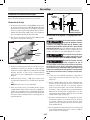
Some dust created by power sand-
ing, sawing, grinding, drilling, and
other construction activities contains chemicals known to
cause cancer, birth defects or other reproductive harm. Some
examples of these chemicals are:
• Lead from lead-based paints,
• Crystalline silica from bricks and cement and other
masonry products, and
• Arsenic and chromium from chemically-treated lumber.
Your risk from these exposures varies, depending on how of-
ten you do this type of work. To reduce your exposure to these
chemicals: work in a well ventilated area, and work with ap-
proved safety equipment, such as those dust masks that are
specially designed to filter out microscopic particles.
Do not use the Bosch GCM18V-07S
miter saw to cut fiber cement
board. Cutting materials containing crystalline silica may
create exposures to respirable silica dust.
Before each use, review all warnings
located on the miter saw.
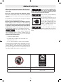
Wear Eye Protection
WARNING
The operation of any power tool can
result in foreign objects being thrown
into the eyes, which can result in se-
vere eye damage. Always wear safety
goggles that comply with ANSI Z87.1
(shown on pack age) before com-
mencing power tool operation.
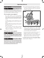
Do not use this miter saw without
properly installed base extensions.
Lack of appropriate workpiece support may result in personal
injury.
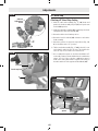
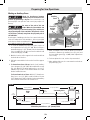
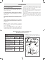
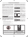
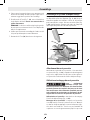
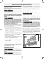
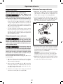
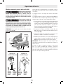
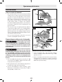
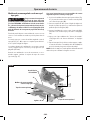
No transporte la sierra
por este mango.
Ne portez pas la scie
par cette poignée.
Do not carry the
saw by this handle.
DESIGNATED DANGER ZONES DESIGNATED NO-CARRY AREA
Avoid positioning hands, fingers or arms. A danger zone – never lift or carry saw by the main
switch handle.

-8-
Symbols
Important: Some of the following symbols may be used on your tool. Please study them and learn their meaning. Proper inter-
pretation of these symbols will allow you to operate the tool better and safer.
Symbol Designation/Explanation
V Volts (voltage)
A Amperes (current)
Hz Hertz (frequency, cycles per second)
W Watt (power)
kg Kilograms (weight)
min Minutes (time)
s Seconds (time)
CFM Cubic feet per minute [or ft3/min] (air flow rate)
⌀Diameter (size of drill bits, grinding wheels, etc.)
n0No load speed (rotational speed, at no load)
n Rated speed (Maximum attainable speed)
.../min Revolutions or reciprocation per minute (revolutions, strokes, surface speed, orbits etc. per minute)
0 Off position (zero speed, zero torque...)
1, 2, 3, ...
I, II, III, Selector settings (speed, torque or position settings. Higher number means greater speed)
Infinitely variable selector with off (speed is increasing from 0 setting)
Arrow (action in the direction of arrow)
Type or a characteristic of current
Type or a characteristic of current
Type or a characteristic of current
Designates Double Insulated Construction tools
Grounding terminal

-9-
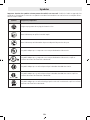
Symbols
Important: Some of the following symbols may be used on your tool. Please study them and learn their meaning. Proper inter-
pretation of these symbols will allow you to operate the tool better and safer.
Symbol Designation/Explanation
Designates Li-ion battery recycling program.
Alerts user to read manual.
Alerts user to wear eye protection.
This symbol designates that this tool is listed by Underwriters Laboratories.
This symbol designates that this tool is listed by Underwriters Laboratories, to United States and
Canadian Standards.
This symbol designates that this tool is listed by the Canadian Standards
Association.
This symbol designates that this tool is listed by the Canadian Standards
Association, to United States and Canadian Standards.
This symbol designates that this tool is listed by the Intertek Testing
Services, to United States and Canadian Standards.

-10-
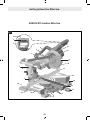
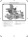
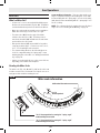
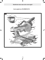
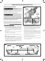
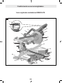
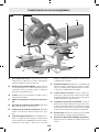
Getting to Know Your Miter Saw
GCM18V-07S Cordless Miter Saw
Fig. 1
2
3
5
6
7
8
10
12
11
10
14 15
17
18
10
11
19
20
21
22
23
4
1
16
9
13

-11-
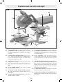
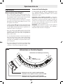
Getting to Know Your Miter Saw
1 Main Handle is used to raise and lower the head as-
sembly and contains the power switch. Pull the handle
down to lower the blade to the workpiece.
2 Switch Lock-OFF Release Buttons two buttons, one
of which must be pressed before the power switch can
be pressed.
3 Power Switch is used with the “Lock-OFF” button to
turn the saw off and on.
4 Main Carry Handle is used to carry the saw.
5 Lower Guard Link allows for smooth movement of the
lower guard.
6 Dust Chute directs sawdust up into the dust bag or
vacuum hose.
7 Bevel Post provides rotating support for all of the
miter saw parts above the table.
8 Bevel Scale and Pointers indicates the current bevel
angle. The large angled scale makes it easy to read
bevel angles.
9 Bevel Stop Indicators allow you to select the most
common bevel angles: 33.9°, 45°, or 47°.
10 Tool Mounting Pads in the four corners of the saw
provide areas to clamp, bolt, or nail the saw to a flat
work surface.
11 Stationary Fence is bolted to the base and supports
the workpiece.
12 Cast-in Carry Handles are used to lift and transport
the saw.
13 Miter Detent Plate Screws, four, accessible through
holes in the miter scale, are loosened to allow the posi-
tion of the detent plate to be adjusted.
14 Miter Detent Plate can be adjusted to set the ac-
curacy of its detent locations.
15 Miter Detents, are ten slots that allow for fast and
accurate miter cuts at common miter angles.
16 Miter Scale and Pointer allows you to see the angle
setting before a cut is made. The pointer rotates with
the table and blade and points to the angle on the miter
scale.
17 Miter Lock Knob locks the miter saw table at any
desired miter angle.
18 Miter Detent Button disengages the miter detents.
19 Table provides workpiece support, rotates for desired
miter cuts, and rotates the head assembly. The front
extended part of the table is called the miter arm.
20 Rubber Deflector is attached to the bottom of the
dust chute and deflects dust into the chute.
21 Blade is the component that makes cuts in workpiec-
es. Use only 7-1/4 (184 mm) diameter blades with
5/8” (15.88 mm) diameter arbor holes.
22 Lower Blade Guard/Lower Guard Lip helps protect
your hands from the spinning blade. It retracts as the
blade is lowered. Should the guard become jammed
on a workpiece, the lip can be used to raise the lower
guard.
23 Upper Guard covers upper part of the blade.

-12-
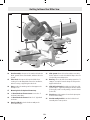
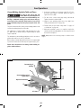
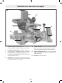
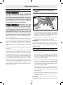
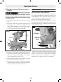
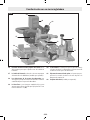
Getting to Know Your Miter Saw
24 Head Assembly is the part of the saw that includes the
blade, guards, motor, main handle, and dust collection
system.
25 Arbor Lock, when pressed, keeps the blade from
rotating. It’s used during blade removal or installation,
when loosening or tightening the arbor bolt.
26 Base provides the working surface that supports the
workpiece.sw
27 Mounting Holes for Optional Crown Stop.
28 -2° Bevel Undercut Feature Screw secures the -2°
undercut feature plate.
29 -2° Bevel Undercut Feature allows for -2° right bevel
undercuts.
30 Bevel Lock Knob locks the head assembly at the
desired bevel angle.
31 Slide System allows the head assembly to smoothly
slide in and out. It can be locked all the way to the rear
or in the fully-extended position.
32 Dust Bag collects the dust from sawing operations. To
empty it, uncouple it from the dust port and open the
zipper at the bottom.
33 Slide Rail Lock Knob when tightened, locks the slide
system in place. Tighten by turning the knob clockwise
(to the right), and loosen my turning counterclockwise
(to the left).
34 Pivot Post provides support for and is the pivot point
for the head assembly.
35 Head Assembly Lock Pin is used to lock the head
assembly in the lower position.
Fig. 2
24
25
26
10
10
13 12 27
731
34
33
32
35
8
30
28
29

-13-
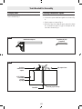
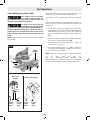
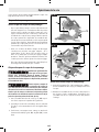
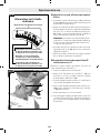
Getting to Know Your Miter Saw
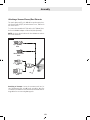
36 Battery Pack Release Button releases the battery
pack so that it can be removed from the battery bay.
37 Battery Bay is where a Bosch or AMPShare battery
pack (sold separately) is inserted.
38 Clamp Post Locations are two vertical post holes in
the base provided to support the clamp.
39 Torx Wrench is used to change the blade and to
tighten and loosen the -2° Bevel Undercut Feature
Screw (28).
40 Clamp is used to hold the workpiece to the table and
base. The clamp is inserted into one of the clamp post
locations.
41 Dust Port is the part that provides the connection to
the dust bag or vacuum hose.
42 Battery Pack (sold separately)
Fig. 3
37
36
30
42 41
38
40
33
31
38
39

-14-
Intended Use
Use this miter saw only as intend-
ed. Unintended use may result in per-
sonal injury and property damage.
This product is intended to cut wood,
wood-like products, and non-ferrous
metals. Dust build-up around the lower guard and hub from
other materials (masonry or ferrous metal) may disable the
lower guard operation.
Cutting Masonry/Metal
Do not cut ferrous metal or mason-
ry with this miter saw. The dust
from the ferrous metal or masonry cutting will cause the lower
guard to become sluggish and may not close fully and quickly
after cutting these materials.
Do not use abrasive wheels. This
tool is not intended for usage with
metal or masonry cut-off wheels.
Do not use Wet Diamond cutting
off wheel or water feed devices
with this miter saw. Masonry cutting waste will enter the
lower guard system, harden and cause the guard to become
inoperable. Use of water in masonry cutting applications with
an electric miter saw will cause electric shock hazards.
This tool is not intended for usage with metal or masonry cut-
off wheels.
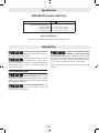
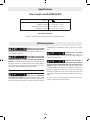
Specifications
Voltage: 18 V
Allowed ambient temperature:
– during charging
– during operation
– during storage
32…113 °F (0…+45 °C)
-4…122 °F (-20…+50 °C)
32…122 °F (0…+50 °C)
Battery Packs/Chargers
Please refer to the battery/charger list, included with your tool.
GCM18V-07S Cordless Miter Saw

-15-
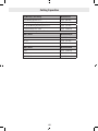
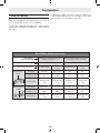
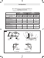
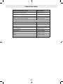
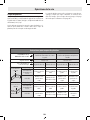
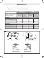
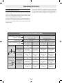
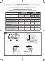
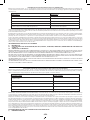
Cutting Capacities
Key Moldings / Positioning Maximum Size
Base Molding Against Fence * 3-1/2” (89 mm)
38° Crown Molding Angled Against Fence * 3-5/8” (92 mm)
45° Crown Molding Angled Against Fence * 3-3/4” (95 mm)
Crown Molding Flat on Table 8-1/4” (210 mm)
* Within miter range of 0° to 47° Left
Miter / Bevel Maximum Height
0°/ 0° 2-1/8” (54 mm)
45°/ 0° 2-1/8” (54 mm)
0°/ 45° (Left) 1-1/2” (38 mm)
Miter / Bevel Maximum Width
0°/ 0° 8-1/4” (210 mm)
45°/ 0° 5-3/4” (146 mm)
0°/ 45° (Left) 8-1/4” (210 mm)

-16-
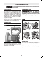
Unpacking and Checking Contents
Unpacking the Miter Saw
To avoid severe pinching, never lift
or move this saw by gripping any
component of the mechanism support system.
When removing this tool from packaging materials, reach
down to the two side carry-handle locations and slowly lift
until it clears the package.
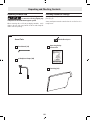
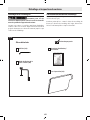
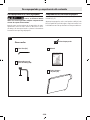
Checking Contents in Package
Open the top of the package and look for the included loose
parts (Fig. 4).
Some small parts must be attached to the tool before it is
ready for use.
Loose Parts
2 Workpiece Clamps (40)
Torx Wrench (39)
Dust Bag (32)
Operating/Safety
Instructions
Check off each part.
Fig. 4

-17-
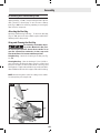
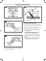
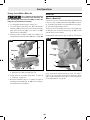
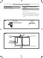
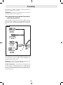
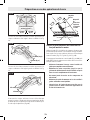
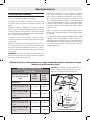
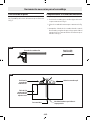
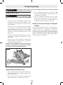
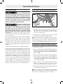
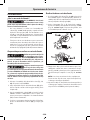
Position
combination
square.
3/4” (19mm)
board with
straight
top edge
Draw line. No gap or overlap.
Flip square here.
Fig. 6
Tools Needed For Assembly
Verifying Parts
Check that you have the tools needed for the assembly of the
saw, as shown in Fig. 5.
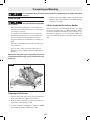
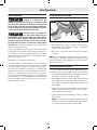
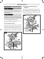
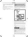
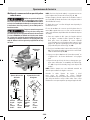
Checking Combination Square
Check that the combination square is true.
1. Position the square and draw a light line as shown in Fig.
6.
2. Flip the square as shown in Fig. 6.
3. Check the edge of the flipped square against the drawn
line, and make sure there is no gap or overlap at the bot-
tom end as shown in Fig. 6.
Fig. 5
Combination Square Torx Wrench (39)
(supplied)

-18-
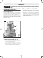
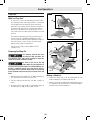
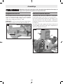
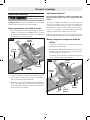
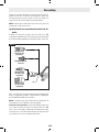
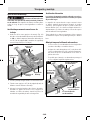
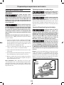
Storing the Torx Wrench
There is a storage location on the saw to store the Torx wrench
(Fig. 7, 39). Insert the short leg of the Torx wrench through
the rubber grommet as shown. Place the long leg into the tool
rest.
NOTE: The Torx wrench (39) is needed to change the blade.
If lost, use a Torx 30 wrench or a key.
Assembly
To avoid possible injury, disconnect battery pack before performing any assembly, adjustments
or repairs.
39
Fig. 7
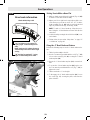
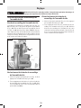
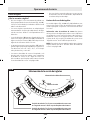
Inserting and Releasing Battery Pack
Slide charged battery pack (Fig. 8, 42) into the battery bay
(37) until the battery pack locks into position.
Your tool is equipped with a secondary locking latch to pre-
vent the battery pack from completely falling out of the bat-
tery bay, should it become loose due to vibration.
To remove the battery pack, press the battery pack release
button (36) and slide the battery pack completely out of the
battery bay.
36
37
42
35
35
Fig. 8

-19-
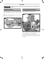
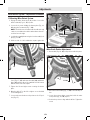
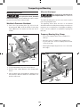
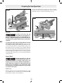
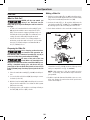
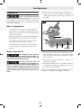
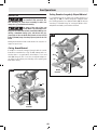
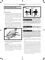
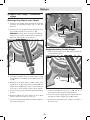
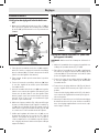
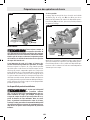
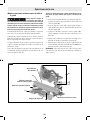
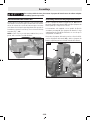
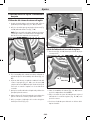
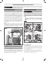
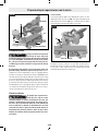
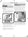
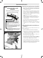
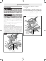
Removing and Installing Blades
Always wear gloves when changing or handling blades. Blade
tips can cause personal injury.
Removing Blade
1. Position the saw in the UP position and at 0° bevel. If in
the DOWN position: while pressing down slightly on the
saw head assembly, and pull out the head assembly lock
pin (Fig. 8, 35). Then slowly allow the saw head assembly
to come up.
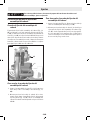
2. Rotate the Lower Blade Guard (Fig. 9, 22) until there is
clear access to the Blade Bolt.
3. Press and hold the arbor lock (the red button on the op-
posite side of the upper guard (23). Rotate the blade
(21) slowly while pressing the arbor lock until it fully
seats into its lock position.
4. Using the Torx wrench (Fig. 7, 39), loosen the blade bolt
by firmly turning it clockwise.
NOTE: This bolt has left-hand threads.
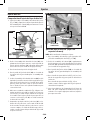
5. Remove the blade bolt and outer washer. Carefully grab
the blade. Slide the blade (Fig. 10, 21) away from the in-
ner washer and off the arbor shaft, then down and away
from the saw. Leave the inner washer on the arbor shaft.
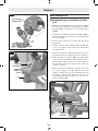
Assembly
Installing 7-1/4” (184mm) Blade
To avoid injury, do not use a blade
larger or smaller than 7-1/4”
(184mm) diameter and 5/8” (15.88 mm) arbor. The
blade’s maximum plate thickness is 5/64” (2 mm). The
blade’s maximum kerf thickness is 1/8” (3.175mm).
To reduce risk of injury, use saw
blade rated 5000/min (RPM) or
greater.
After installing a new blade, make
sure the blade does not interfere with
the table insert at 0° and 45° bevel positions. Lower the
blade into the blade slot and check for any contact with
the base or turntable structure. If the blade contacts base
or table, seek authorized service.
1. If a blade is currently installed, remove it as described in
“Removing Blade” on page 19.
2. Carefully handle the new blade. Check that the rotation
arrow on the blade matches the rotation arrow on the
upper guard. Slide the blade up and between the sides
of the chip deflector and over the arbor shaft. Move the
blade so its arbor hole goes around the support ring of
the inner washer (Fig. 9 and Fig. 10).
3. Place the outer washer over the arbor shaft and finger-
tighten the blade bolt (counterclockwise). Check that the
blade remained on the inner washer’s support ring.
4. Rotate the blade slowly while pressing the arbor lock until
it fully seats into its lock position.
5. Using the Torx wrench (Fig. 7, 39), firmly tighten the
blade bolt counterclockwise.
NOTE: This bolt has left-hand threads. Do not over tight-
en. A T30 Torx key may be used as an alternate.
6. Be sure the arbor lock is released so the blade turns
freely.
7. Place the Torx wrench (39) back in the storage area.
21
5
Blade bolt
22
23
Fig. 9
Blade
bolt
Outer
washer
21
Arbor shaft
Fig. 10

-20-
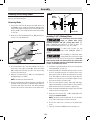
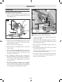
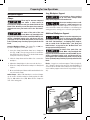
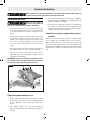
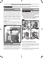
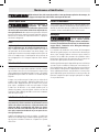
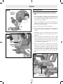
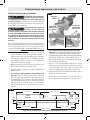
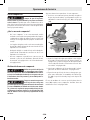
Assembling Dust Collection System
The dust collection system used on this tool is attached to the
upper guard (Fig. 11, 23). This placement provides superior
dust collection for the majority of cuts. Disconnect battery
pack (Fig. 8, 42) before attaching, adjusting or removing any
dust collection component.
Attaching the Dust Bag
Attaching and Removing Dust Bag – To attach the dust bag
(Fig. 11, 32), squeeze the two red tabs together and slide the
dust bag into the dust port rib.
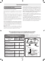
Using and Cleaning the Dust Bag
Be extremely careful when dispos-
ing of dust. Materials in fine parti-
cle form may be explosive. Do not throw sawdust on an
open fire. Spontaneous combustion, in time, may result
from the mixture of oil or water with dust particles.
Using Dust Bag – Attach the clean bag to the dust port (Fig.
11, 41).
Cleaning Dust Bag – After the dust bag is 2/3 to 3/4 full, re-
move it from the saw. Bring the bag to a proper container and
pull open the zipper located on the bottom of the bag. Hold
the bag by the coupler end and shake it vigorously until all the
dust and debris fall from it. Close zipper and reattach the bag.
NOTE: Clean the bag at the end of the cutting session and be-
fore transporting or storing the saw.
Assembly
32
23
41
17
24
Fig. 11
La page charge ...
La page charge ...
La page charge ...
La page charge ...
La page charge ...
La page charge ...
La page charge ...
La page charge ...
La page charge ...
La page charge ...
La page charge ...
La page charge ...
La page charge ...
La page charge ...
La page charge ...
La page charge ...
La page charge ...
La page charge ...
La page charge ...
La page charge ...
La page charge ...
La page charge ...
La page charge ...
La page charge ...
La page charge ...
La page charge ...
La page charge ...
La page charge ...
La page charge ...
La page charge ...
La page charge ...
La page charge ...
La page charge ...
La page charge ...
La page charge ...
La page charge ...
La page charge ...
La page charge ...
La page charge ...
La page charge ...
La page charge ...
La page charge ...
La page charge ...
La page charge ...
La page charge ...
La page charge ...
La page charge ...
La page charge ...
La page charge ...
La page charge ...
La page charge ...
La page charge ...
La page charge ...
La page charge ...
La page charge ...
La page charge ...
La page charge ...
La page charge ...
La page charge ...
La page charge ...
La page charge ...
La page charge ...
La page charge ...
La page charge ...
La page charge ...
La page charge ...
La page charge ...
La page charge ...
La page charge ...
La page charge ...
La page charge ...
La page charge ...
La page charge ...
La page charge ...
La page charge ...
La page charge ...
La page charge ...
La page charge ...
La page charge ...
La page charge ...
La page charge ...
La page charge ...
La page charge ...
La page charge ...
La page charge ...
La page charge ...
La page charge ...
La page charge ...
La page charge ...
La page charge ...
La page charge ...
La page charge ...
La page charge ...
La page charge ...
La page charge ...
La page charge ...
La page charge ...
La page charge ...
La page charge ...
La page charge ...
La page charge ...
La page charge ...
La page charge ...
La page charge ...
La page charge ...
La page charge ...
La page charge ...
La page charge ...
La page charge ...
La page charge ...
La page charge ...
La page charge ...
La page charge ...
La page charge ...
La page charge ...
La page charge ...
La page charge ...
La page charge ...
La page charge ...
La page charge ...
La page charge ...
La page charge ...
La page charge ...
La page charge ...
La page charge ...
La page charge ...
La page charge ...
La page charge ...
La page charge ...
La page charge ...
La page charge ...
La page charge ...
-
 1
1
-
 2
2
-
 3
3
-
 4
4
-
 5
5
-
 6
6
-
 7
7
-
 8
8
-
 9
9
-
 10
10
-
 11
11
-
 12
12
-
 13
13
-
 14
14
-
 15
15
-
 16
16
-
 17
17
-
 18
18
-
 19
19
-
 20
20
-
 21
21
-
 22
22
-
 23
23
-
 24
24
-
 25
25
-
 26
26
-
 27
27
-
 28
28
-
 29
29
-
 30
30
-
 31
31
-
 32
32
-
 33
33
-
 34
34
-
 35
35
-
 36
36
-
 37
37
-
 38
38
-
 39
39
-
 40
40
-
 41
41
-
 42
42
-
 43
43
-
 44
44
-
 45
45
-
 46
46
-
 47
47
-
 48
48
-
 49
49
-
 50
50
-
 51
51
-
 52
52
-
 53
53
-
 54
54
-
 55
55
-
 56
56
-
 57
57
-
 58
58
-
 59
59
-
 60
60
-
 61
61
-
 62
62
-
 63
63
-
 64
64
-
 65
65
-
 66
66
-
 67
67
-
 68
68
-
 69
69
-
 70
70
-
 71
71
-
 72
72
-
 73
73
-
 74
74
-
 75
75
-
 76
76
-
 77
77
-
 78
78
-
 79
79
-
 80
80
-
 81
81
-
 82
82
-
 83
83
-
 84
84
-
 85
85
-
 86
86
-
 87
87
-
 88
88
-
 89
89
-
 90
90
-
 91
91
-
 92
92
-
 93
93
-
 94
94
-
 95
95
-
 96
96
-
 97
97
-
 98
98
-
 99
99
-
 100
100
-
 101
101
-
 102
102
-
 103
103
-
 104
104
-
 105
105
-
 106
106
-
 107
107
-
 108
108
-
 109
109
-
 110
110
-
 111
111
-
 112
112
-
 113
113
-
 114
114
-
 115
115
-
 116
116
-
 117
117
-
 118
118
-
 119
119
-
 120
120
-
 121
121
-
 122
122
-
 123
123
-
 124
124
-
 125
125
-
 126
126
-
 127
127
-
 128
128
-
 129
129
-
 130
130
-
 131
131
-
 132
132
-
 133
133
-
 134
134
-
 135
135
-
 136
136
-
 137
137
-
 138
138
-
 139
139
-
 140
140
-
 141
141
-
 142
142
-
 143
143
-
 144
144
-
 145
145
-
 146
146
-
 147
147
-
 148
148
-
 149
149
-
 150
150
-
 151
151
-
 152
152


Bosch GCM18V-07S Mode d'emploi
- Catégorie
- Scies à onglet
- Taper
- Mode d'emploi
dans d''autres langues
Documents connexes
Autres documents
-
DeWalt DHS790AB Manuel utilisateur
-
Ryobi PBLMS01B Le manuel du propriétaire
-
-
-
-
-
Milwaukee 2739-21HD Manuel utilisateur
-
-
Milwaukee 2734-20 Manuel utilisateur
-
 Lissmac DTS 1000 Le manuel du propriétaire
