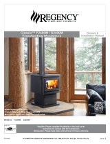
Regency Fireplace Products Classic F2400 Le manuel du propriétaire
- Catégorie
- Cheminées
- Taper
- Le manuel du propriétaire
Ce manuel convient également à

FPI FIREPLACE PRODUCTS INTERNATIONAL LTD. 6988 Venture St., Delta, BC Canada, V4G 1H4
918-154d
MODELS: F2400M S2400M
Freestanding Woodstove
11/04/14
Installer: Please complete the details on the back cover
and leave this manual with the homeowner.
Homeowner: Please keep these instructions for future reference.
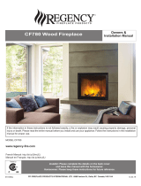
Owners &
Installation Manual
Tested by:
www.regency-re.com
French Manual: http://bit.ly/1myB2FA
F2400 Video

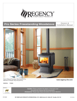
2
Regency 2400 Freestanding Woodstove
Thank-you for purchasing a
REGENCY FIREPLACE PRODUCT.
The pride of workmanship that goes into each of our products will give you years of trouble-free enjoyment. Should you
have any questions about your product that are not covered in this manual, please contact the REGENCY DEALER
in your area.
Keep those REGENCY FIRES burning.
SAFETY NOTE: If this woodstove is not properly installed, a house re may result. For your safety, follow the instal-
lation instructions, contact local building, re ofcials, or authority having jurisdiction about restrictions and installation
inspection requirements in your area.
The authority having jurisdiction should be consulted before installation to determine the need to obtain a permit.
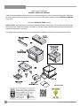
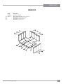
Modular Parts
F2400 Video

Regency 2400 Freestanding Woodstove
33
TABLE OF CONTENTS
Safety Label for F2400m ...............................................4
Safety Label for S2400M ...............................................5
Unit Dimensions with Classic door ................................6
Unit Dimensions with Contemporary door .....................7
Residential Installation...................................................8
Modular Installation Options ..........................................8
Room Air ....................................................................... 9
Important .......................................................................9
Minimum Clearance To Combustible Materials .............9
Stove Assembly Prior To Installation ........................... 11
Step-by-step Chimney And Connector Installation ......12
Masonry Chimney........................................................13
Masonry Fireplace .......................................................13
Factory Built Chimney .................................................13
Combustible Wall Chimney
Connector Pass-throughs ............................................ 14
Recommended Heights For Woodstove Flue ..............15
Mobile Home Installation .............................................16
Listed Components For Mobile Home Installation ....... 17
Flue Bafe & Secondary Air Tube Installation .............17
Stainless steel smoke deector ..................................18
Brick Installation ..........................................................19
Classic Door Handle .................................................... 19
Contemporary Door Handle.........................................19
Glass Installation .........................................................19
Step-by-step Optional Accessories Installation ...........19
Contemporary Door Handle.........................................19
Screen Door ................................................................20
Operating Instructions ..............................................21
Draft Control ................................................................21
First Fire ......................................................................21
Fan Operation..............................................................22
Ash Disposal................................................................22
Safety Guidelines and Warnings .................................22
Maintenance ............................................................... 23
Creosote ......................................................................23
Maintenance Of Gold-plated Doors .............................23
Latch Adjustment .........................................................23
Door Gasket ................................................................23
Glass Maintenance ...................................................... 23
Wood Storage ..............................................................23
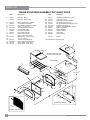
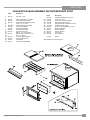
F2400m Stove Main Assembly w/classic door ............24
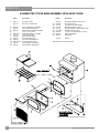
F2400m Stove Main Assembly w/contemporary door .25
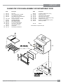
S2400m Step Stove Main Assembly w/classic door ....26
S2400m Step Stove Main Assembly w/contemporary
door .............................................................................27
Pedestal, Bottom Shield & Leg Options ......................28
Firebrick ....................................................................... 29
Warranty ......................................................................31
http://oee.nrcan.gc.ca/residential/personal/retrot-homes/retrot-qualify-grant.cfm

4
Regency 2400 Freestanding Woodstove
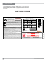
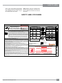
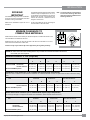
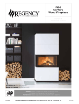
SAFETY LABEL
This is a copy of the label that accompanies each
Regency Freestanding Woodstove (F2400M).
We have printed a copy of the contents here
for your review.
NOTE: Regency units are constantly being
improved. Check the label on the unit and if
there is a difference, the label on the unit is the
correct one.
MODEL: REGENCY MEDIUM FREESTANDING STOVE - F2400M
TESTED TO: UL-1482-2011 / ULC-S627-00 / UL-737-2011 REPORT NO:219-S-02-2
THE F2400M MEETS UL737 STANDARD FOR FIREPLACE STOVES WHEN A FIRESCREEN IS PROVIDED.
MINIMUM ALCOVE CEILING HEIGHT: 2.15 M / 7 FT MAXIMUM ALCOVE DEPTH 915 MM / 36 IN.
MINIMUM CLEARANCES FOR HORIZONTAL CONNECTOR TO CEILING: 455 MM / 18"
THE SPACE BENEATH THE HEATER MUST NOT BE OBSTRUCTED. OPERATE ONLY WITH FIREBRICKS IN PLACE.
F2400M WITHOUT
AIRMATE SHIELD
F2400M WITH
AIRMATE SHIELD
K 405 mm / 16 in
L 150 mm / 6 in
M 150 mm / 6 in
FOR USE WITH SOLID WOOD FUEL ONLY. USE OF OTHER FUELS MAY DAMAGE HEATER AND CREATE A HAZARDOUS CONDITION. DO NOT OBSTRUCT COMBUSTION
AIR OPENINGS. OPERATE ONLY WITH FIREBRICKS IN PLACE. RISK OF SMOKE AND FLAME SPILLAGE, OPERAT E ONLY WITH DOORS FULLY OPEN OR FULLY CLOSED.
IF INSTALLED IN A MOBILE HOME OPERATE ONLY WITH DOORS FULLY CLOSED - OPEN FEED DOOR TO FEED FIRE ONLY. WHEN OPERAT ED WITH DOORS OPEN THE
MANUFACTURER SUPPLIED SCREEN MUST BE USED. DO NOT USE GRATE OR ELEVATE FIRE. BUILD WOOD FIRE DIRECTLY ON HEARTH. DO NOT OVERFIRE - IF HEATER
OR CHIMNEY CONNECTOR GLOWS YOU ARE OVERFIRING. INSPECT AND CLEAN CHIMNEY AND CONNECTOR FREQUENTLY. UNDER CERTAIN CONDITIONS OF USE
CREOSOTE BUILDUP MAY OCCUR RAPIDLY. KEEP FURNISHINGS AND OTHER COMBUSTIBLE MATERIAL AWAY FROM HEATER. REPLACE GLASS ONLY WITH NEOCERAM
GLASS. COMBUSTIBLE FLOOR MUST BE PROTECTED BY NON-COMBUSTIBLE MATERIAL EXTENDING BENEATH THE HEATER AND TO THE FRONT AND SIDES AS INDICATED
OR TO THE NEAREST PERMITTED COMBUSTIBLE MATERIAL.
OPTIONAL COMPONENT: FAN (846-515), ELECTRICAL RATING: VOLTS 115, 60 HZ, 2 AMPS, SCREEN DOOR (846-101)
DANGER: RISK OF ELECTRIC SHOCK. DISCONNECT POWER BEFORE SERVICING UNIT. DO NOT ROUTE POWER CORD UNDER OR IN FRONT OF APPLIANCE.
COMPONENTS REQUIRED FOR MOBILE HOME INSTALLATION: OUTSIDE AIR KIT AND ONE OF THE FOLLOWING DOUBLE WALL CONNECTOR
IN CANADA: LISTED SECURITY MODEL DP, OR OLIVER MACLEOD PRO-VENT PV DOUBLE WALLED CONNECTOR WITH LISTED CHIMNEY SYSTEM: SECURITY MODEL
S2100, ICC EXCEL 2100, SELKIRK SENTINAL CF.
IN USA: LISTED DOUBLE WA LL CONNECTORS SECURITY MODEL DP, SELKIRK MODEL DS, OLIVER MACLEOD PRO VENT PV, SIMPSON DURA
VENT MODEL DVL, GSW SUPER PIPE 6, METAL-FAB DOUBLE WA LL. CONNECTED TO ONE OF THE FOLLOWING COMPATIBLE CHIMNEY SYSTEMS
SECURITY MODEL S2100 OR MODEL ASHT, SELKIRK MODEL SSII, OLIVER M ACLEOD PRO JET 3103, SIMPSON DURA PLUS, GSW MODEL SC OR
METAL-FAB TEMP/GUARD, A MERI-TEC HS, ICC EXCEL 2100 . USE CHIMNEY COMPONENTS AS SPECIFIED IN INSTALLATION INSTRUCTIONS.
AUTEUR MINIMALE DU PLAFOND DE L’ALCÔVE : 2.15 M / 7 PL PROFONDEUR MAXIMALE DE L’ALCÔVE : 915 MM / 36 PO
DÉGAGEMENT MINIMAL DU PLAFOND POUR UN CONNECTEUR HORIZONT
AL : 455 MM / 18 PO.
L’ESPACE AU-DESSOUS DU POÊLE NE DOIT PAS ÊTRE OBSTRUÉ. UTILISER SEULEMENT AVEC LES BRIQUES RÉFRACTAIRES EN PLACE.
POUR UTILISATION AVEC BOIS SOLIDE SEULEMENT. L’UTILISATION D’AUTRES COMBUSTIBLES PEUT ENDOMMAGER LE POÊLE ET CRÉER UNE CONDITION DANGEREUSE.
NE PAS OBSTRUER LES OUVERTURES D’AIR DE COMBUSTION. UTILISER SEULEMENT AVEC LA PORTE FERMÉE – OUVRIR LA PORTE DE CHARGEMENT POUR ALIMENTER
LE FEU SEULEMENT. NE PAS UTILISER DE GRILLE À BÛCHES NI SURÉLEVER LE FEU. MONTER LE FEU DE BOIS DIRECTEMENT SUR L’ÂTRE. NE PAS SURCHAUFFER – SI
LE POÊLE OU LE CONNECTEUR DE CHEMINÉE SE MET À ROUGIR, VOUS SURCHAUFFEZ. INSPECTEZ ET NETTOYEZ FRÉQUEMMENT LA CHEMINÉE ET LE CONNECTEUREN
CERTAINES CONDITIONS D’UTILISATION, UN DÉPÔT DE CRÉOSOTE PEUT SE FORMER RAPIDEMENT. GARDEZ LES MEUBLES ET AUTRES MATÉRIAUX COMBUSTIBLES
ÉLOIGNÉS DU POÊLE. REMPLACEZ LA VITRE SEULEMENT PAR DU VERRE EN NEOCERAM. LE PLANCHER COMBUSTIBLE DOIT ÊTRE PROTÉGÉ PAR DES MATÉRIAUX NON
COMBUSTIBLES DÉPASSANT DU DESSOUS, DU DEVANT ET DES CÔTÉS DU POÊLE, TEL QU’INDIQUÉ, OU JUSQU’AU MATÉRIAU COMBUSTIBLE LE PLUS PRÈS PERMIS.
COMPOSANTS EN OPTION : VENTILATEUR (846-515), ALIMENTATION ÉLECTRIQUE : 115 VOLTS, 60 HZ, 2 AMP.
DANGER : RISQUE D’ÉLECTROCUTION. DÉCONNECTER L’ALIMENTATION ÉLECTRIQUE AVANT DE FAIRE L’ENTRETIEN DU POÊLE. NE PAS INSTALLER LE CORDON
ÉLECTRIQUE SOUS OU DEVANT L’APPAREIL.
COMPOSANTS EXIGÉS POUR INSTALLATION DANS UNE MAISON MOBILE : KIT DE PRISE D’AIR EXTÉRIEUR ET L’UN DES CONNECTEURS DE CHEMINÉE À DOUBLE PAROI
SUIVANTS :
AU CANADA : CONNECTEURS DE CHEMINÉE HOMOLOGUÉS À DOUBLE PAROI : SECURITY MODÈLE DP, OU OLIVER MACLEOD PRO-VENT PV, AVEC SYSTÈME DE CHEMINÉE
HOMOLOGUÉ : SECURITY MODÈLE S2100, ICC EXCEL 2100, SUPER VENT 2100, SUPERPRO 2100, CF SENTINAL.
AUX ÉTATS-UNIS : CONNECTEURS DE CHEMINÉE HOMOLOGUÉS À DOUBLE PAROI : SECURITY MODÈLE DP, SELKIRK MODEL DS, OLIVER MACLEOD PRO VENT PV,
SIMPSON DURA VENT MODÈLE DVL, GSW SUPER PIPE 6, METAL-FAB À DOUBLE PAROI. CONNECTÉ À L’UN DES SYSTÈMES DE CHEMINÉE COMPATIBLES SUIVANTS :
SECURITY MODÈLE S2100 OU MODÈLE ASHT, SELKIRK MODÈLE SSII, OLIVER MACLEOD PRO JET 3103, SIMPSON DURA PLUS, GSW MODÈLE SC OU METAL-FAB TEMP/
GUARD, AMERI-TECHS, ICC EXCEL 2100, SIMPSON DURA PLUS HTC. UTILISER LES COMPOSANTS DE CHEMINÉE SPÉCIFIÉS DANS LES INSTRUCTIONS D’INSTALLATION.
.
244
CERTIFIED TO COMPLY WITH JULY 1990
PARTICULATE EMISSION STANDARDS.
UNITED STATES ENVIRONMENTAL
PROTECTION AGENCY
CAUTION
HOT WHILE IN OPERATION DO NOT TOUCH. KEEP CHILDREN,
CLOTHING AND FURNITURE AWAY. CONTACT MAY CAUSE
SKIN BURNS. READ NAMEPLATE AND INSTRUCTIONS.
ATTENTION
CHAUD DURANT LE FONCTIONNEMENT. NE TOUCHEZ PAS.
ÉLOIGNEZ LES ENFANTS, LES VÊTEMENTS ET LES MEUBLES.
LE CONTACT PEUT CAUSER DES BRÛLURES DE LA PEAU.
LISEZ LA PLAQUE SIGNALÉTIQUE ET LES INSTRUCTIONS
MADE IN CANADA / FAIT AU CANADA
MANUFACTURED BY/ FABRIQUÉ PAR:
FPI FIREPLACE PRODUCTS INTERNATIONAL LTD.
6988 VENTURE ST.
DELTA, BC V4G 1H4
LISTED SPACE HEATER, SOLID FUEL TYPE, ALSO
SUITABLE FOR MOBILE HOME INSTALLATION /
APPAREIL DE CHAUFFAGE AMBIANT HOMOLOGUÉ
À COMBUSTIBLE SOLIDE, CONVENANT AUSSI
POUR INSTALLATION DANS UNE MAISON MOBILE
FLOOR PROTECTION*
PROTECTION DE PLANCHER*
*
Au Canada, la protection de plancher doit dépasser de
18 po (457 mm) à l’avant et de 8 po (200 mm) de chaque
côté du poêle et derrière le
poêle.
* In Canada, fl oor protection must extend 18" (450mm)
to the front and 8" (200mm) to each side and back of
the stove.
DO NOT REMOVE THIS LABEL/
NE RETIREZ PAS CETTE ÉTIQUETTE
244
INSTALL AND USE ONLY IN ACCORDANCE WITH THE MANUFACTURER'S INSTALLATION AND OPERATING INSTRUCTIONS.
CONTACT LOCAL BUILDING OR FIRE OFFICIALS ABOUT RESTRICTIONS AND INSTALLATION INSPECTION IN YOUR AREA.
USE 150 MM (6 IN.) DIAMETER MINIMUM 24 MSG BLACK OR 26 MSG BLUED STEEL CONNECTOR WITH LISTED UL103 HT
FACTORY-BUILT CHIMNEY SUITABLE FOR USE WITH SOLID FUELS OR MASONRY CHIMNEY.
SEE LOCAL BUILDING CODE AND MANUFACTURER'S INSTRUCTIONS FOR PRECAUTIONS REQUIRED FOR PASSING A
CHIMNEY THROUGH A COMBUSTIBLE WALL OR CEILING. DO NOT PASS CHIMNEY CONNECTOR THROUGH COMBUSTIBLE
WALL OR CEILING. DO NOT CONNECT THIS UNIT TO A CHIMNEY FLUE SERVING ANOTHER APPLIANCE.
INSTALLER ET UTILISER SEULEMENT SELON LES INSTRUCTIONS D’INSTALLATION ET D’UTILISATION DU FABRICANT.
CONTACTER LES RESPONSABLES DU BÂTIMENT OU DU SERVICE-INCENDIE DE VOTRE RÉGION POUR CONNAÎTRE
LES RESTRICTIONS ET EXIGENCES D’INSPECTION DANS VOTRE RÉGION. UTILISER UN CONNECTEUR D’UN DIAMÈTRE
MINIMAL DE 150 MM (6 PO) 24 MSG EN ACIER NOIR OU 26 MSG EN ACIER BRONZÉ AVEC CHEMINÉE PRÉFABRIQUÉE
HOMOLOGUÉE UL103 HT CONÇUE POUR UTILISATION AVEC COMBUSTIBLES SOLIDES OU UNE CHEMINÉE DE MAÇON-
NERIE.
VOIR LE CODE DU BÂTIMENT LOCAL ET LES INSTRUCTIONS DU FABRICANT CONCERNANT LES PRÉCAUTIONS
EXIGÉES POUR INSTALLER UNE CHEMINÉE TRAVERSANT UN MUR OU PLAFOND EN MATÉRIAUX COMBUSTIBLES.
NE FAITES PAS TRAVERSER LE CONNECTEUR DE CHEMINÉE DANS UN MUR OU PLAFOND EN MATÉRIAUX COMBUS-
TIBLES. NE RACCORDEZ PAS CE POÊLE À BOIS À UN CONDUIT DE CHEMINÉE DESSERVANT UN AUTRE APPAREIL.
MINIMUM CLEARANCES TO COMBUSTIBLE MATERIALS
DÉGAGEMENTS MINIMUMS AUX MATÉRIAUX COMBUSTIBLES
F2400M WITH AIRMATE SHIELD F2400M WITHOUT AIRMATE SHIELD
RESIDENTIAL INSTALLATION USING
SINGLE WALL CONNECTOR
MEASURE FLUE
FROM HEATER CENTER-LINE
RESIDENTIAL INSTALLATION USING
SINGLE WALL CONNECTOR
SIDEWALL A 457 mm / 18 in D 762 mm / 30 in
BACKWALL B 305 mm / 12 in E 470 mm / 18.5 in
CORNER C 165 mm / 6.5 in F 457 mm / 18 in
INSTALLATION USING LISTED DOUBLE WALL
CONNECTOR - MOBILE HOME
SIDEWALL A 380 mm / 15 in D 685 mm / 27 in
BACKWALL B 165 mm / 6.5 in E 330 mm / 13 in
CORNER C 152 mm / 6 in F 444 mm / 17.5in
INSTALLATION USING LISTED DOUBLE WALL
CONNECTOR - RESIDENTIAL CLOSE CLEARANCE
SIDEWALL A 380 mm / 15 in D 685 mm / 27 in
BACKWALL B 165 mm / 6.5in E 330 mm / 13 in
CORNER C 152 mm / 6 in F 444 mm / 17.5 in
INSTALLATION USING LISTED DOUBLE WALL
CONNECTOR - ALCOVE
SIDEWALL A 406 mm / 16 in D 711 mm / 28 in
BACKWALL B 280 mm / 11 in E 444 mm / 17.5 in
CORNER C 152 mm / 6 in F 444 mm / 17.5 in
INSTALLATION USING LISTED DOUBLE WALL
CONNECTOR - MOBILE HOME
SIDEWALL A 380 mm / 15 in D 685 mm / 27 in
BACKWALL B 140 mm / 5.5 in E 304 mm / 12 in
CORNER C 102 mm / 4 in F 393 mm / 15.5
in
SIDEWALL A 380 mm / 15 in D 685 mm / 27 in
BACKWALL B 140 mm / 5.5 in E 304 mm / 12 in
CORNER C 102 mm / 4 in F 393 mm / 15.5 in
INSTALLATION USING LISTED DOUBLE WALL
CONNECTOR - RESIDENTIAL CLOSE CLEARANCE
INSTALLATION USING LISTED DOUBLE WALL
CONNECTOR - ALCOVE
SIDEWALL G 380 mm / 15 in I 685 mm / 27 in
BACKWALL H 165 mm / 6.5 in J 330 mm / 13 in
MEASURE FLUE
FROM HEATER CENTER-LINE
SIDEWALL G 380 mm / 15 in I 685 mm / 27 in
BACKWALL H 140 mm / 5.5in J 304 mm / 12 in
918-172c
JAN FEB MAR APR MAY JUN JUL AUG SEPT OCT NOV DEC
DATE OF MANUFACTURE
2014 20162015
SAFETY LABEL FOR F2400M

Regency 2400 Freestanding Woodstove
5
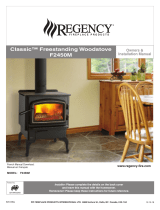
SAFETY LABEL
This is a copy of the label that accompanies
each Regency Medium Freestanding Step
Stove (S2400M). We have printed a copy of
the contents here for your review.
NOTE: Regency units are constantly being
improved. Check the label on the unit and if
there is a difference, the label on the unit is the
correct one.
SAFETY LABEL FOR S2400M
MODEL: REGENCY MEDIUM FREESTANDING STEP STOVE - S2400M
TESTED TO: UL-1482-2011 / ULC-S627-00 / UL-737-2011 REPORT NO:219-S-02-2
THE S2400M MEETS UL737 STANDARD FOR FIREPLACE STOVES WHEN A FIRESCREEN IS PROVIDED.
S2400M
K 405 mm / 16 in
L 150 mm / 6 in
M 150 mm / 6 in
MINIMUM ALCOVE CEILING HEIGHT: 2.15 M / 7 FT MAXIMUM ALCOVE DEPTH 915 MM / 36 IN.
MINIMUM CLEARANCES FOR HORIZONTAL CONNECTOR TO CEILING: 455 MM / 18"
THE SPACE BENEATH THE HEATER MUST NOT BE OBSTRUCTED. OPERATE ONLY WITH FIREBRICKS IN PLACE.
FOR USE WITH SOLID WOOD FUEL ONLY. USE OF OTHER FUELS MAY DAMAGE HEATER AND CREATE A HAZARDOUS CONDITION. DO NOT OBSTRUCT COMBUSTION
AIR OPENINGS. OPERATE ONLY WITH FIREBRICKS IN PLACE. RISK OF SMOKE AND FLAME SPILLAGE, OPERATE ONLY WITH DOORS FULLY OPEN OR FULLY CLOSED.
IF INSTALLED IN A MOBILE HOME OPERATE ONLY WITH DOORS FULLY CLOSED - OPEN FEED DOOR TO FEED FIRE ONLY. WHEN OPERATED WITH DOORS OPEN THE
MANUFACTURER SUPPLIED SCREEN MUST BE USED. DO NOT USE GRATE OR ELEVAT E FIRE. BUILD WOOD FIRE DIRECTLY ON HEARTH. DO NOT OVERFIRE - IF HEATER
OR CHIMNEY CONNECTOR GLOWS YOU ARE OVERFIRING. INSPECT AND CLEAN CHIMNEY AND CONNECTOR FREQUENTLY. UNDER CERTAIN CONDITIONS OF USE
CREOSOTE BUILDUP MAY OCCUR RAPIDLY. KEEP FURNISHINGS AND OTHER COMBUSTIBLE MATERIAL AWAY FROM HEATER. REPLACE GLASS ONLY WITH NEOCERAM
GLASS. COMBUSTIBLE FLOOR MUST BE PROTECTED BY NON-COMBUSTIBLE MATERIAL EXTENDING BENEATH THE HEATER AND TO THE FRONT AND SIDES AS INDICATED
OR TO THE NEAREST PERMITTED COMBUSTIBLE MATERIAL.
OPTIONAL COMPONENT: FAN (846-515), ELECTRICAL RATING: VOLTS 115, 60 HZ, 2 AMPS, SCREEN DOOR (846-101)
DANGER: RISK OF ELECTRIC SHOCK. DISCONNECT POWER BEFORE SERVICING UNIT. DO NOT ROUTE POWER CORD UNDER OR IN FRONT OF APPLIANCE.
COMPONENTS REQUIRED FOR MOBILE HOME INSTALLATION: OUTSIDE AIR KIT AND ONE OF THE FOLLOWING DOUBLE WALL CONNECTOR
IN CANADA: LISTED SECURITY MODEL DP, OR OLIVER MACLEOD PRO-VENT PV DOUBLE WALLED CONNECTOR WITH LISTED CHIMNEY SYSTEM: SECURITY MODEL
S2100, ICC EXCEL 2100, SELKIRK SENTINAL CF.
IN USA: LISTED DOUBLE WALL CONNECTORS SECURITY MODEL DP, SELKIRK MODEL DS, OLIVER MACLEOD PRO VENT PV, SIMPSON DURA
VENT MODEL DVL, GSW SUPER PIPE 6, METAL-FAB DOUBLE WALL. CONNECTED TO ONE OF THE FOLLOWING COMPATIBLE CHIMNEY SYSTEMS
SECURITY MODEL S2100 OR MODEL ASHT, SELKIRK MODEL SSII, OLIVER MACLEOD PRO JET 3103, SIMPSON DURA PLUS, GSW MODEL SC OR
METAL-FAB TEMP/GUARD, AMERI-TEC HS, I CC EXCEL 2100 . USE CHIMNEY COMPONENTS AS SPECIFIED IN INSTALLATION INSTRUCTIONS.
AUTEUR MINIMALE DU PLAFOND DE L’ALCÔVE : 2.15 M / 7 PL PROFONDEUR MAXIMALE DE L’ALCÔVE : 915 MM / 36 PO
DÉGAGEMENT MINIMAL DU PLAFOND POUR UN CONNECTEUR HORIZONTAL : 455 MM / 18 PO.
L’ESPACE AU-DESSOUS DU POÊLE NE DOIT
PAS ÊTRE OBSTRUÉ. UTILISER SEULEMENT AVEC LES BRIQUES RÉFRACTAIRES EN PLACE.
POUR UTILISATION AVEC BOIS SOLIDE SEULEMENT. L’UTILISATION D’AUTRES COMBUSTIBLES PEUT ENDOMMAGER LE POÊLE ET CRÉER UNE CONDITION DANGEREUSE.
NE PAS OBSTRUER LES OUVERTURES D’AIR DE COMBUSTION. UTILISER SEULEMENT AVEC LA PORTE FERMÉE – OUVRIR LA PORTE DE CHARGEMENT POUR ALIMENTER
LE FEU SEULEMENT. NE PAS UTILISER DE GRILLE À BÛCHES NI SURÉLEVER LE FEU. MONTER LE FEU DE BOIS DIRECTEMENT SUR L’ÂTRE. NE PAS SURCHAUFFER – SI
LE POÊLE OU LE CONNECTEUR DE CHEMINÉE SE MET À ROUGIR, VOUS SURCHAUFFEZ. INSPECTEZ ET NETTOYEZ FRÉQUEMMENT LA CHEMINÉE ET LE CONNECTEUREN
CERTAINES CONDITIONS D’UTILISATION, UN DÉPÔT DE CRÉOSOTE PEUT SE FORMER RAPIDEMENT. GARDEZ LES MEUBLES ET AUTRES MATÉRIAUX COMBUSTIBLES
ÉLOIGNÉS DU POÊLE. REMPLACEZ LA VITRE SEULEMENT PAR DU VERRE EN NEOCERAM. LE PLANCHER COMBUSTIBLE DOIT ÊTRE PROTÉGÉ PAR DES MATÉRIAUX NON
COMBUSTIBLES DÉPASSANT DU DESSOUS, DU DEVANT ET DES CÔTÉS DU POÊLE, TEL QU’INDIQUÉ, OU JUSQU’AU MATÉRIAU COMBUSTIBLE LE PLUS PRÈS PERMIS.
COMPOSANTS EN OPTION : VENTILATEUR (846-515), ALIMENTATION ÉLECTRIQUE : 115 VOLTS, 60 HZ, 2 AMP.
DANGER : RISQUE D’ÉLECTROCUTION. DÉCONNECTER L’ALIMENTATION ÉLECTRIQUE AVANT DE FAIRE L’ENTRETIEN DU POÊLE. NE PA S INSTALLER LE CORDON
ÉLECTRIQUE SOUS OU DEVANT L’APPAREIL.
COMPOSANTS EXIGÉS POUR INSTALLATION DANS UNE MAISON MOBILE : KIT DE PRISE D’AIR EXTÉRIEUR ET L’UN DES CONNECTEURS DE CHEMINÉE À DOUBLE PAROI
SUIVANTS :
AU CANADA : CONNECTEURS DE CHEMINÉE HOMOLOGUÉS À DOUBLE PAROI : SECURITY MODÈLE DP, OU OLIVER MACLEOD PRO-VENT PV, AVEC SYSTÈME DE CHEMINÉE
HOMOLOGUÉ : SECURITY MODÈLE S2100, ICC EXCEL 2100, SUPER VENT 2100, SUPERPRO 2100, CF SENTINAL.
AUX ÉTATS-UNIS : CONNECTEURS DE CHEMINÉE HOMOLOGUÉS À DOUBLE PAROI : SECURITY MODÈLE DP, SELKIRK MODEL DS, OLIVER MACLEOD PRO VENT PV,
SIMPSON DURA VENT MODÈLE DVL, GSW SUPER PIPE 6, METAL-FAB À DOUBLE PAROI. CONNECTÉ À L’UN DES SYSTÈMES DE CHEMINÉE COMPATIBLES SUIVANTS :
SECURITY MODÈLE S2100 OU MODÈLE ASHT, SELKIRK MODÈLE SSII, OLIVER MACLEOD PRO JET 3103, SIMPSON DURA PLUS, GSW MODÈLE SC OU METAL-FAB TEMP/
GUARD, AMERI-TECHS, ICC EXCEL 2100, SIMPSON DURA PLUS HTC. UTILISER LES COMPOSANTS DE CHEMINÉE SPÉCIFIÉS DANS LES INSTRUCTIONS D’INSTALLATION.
.
245
CERTIFIED TO COMPLY WITH JULY 1990
PARTICULATE EMISSION STANDARDS.
UNITED STATES ENVIRONMENTAL
PROTECTION AGENCY
CAUTION
HOT WHILE IN OPERATION DO NOT TOUCH. KEEP CHILDREN,
CLOTHING AND FURNITURE AWAY. CONTACT MAY CAUSE
SKIN BURNS. READ NAMEPLATE AND INSTRUCTIONS.
ATTENTION
CHAUD DURANT LE FONCTIONNEMENT. NE TOUCHEZ PAS.
ÉLOIGNEZ LES ENFANTS, LES VÊTEMENTS ET LES MEUBLES.
LE CONTACT PEUT CAUSER DES BRÛLURES DE LA PEAU.
LISEZ LA PLAQUE SIGNALÉTIQUE ET LES INSTRUCTIONS
MADE IN CANADA / FAIT AU CANADA
MANUFACTURED BY/ FABRIQUÉ PAR:
FPI FIREPLACE PRODUCTS INTERNATIONAL LTD.
6988 VENTURE ST.
DELTA, BC V4G 1H4
LISTED SPACE HEATER, SOLID FUEL TYPE, ALSO
SUITABLE FOR MOBILE HOME INSTALLATION /
APPAREIL DE CHAUFFAGE AMBIANT HOMOLOGUÉ
À COMBUSTIBLE SOLIDE, CONVENANT AUSSI
POUR INSTALLATION DANS UNE MAISON MOBILE
FLOOR PROTECTION*
PROTECTION DE PLANCHER*
* In Canada, fl oor protection must extend 18" (450mm)
to the front and 8" (200mm) to each side and back of
the stove.
DO NOT REMOVE THIS LABEL/
NE RETIREZ PAS CETTE ÉTIQUETTE
245
INSTALL AND USE ONLY IN ACCORDANCE WITH THE MANUFACTURER'S INSTALLATION AND OPERATING INSTRUCTIONS.
CONTACT LOCAL BUILDING OR FIRE OFFICIALS ABOUT RESTRICTIONS AND INSTALLATION INSPECTION IN YOUR AREA.
USE 150 MM (6 IN.) DIAMETER MINIMUM 24 MSG BLACK OR 26 MSG BLUED STEEL CONNECTOR WITH LISTED UL103 HT
FACTORY-BUILT CHIMNEY SUITABLE FOR USE WITH SOLID FUELS OR MASONRY CHIMNEY.
SEE LOCAL BUILDING CODE AND MANUFACTURER'S INSTRUCTIONS FOR PRECAUTIONS REQUIRED FOR PASSING A
CHIMNEY THROUGH A COMBUSTIBLE WALL OR CEILING. DO NOT PASS CHIMNEY CONNECTOR THROUGH COMBUSTIBLE
WALL OR CEILING. DO NOT CONNECT THIS UNIT TO A CHIMNEY FLUE SERVING ANOTHER APPLIANCE.
INSTALLER ET UTILISER SEULEMENT SELON LES INSTRUCTIONS D’INSTALLATION ET D’UTILISATION DU FABRICANT.
CONTACTER LES RESPONSABLES DU BÂTIMENT OU DU SERVICE-INCENDIE DE VOTRE RÉGION POUR CONNAÎTRE
LES RESTRICTIONS ET EXIGENCES D’INSPECTION DANS VOTRE RÉGION. UTILISER UN CONNECTEUR D’UN DIAMÈTRE
MINIMAL DE 150 MM (6 PO) 24 MSG EN ACIER NOIR OU 26 MSG EN ACIER BRONZÉ AVEC CHEMINÉE PRÉFABRIQUÉE
HOMOLOGUÉE UL103 HT CONÇUE POUR UTILISATION AVEC COMBUSTIBLES SOLIDES OU UNE CHEMINÉE DE MAÇON-
NERIE.
VOIR LE CODE DU BÂTIMENT LOCAL ET LES INSTRUCTIONS DU FABRICANT CONCERNANT LES PRÉCAUTIONS
EXIGÉES POUR INSTALLER UNE CHEMINÉE TRAVERSANT UN MUR OU PLAFOND EN MATÉRIAUX COMBUSTIBLES.
NE FAITES PAS TRAVERSER LE CONNECTEUR DE CHEMINÉE DANS UN MUR OU PLAFOND EN MATÉRIAUX COMBUS-
TIBLES. NE RACCORDEZ PAS CE POÊLE À BOIS À UN CONDUIT DE CHEMINÉE DESSERVANT UN AUTRE APPAREIL.
918-203e
JAN FEB MAR APR MAY JUN JUL AUG SEPT OCT NOV DEC
DATE OF MANUFACTURE
2014 20162015
S2400M MINIMUM CLEARANCES
TO COMBUSTIBLE MATERIALS
RESIDENTIAL INSTALLATION USING
SINGLE WALL CONNECTOR
INSTALLATION USING LISTED DOUBLE WALL
CONNECTOR - ALCOVE
SIDEWALL A 406 mm / 16 in D 711 mm / 28 in
BACKWALL B 280 mm / 11 in E 444 mm / 17.5 in
CORNER C 152 mm / 6 in F 483 mm / 19 in
INSTALLATION USING LISTED DOUBLE WALL
CONNECTOR - MOBILE HOME
SIDEWALL A 380 mm / 15 in D 685 mm / 27 in
BACKWALL B 140 mm / 5.5 in E 304 mm / 12 in
CORNER C 102 mm / 4 in F 432 mm / 17 in
SIDEWALL A 380 mm / 15 in D 685 mm / 27 in
BACKWALL B 140 mm / 5.5 in E 304 mm / 12 in
CORNER C 102 mm / 4 in F 432 mm / 17 in
INSTALLATION USING LISTED DOUBLE WALL
CONNECTOR - RESIDENTIAL CLOSE CLEARANCE
MEASURE FLUE
FROM HEATER CENTER-LINE
SIDEWALL G 380 mm / 15 in I 685 mm / 27 in
BACKWALL H 140 mm / 5.5in J 304 mm / 12 in
DÉGAGEMENTS MINIMUMS AUX
MATÉRIAUX COMBUSTIBLES
INSTALLATION RÉSIDENTIELLE UTILISANT
UN CONNECTEUR À SIMPLE PAROI
MUR LATÉRAL
MUR ARRIÈRE
COIN
MUR LATÉRAL
MUR ARRIÈRE
COIN
MUR LATÉRAL
MUR ARRIÈRE
COIN
MUR LATÉRAL
MUR ARRIÈRE
A 406mm/16po
B 280mm/11po
C
152mm/6po
A 380mm/15po
B 140mm/5.5po
C
102mm/4po
A 380mm/15po
B 140mm/5.5po
C
102mm/4po
G 380mm/15po
H 140mm/5.5po
D 711mm/28po
E 444mm/17.5po
F
483mm/19po
D 685mm/27po
E 304mm/12po
F
432mm/17po
D 685mm/27po
E 304mm/12po
F
432mm/17po
I 685mm/27po
J 304mm/12po
INSTALLATION UTILISANT UN CONNECTEUR
HOMOLOGUÉ À DOUBLE PAROI - ALCÔVE
INSTALLATION UTILISANT UN CONNECTEUR
HOMOLOGUÉ À DOUBLE PAROI - MAISON MOBILE
INSTALLATION UTILISANT UN CONNECTEUR HOMOLOGUÉ
À DOUBLE PAROI - RÉSIDENTIELLE (DÉGAGEMENT
RÉDUIT
)
MESURER DU CENTRE DU
A PARTIR DU POÊLE CONDUIT DE FUMÉE
*
Au Canada, la protection de plancher doit dépasser de
18 po (457 mm) à l’avant et de 8 po (200 mm) de chaque
côté du poêle et derrière le poêle.

6
Regency 2400 Freestanding Woodstove
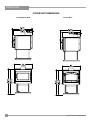
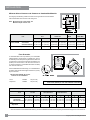
DIMENSIONS
F2400M UNIT DIMENSIONS
Classic Door
Contemporary Door

Regency 2400 Freestanding Woodstove
7
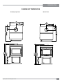
DIMENSIONS
S2400M UNIT DIMENSIONS
Classic Door
Contemporary Door

8
Regency 2400 Freestanding Woodstove
INSTALLATION
RESIDENTIAL
INSTALLATION
1) Please read this entire manual before you
install and use your new woodstove. Failure
to follow instructions may result in property
damage, bodily injury or even death. Be aware
that local Codes and Regulations may override
some items in this manual. Check with your
local inspector.
2) Select a position for your Regency Stove.
Consult the minimum clearance chart for your
model and set the stove in place. For close
clearance installation use listed double wall
connector systems.
3) To insure vertical alignment, suspend a plumb
bob from the ceiling over the exact center of
your stove ue and mark a spot on the ceiling
to indicate the center of the chimney.
4) Check that the area above the ceiling is clear
for cutting. Re-conrm the clearance from the
stove to combustibles to insure that they are
within the prescribed limits.
5) This woodstove must be connected to a UL
103 HT (ULC S629) listed chimney or a code
approved masonry chimney with a ue liner.
6) Install chimney according to chimney manu-
facturers instructions. The performance of your
woodstove is governed to a very large part by
the chimney system. Too short a chimney can
cause difcult start-up, dirty glass, back smoking
when door is open, and
even reduced heat output. Too tall a chimney
may prompt excessive draft which can result
in very short burn times and excessive heat
output. The use of an inexpensive ue pipe
damper may be helpful in reducing excessive
draft.
CAUTION: The chimney should be the same
size as the 6" ue outlet on the stove. The
chimney must be listed as suitable for use
with solid fuels. For other types of chimneys
check with your local building code ofcials.
Do not confuse a chimney with a type “B”
Venting System used for gas appliances
as suitable for a wood burning appliance.
For Mobile Home installations refer to that
section within this manual.
7) Mark the location of the pedestal base or
legs on the oor, then move the stove aside
and mark the position of the oor protector.
8) The oor protector must be of non-combus-
tible material and must extend 16" (406mm)
in front of the door opening and 6" (152mm)
to the sides and rear of the unit. Some areas
may require a larger size oor protector.
See your local inspector. For outside air
installation refer to Mobile Home installation
instructions within this manual.
9) When the oor protection is complete, posi-
tion the stove with the ue collar centered
under the installed chimney.
10) In seismically active areas, Regency rec-
ommends that your unit is secured to the
oor by using the bolt down holes inside
the pedestal (the same ones used in Mobile
Home installations).
11) For residential installations using 6" "C"
Vent (single wall) the chimney connector
must be at least 24 gauge steel. Do not use
galvanized pipe. For Mobile Home instal-
lation refer to the Mobile Home installation
instructions within this manual.
12) Do not connect this unit to a chimney
serving another appliance.
13) A chimney connector cannot pass through
an attic or roof space, closet or similar
concealed space, or a oor, ceiling, wall
or partition of combustible construction.
In Canada, if passage through a wall, or
partition of combustible construction is
desired, the installation shall conform to
CAN/CSA-B365, Installation Code for Solid-
Fuel-Burning Appliances and Equipment.
14) Your Regency Woodstove is not to be con-
nected to any air distribution duct.
Emissions from burning wood or gas could
contain chemicals known to the State of
California to cause cancer, birth defects
or other reproductive harm.
NOTE: In Canada, oor protection must
extend 18" (450mm) to the front and
8" (200mm) to each side and back
of the stove.
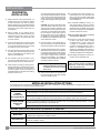
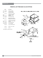
MODULAR INSTALLATION OPTIONS
Modular Part
Things to consider when choosing options:
Modular Option
Blower/Fan
Ash Drawer Kit
Screen Door
OPTIONS: These can be installed at time of installation or added later:
F2400M
Airmate OR
Rear Heat Deector
F2400M, S2400M
Pedestal OR
Legs
Things to consider when choosing options
The following items are required when assembling your Regency Stove. F2400M unit - the Rear Heat Deector is supplied with the stove, but if
you choose not to use it you must use the Airmate instead.
Clearances are different. See the Minimum Clearance to Combustible Materials chart in the Installation section of this
manual. Generally you can get closer clearances with the airmate than with the rear heat deector.
Convection heat with Airmate vs. Radiant Heat with Rear Heat Deector. The airmate pushes heat forward and into the
room, the rear heat deector deects the heat upward. Refer to the Installation section within this manual.
There are no performance differences with either the pedestal or legs. It is primarily a personal preference. Legs can
be either painted steel, painted cast, or gold plated cast.
Leg installation requires the bottom shield (refer to Leg and Bottom Shield Assembly, Installation section).
Adding the blower will increase the area heated by the stove, it can move warm air beyond the room where the stove
is installed (refer to Blower/Fan, Installation section).
Adding the Ash Drawer Kit makes cleaning ashes out of the stove easier and cleaner (refer to Bottom Shield Ash
Drawer Kit, Installation section).
A simple add-on option that will allow you to enjoy the sound, warmth and view of an open re.

Regency 2400 Freestanding Woodstove
9
INSTALLATION
Unit From Unit From Corner From Flue Center-Line
A B C D E F
Medium F2400M with Airmate 15" (381 mm) 5.5" (139 mm) 4" (101 mm) 27" (685 mm) 12" (304 mm) 15.5" (393 mm)
with Rear Deector 15" (381 mm) 6.5" (165 mm) 6" (152 mm) 27" (685 mm) 13" (330 mm) 17.5" (444 mm)
Medium S2400M Step Stove 15" (381 mm) 5.5" (139 mm) 4" (101 mm) 27" (685 mm) 12" (304 mm) 17" (432 mm)
Residential Installation “C” Vent (Single Wall)
Unit From Unit From Corner From Flue Center-Line
A B C D E F
Medium F2400M with Airmate 16" (406 mm) 11" (279 mm) 6" (152 mm) 28" (710 mm) 17.5" (444 mm) 17.5" (444 mm)
with Rear Deector 18" (457 mm) 12" (304 mm) 6.5" (165 mm) 30" (762 mm) 18.5" (469 mm) 19.5" (495 mm)
Medium S2400M Step Stove 16" (406 mm) 11" (279 mm) 6" (152 mm) 28" (710 mm) 17.5" (444 mm) 19" (483 mm)
Residential Close Clearance (To be installed with required pipe components)
When the stove is installed as a close clearance residential unit, a listed double wall connector is required from the stove collar to the ceiling
level.
Mobile Home Close Clearance (To be installed with required pipe components)
"C" Vent single wall pipe is not approved for Mobile Home installations. (Refer to Mobile Home Instructions.)
Unit From Unit From Corner From Flue Center-Line
A B C D E F
Medium F2400M
with Airmate 15" (381 mm) 5.5" (139 mm) 4" (101 mm) 27" (685 mm) 12" (304 mm) 15.5" (393 mm)
with Rear Deector 15" (381 mm) 6.5" (165 mm) 6" (152 mm) 27" (685 mm) 13" (330 mm) 17.5" (444 mm)
Medium S2400M Step Stove 15" (381 mm) 5.5" (139 mm) 4" (101 mm) 27" (685 mm) 12" (304 mm) 17" (432 mm)
ROOM AIR
IMPORTANT
For installation using room air for combustion,
remove knockout from the pedestal, and/or from
the bottom if using a heat shield.
Mobile home installations require the use of
outside air.
MINIMUM CLEARANCE TO
COMBUSTIBLE MATERIALS
Please read the section below carefully as clearances depend on whether the airmate or the
rear heat deector is installed on the stove.
Measurements "From Unit" are from the top plate of the stove to a side wall or to a corner,
and from the rear heat shield to a back wall.
Clearances may only be reduced by means approved by the regulatory authority.
On pedestal units there are two locations where
outside air may be adapted to the unit. If us-
ing the bottom of the pedestal, do not remove
knockout from the rear of the pedestal. Only
remove rear knockout if outside air will be
brought in from the rear.
On leg units outside air can only be brought in
from the bottom of the heat shield.
Note: Once the knockout is removed there
are two tabs remaining. Bend both
tabs out for ease of installation when
attaching outside air.
NOTE: Be aware that local Codes and Regulations may override some clearances listed in this manual.
Check with your local inspector.

10
Regency 2400 Freestanding Woodstove
INSTALLATION
Minimum Alcove Clearance and Clearance to Combustible Materials
The Regency Freestanding models have been alcove approved and must be installed
with a listed double wall connector to the ceiling level.
Note: Minimum alcove ceiling height - 84"
Maximum depth of alcove - 36"
Floor Protection
A combustible oor must be protected by non-combustible
material (like tile, concrete board, or certied to UL-1618 or
as dened by local codes) extending beneath the heater and
a minimum of 6" (152mm) from each side and minimum 16"
(406mm) from the front face of the stove and minimum 6"
(or the rear clearance to combustibles whichever is smaller)
from the rear of the stove.
When installed with horizontal venting, non-combustible oor
protection must beneath the ue pipe and extend 2" (51mm)
beyond each side.
Minimum Overall Width (X) of Floor
Protector for all installations:
Stove F2400M 36" (914 mm)
Step Stove S2400M 36" (914 mm)
Minimum Overall Depth (Y) of Floor Protector
Residential Residential Mobile Home Alcove
Unit "C" Vent Close Clearance Close Clearance
Y Z Y Z Y Z Y Z
Medium F2400M
with Airmate 46" (1168 mm) 6" (152 mm) 45"* (1143 mm) 5" (127 mm) 45" (1143 mm) 5" (127 mm) 45"* (1143) 5" (127 mm)
with Rear Deflector 46" (1168 mm) 6" (152 mm) 45" (1143 mm) 5" (127 mm) 45" (1143 mm) 5" (127 mm) 45" (1143) 5" (127
mm)
Medium S2400M 46" (1168 mm) 6" (152 mm) 45"* (1143 mm) 5" (127 mm) 45" (1143 mm) 5" (127 mm) 45"* (1143) 5" (127 mm)
- Step Stove
*The rear clearance to combustibles is less than 6" (, for corner installations the rear corners may be angled to take advantage of the closer clearances.
From From Flue Min. Min.Hearth
Unit Unit Center-line Width to Rear Wall
G H I J K L
Medium F2400M with Airmate 15" (381 mm) 5.5" (139 mm) 27" (685 mm) 12" (304 mm) 54" (1371 mm) 48" (1219 mm)
with Rear Deector 15" (381 mm) 6.5" (165 mm) 27" (685 mm) 13" (330 mm) 54" (1371 mm) 49" (1244 mm)
Medium S2400M Step Stove 15" (381 mm) 5.5" (139 mm) 27" (685 mm) 12" (304 mm) 54" (1371 mm) 48" (1219 mm)
NOTE: In Canada, oor protection must extend 18" (450mm) to the
front and 8" (200mm) to each side and back of the stove.

Regency 2400 Freestanding Woodstove
11
INSTALLATION
Diagram 2
Diagram 3
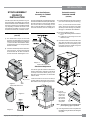
STOVE ASSEMBLY
PRIOR TO
INSTALLATION
All units require either the pedestal or 4 legs at-
tached to the base. The F2400M stove requires
either the Airmate or Rear Heat Deector on top
of the stove. Clearances to combustible materials
vary depending on whether the airmate or rear
heat deector is installed, so be sure to check
the Minimum Clearances, Installation section.
Airmate Assembly for F2400M
(850-105)
1) The airmate sits on top of the stove with
the slots in the sides tting over the curved
deector on the rear stove top. See diagram
1. Discard the Rear Heat Deector that is
supplied with the unit, it is not required if the
airmate is installed.
2) Center the airmate and push it forward to the
front of the stove. The back of the airmate
should be level with the back and sides of
the rear heat shield. See Diagrams 2 & 3.
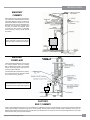
Rear Heat Deector
Assembly for F2400M
(815-555)
The rear heat deector is supplied with the stove
and must be installed unless the optional airmate
has been selected. It stops the heat radiated
from the ue collar from overheating the rear
wall. The rear heat deector is installed on top
of the rear heat shield, as shown in Diagram 4.
Side Shield Adjustment
The left and right side shields are lowered for
shipping and handling. It allows for a handhold
on the top of the stove. Before placing in the
Step Stove in its nal position, the side shields
must be raised.
Loosen the screws on the rear on the stove (3
per side), slide the side panel up as far as pos-
sible and then secure by tightening the screws.
Pedestal Assembly
F2400M & S2400M
(020-925)
1) For easier assembly, tip the stove on its back
(onto a soft surface to prevent scratching).
Hint: If you have chosen the Ash Drawer
option, remove the ash dump cover plates
(knockout) before attaching the pedestal.
See page 17 "Ashdrawer Kit Installation".
2) Remove the blanking plate if
a) you are not installing outside combustion
air or
b) outside air is to be brought in from the
rear of the stove.
3) Unscrew the 4 bolts in the under-side of the
stove. Align the holes in the corners of the
pedestal top with the corresponding holes
in the base of the stove. Fasten using a bolt
and washer for each corner.
4) Push the
Regency logo
into the two
holes in the
front bottom
left corner of
the pedestal
cover plate.
Note: Any paint touch up should be done
prior to placing logo on pedestal.
5) If not using ash drawer, then cover plate must
be installed. If using ash drawer, then disregard
cover plate.
Side Shield
Diagram 1
Diagram 4
Shown with classic door
Shown with classic door

12
Regency 2400 Freestanding Woodstove
INSTALLATION
Horizontal Installation
Standard Ceiling Installation
8) To complete your chimney installation, install
the double wall connector pipe from the
stove’s ue collar to the chimney support
device.
9) If you are using a horizontal connector,
the chimney connector should be as high
as possible while still maintaining the 18"
(457mm) minimum distance from the hori-
zontal connector to the ceiling.
10) NOTE: Residential Close Clearance and
Alcove installations require a listed dou-
ble wall connector from the stove collar
to the ceiling level.
The diagrams below illustrate one way to install
your unit into a standard ceiling or with a horizon-
tal connector. Check with your dealer or installer
for information on other options available to you.
STEP-BY-STEP
CHIMNEY AND
CONNECTOR
INSTALLATION
Note: These are a generic set of chimney in-
stallation instructions. Always follow
the manufacturers own instructions
explicitly. Verify the Minimum Recom-
mended Heights for Woodstove Flue
(Table 1 in the Installation section).
1) With your location already established, cut
and frame the roof hole. It is recommended
that no ceiling support member be cut for
chimney and support box installation. If it is
necessary to cut them, the members must
be made structurally sound.
2) Install radiant shield and support from above.
3) Stack the insulated pipe onto your nish
support to a minimum height of 3 feet above
the roof penetration, or 2 feet above any
point within 10 feet measured horizontally.
There must be at least 3 feet of chimney
above the roof level.
Note: Increasing the chimney height above
this minimum level will sometimes
help your unit to “breathe” better
by allowing a greater draft to be cre-
ated. This greater draft can decrease
problems such as, difcult start-ups,
back-smoking when door is open, and
dirty glass. It might be sufcient to
initially try with the minimum required
height, and then if problems do arise
add additional height at a later date.
4) Slide the roof ashing over your chimney
and seal the ashing to the roof with roong
compound. Secure the ashing to your roof
with nails or screws.
5) Place the storm collar over the ashing,
sealing the joints with a silicone caulking.
6) Fasten the raincap with spark screens (if
required) to the top of your chimney.
7) For optimum efciency when installing into
a masonry chimney, size accordingly, i.e.
the 6" (152mm) ue dia. is 28.28 sq.in.
Leg and Bottom Shield Assembly
F2400M & S2400M
Bottom Shield 020-911
Legs (set of 4)
Cast - Painted Black 850-126
Cast - Gold Plated 850-127
Cast - Brushed Nickel 850-128
The instructions below apply to the steel leg,
painted cast leg and the gold plated cast leg. It
will be easier to attach the legs to the stove if
the stove is tipped on its back (preferably on a
soft surface to prevent scratching). Ensure to be
extremely careful when tipping stove.
1) Remove the 4 bolts from underside of the
base of the pedestal and discard. Also
remove cover plate and put to the side.
2) Line up the heat shield with the bottom of
the unit.
3) Start threading the bolt and washer (supplied
with the bottom shield) for about 1/4 of the
way through the leg with the washers being
underneath the legs. Ensure that the legs
are properly aligned with heat shield and
tighten the bolts.
4) Level the stove by adjusting the levelling
bolts in the bottom of each leg.
5) Reinstall cover plate.
6) Install logo plate onto heat shield by placing
in 2 holes as shown in diagram.
If you are installing outside combustion air, bend
the tabs out 90 degrees. Pipe fresh air into the
bottom shield by using a minimum 4" duct pipe
with a mesh grill at the outside termination. At-
tach the pipe to the 2 tabs with screws.

Regency 2400 Freestanding Woodstove
13
INSTALLATION
FACTORY
BUILT CHIMNEY
When a metal prefabricated chimney is used, the manufacturer's installation instructions must be followed. You must also purchase and install the
ceiling support package or wall pass-through and "T" section package, restops (where needed), insulation shield, roof ashing, chimney cap, etc.
Maintain proper clearance to the structure as recommended by the manufacturer. The chimney must be the required height above the roof or other
obstructions for safety and proper draft operation.
MASONRY
CHIMNEY
Ensure that a masonry chimney meets the mini-
mum standards of the National Fire Protection
Association (NFPA) by having it inspected by
a professional. Make sure there are no cracks,
loose mortar or other signs of deterioration and
blockage. Have the chimney cleaned before
the stove is installed and operated. When
connecting the stove through a combustible
wall to a masonry chimney, special methods
are needed.
MASONRY
FIREPLACE
There are listed kits available to connect a stove
to a masonry replace. The kit is an adapter
that is installed at the location of the replace
damper. The existing damper may have to be
removed to allow installation.
This unit is designed to use either a 5.5" (140mm)
or 6" (152mm) ue liner only within the connes
of the masonry chimney as shown.
Liner
Listed
When referencing installation or connection to
masonry replaces or chimneys, the masonry
construction must or shall be code complying.
When referencing installation or connection to
masonry replaces or chimneys, the masonry
construction must or shall be code complying.

14
Regency 2400 Freestanding Woodstove
INSTALLATION
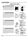
Method A: 12" (304.8 mm) Clearance to Combustible Wall
Member:
Using a minimum thickness 3.5" (89 mm) brick and a 5/8" (15.9 mm)
minimum wall thickness clay liner, construct a wall pass-through.
The clay liner must conform to ASTM C315 (Standard Specication
for Clay Fire Linings) or its equivalent. Keep a minimum of 12" (304.8
mm) of brick masonry between the clay liner and wall combustibles.
The clay liner shall run from the brick masonry outer surface to the
inner surface of the chimney ue liner but not past the inner surface.
Firmly grout or cement the clay liner in place to the chimney ue liner.
Method B: 9" (228.6 mm) Clearance to Combustible Wall Member:
Using a 6" (152.4 mm) inside diameter, listed, factory-built Solid-Pak
chimney section with insulation of 1" (25.4 mm) or more, build a wall
pass-through with a minimum 9" (228.6 mm) air space between the
outer wall of the chimney length and wall combustibles. Use sheet
metal supports fastened securely to wall surfaces on all sides, to
maintain the 9" (228.6 mm) air space. When fastening supports to
chimney length, do not penetrate the chimney liner (the inside wall
of the Solid-Pak chimney). The inner end of the Solid-Pak chimney
section shall be ush with the inside of the masonry chimney ue, and
sealed with a non-water soluble refractory cement. Use this cement
to also seal to the brick masonry penetration.
Minimum
12 in. (304.8mm)
to combustibles
Masonry chimney
Chimney Flue
Minimum chimney clearance to brick
and combustibles 2 in. (50.8mm)
Minimum clearance
12 in. (304.8mm)
of brick
Chimney
connector
Fire clay
liner
Method C: 6" (152.4 mm) Clearance to Combustible Wall Member:
Starting with a minimum 24 gage (.024" [.61 mm]) 6" (152.4 mm) metal
chimney connector, and a minimum 24 gage ventilated wall thimble
which has two air channels of 1" (25.4 mm) each, construct a wall
pass-through. There shall be a minimum 6" (152.4) mm separation area
containing berglass insulation, from the outer surface of the wall thimble
to wall combustibles. Support the wall thimble, and cover its opening
with a 24-gage minimum sheet metal support. Maintain the 6" (152.4
mm) space. There should also be a support sized to t and hold the
metal chimney connector. See that the supports are fastened securely
to wall surfaces on all sides. Make sure fasteners used to secure the
metal chimney connector do not penetrate chimney ue liner.
Method D: 2" (50.8 mm) Clearance to Combustible Wall Member:
Start with a solid-pak listed factory built chimney section at least
12" (304 mm) long, with insulation of 1" (25.4 mm) or more, and an
inside diameter of 8" (2 inches [51 mm] larger than the 6" [152.4
mm] chimney connector). Use this as a pass-through for a minimum
24-gage single wall steel chimney connector. Keep solid-pak section
concentric with and spaced 1" (25.4 mm) off the chimney connector
by way of sheet metal support plates at both ends of chimney section.
Cover opening with and support chimney section on both sides with
24 gage minimum sheet metal supports. See that the supports are
fastened securely to wall surfaces on all sides. Make sure fasteners
used to secure chimney ue liner.
COMBUSTIBLE WALL CHIMNEY
CONNECTOR PASS-THROUGHS

Regency 2400 Freestanding Woodstove
15
INSTALLATION
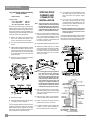
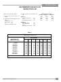
RECOMMENDED HEIGHTS FOR
WOODSTOVE FLUE
Simple rules on draft (refer to Table 1).
1) At sea level minimum height is 12'
straight.
2) Add the following vertical height to compen-
sate for:
45 deg. elbow = 1 ft.
90 deg. elbow = 2 ft.
"T" = 3 ft.
Each foot of horizontal run = 2 ft.
3) Add 4% overall for each 1000' above sea
level.
Example: a)
1-1/2 ft. of horizontal run = 3 ft.
one "T" = 3 ft.
Total Addition (at sea level) = 6 ft.
Example: b)
One 90 deg. elbow = 2 ft.
2 ft. of horizontal run = 4 ft.
one "T" = 3 ft.
Total Addition (at sea level) = 9 ft.
Recommended Flue Height
Elevation Example a) Example b)
0' 18' 21'
1000' 18.72' 21.84'
2000' 19.44' 22.68'
5000' 21.60' 25.20'
8000' 23.76' 27.72'
TABLE 1
MINIMUM RECOMMENDED FLUE HEIGHTS IN FEET
(Measured from the top of the unit)
# OF ELBOWS
ELEVATION (FT)
ABOVE SEA LEVEL 0 2 x 15
o
4 x 15
o
2 x 30
o
4 x 30
o
2 x 45
o
4 x 45
o
0-1000 12.0 13.0 14.0 15.0 18.0 16.0 20.0
1000-2000 12.5 13.5 14.5 15.5 19.0 16.5 21.0
2000-3000 13.0 14.0 15.0 16.0 19.5 17.0 21.5
3000-4000 13.5 14.5 15.5 17.0 20.0 18.0 22.5
4000-5000 14.0 15.0 16.0 17.5 21.0 18.5 23.0
5000-6000 14.5 15.5 17.0 18.0 21.5 19.0 24.0
6000-7000 15.0 16.0 17.5 18.5 22.5 20.0 25.0
7000-8000 15.5 16.5 18.0 19.0 23.0 20.5 25.5
8000-9000 16.0 17.0 18.5 20.0 24.0 21.0 26.5
9000-10000 16.5 17.5 19.0 20.5 24.5 22.0 27.0
NOTE: No more than two offsets (four elbows) allowed. Two 45
o
elbows equal one 90
o
elbow.

16
Regency 2400 Freestanding Woodstove
INSTALLATION
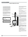
MOBILE HOME INSTALLATION
Once you have properly marked the position of
your unit and the oor protection as outlined in
the Residential Installation items #1 through #8,
a supply of fresh air has to be supplied to your
unit. Cut a minimum 4" (102mm) diameter hole
through your oor protector and the oor directly
under your pedestal base to the outside. Use 4"
(102mm) duct pipe with a mesh grill to pipe fresh
air into the pedestal area. Block off the hole in
the back of the pedestal with the square plate
and the two 1/2" screws provided.
Place your unit in position and secure it to the
oor using two lag bolts 3/8" (10mm) x 3-1/2"
(89mm) through the two holes inside the pedestal
base. It is important to maintain the structural
integrity of the Mobile Home oor, walls and roof
when installing your unit.
For Mobile Home units installed in the U.S. the
unit must be grounded using a #8 ground wire
with approved termination and star washer.
In addition to standard installation instructions
the following requirements are mandatory for
installation in a mobile home.
1) The stove must be permanently bolted to
the oor of the Mobile Home using the oor
screws provided.
2) The stove must have a permanent outside
air source for combustion.
3) The stove must be electrically grounded to
the steel chassis of the Mobile Home.
4) A listed double-wall connector chimney
system, roof thimble, spark arrestor and roof
ashing kit suitable for use in Mobile Homes
must be used.
5) If the chimney exits the Mobile Home at a
location other than through the roof, and exits at
a point 7ft. (2130mm) or less above the ground
level on which the Mobile Home is positioned a
guard or method of enclosing the chimney shall
be tted at the point of exit for a height up to
7ft. (2130mm).
6) The chimney shall be attached directly to
the room heater and shall extend at least 3 ft.
(914mm) above the part of the roof through
which it passes. The top of the chimney should
project at least 2ft. (610mm) above the highest
elevation of any part of the Mobile Home within
10 ft. (3048mm) of the chimney.
7) The chimney system shall comply with Local
Requirements.
8) Any openings in a chimney guard where
required must not permit the entrance of 3/4"
(19mm) diameter rod.
9) CAUTION: THE STRUCTURAL INTEGRITY
OF THE MOBILE HOME ROOF, FLOOR,
WALLS AND CEILING MUST BE MAIN-
TAINED.
10) Check any other local building code as other
local codes may apply.
11) WARNING: DO NOT INSTALL IN A SLEEP-
ING ROOM OF A MOBILE HOME.
12) Use silicone to create an effective vapour
barrier at the location where the chimney or
other component penetrates to the exterior of
the structure.
CAUTION: At no time use unlabelled
parts, or substitute parts made for another
chimney system.
Install as per chimney manufacturer's
installation instructions.
WARNING: Operate only with door fully
closed - open feed door to feed re only.

Regency 2400 Freestanding Woodstove
17
INSTALLATION
Slide the tube into the left hand side, as far
as possible and then bring it back into the
hole on the right hand side until it locks into
position. If the tube will not slide in easily,
simply use a pair of vise grips or pliers and
tap it into place with a hammer. A tighter t
will ensure the tube will not move when the
unit is burning.
2) Slide the left bafe over the air tubes from
the front and then push it to the back.
SIMPSON DURA-PLUS
Qty.Part # Description
1 6DVL8693 Connector Kit
1 6DP-MH9096 Mobile Home Kit
ICC EXCEL 2100
Qty.Part # Description
1 6CL48 48" Chimney length (also in
12", 18", 24" lengths.
1 6RC Rain Cap
1 6RCS Spark Screen (for rain cap)
1 6RDS/SQS Round/Square support box
1 6VF Flashing
1 6UBA "Ultrablack" Close Clearance
Connector
Canadian Installations*
SECURITY S2100 (see above for details)
ICC EXCEL 2100 (see above for details)
SELKIRK SENTINAL CF
*The use of alternate pitch ashings, support
box extensions, additional chimney lengths, and
additional chimney bracing, may be used on each
of the previously listed systems. These parts
though must be from the same system as listed,
and must be a similar and/or complimentary part.
CAUTION: At no time use unlabelled
parts, or substitute parts made for
another chimney system.
Install as per chimney manufacturer's instal-
lation instructions.
FLUE BAFFLE &
SECONDARY AIR TUBE
INSTALLATION
The ue bafe system located in the upper area
of the rebox is removable to make cleaning
your chimney system easier. The bafes must
be installed prior to your rst re. Smoke
spillage and draft problems may occur if
the bafes are improperly positioned. Check
the position of the bafes on a regular basis as
they can be dislodged if too much fuel is forced
into the rebox.
Freestanding Stove
F2400M
The unit arrives with the 2 bafes on the oor
of the rebox.
1) If all 4 air tubes are installed continue on to
Step 2), if not, follow the instructions below.
Install the air tube into the holes in the side
channels. The notch goes on the right hand
side with the air holes facing toward the door.
LISTED COMPONENTS
FOR MOBILE HOME
INSTALLATION
The Regency F2400M and S2400M Freestand-
ing pedestal units are approved for installation
in a Mobile Home if one of the following pipe
systems is used.
U.S. Installation*
METALBESTOS SSII
Qty. Part # Description
1 6DS-VK Connector Kit
1 6TMH Shield/Support
1 6TAF-6 Flashing
1 6T-36 Chimney Length
1 6T-18 Chimney Length
1 6T-CT Rain Cap
PRO-JET 3103
Qty.Part # Description
1 PV06-TK Connector
1 CSB Shield/Support
1 RRS Radiation Shield
1 LFR03 Flashing
1 SL3 Chimney Length
1 SL1 Chimney Length
1 RCSA Rain Cap
SECURITY ASHT
Qty.Part # Description
1 DL42A-6 Connector Kit
1 6SS Shield/Support
1 6FAMH Flashing
1 6L3 Chimney Length
1 6L1 Chimney Length
1 CPE Rain Cap
SECURITY S2100
Qty.Part # Description
1 DL42A-6 Connector Kit
1 6XSF Support
1 6XFA Flashing
1 6XL3 Chimney Length
1 6XL18 Chimney Length
1 6XCPE Rain Cap
METAL-FAB TEMP/GUARD 2100
Qty.Part # Description
1 6DWBK Connector
1 6TGRS Roof Support
1 6TGG36 Chimney Length
1 6TGG12 Chimney Length
1 6TGF Flashing
1 6TGC Rain Cap
AMERI-TEC HS
Qty.Part # Description
1 6DCC Connector
1 6HSRS-12 Roof Support
(6PLRS-12-BK)
1 6F Flashing
1 6HS-36 Chimney Length
1 6HS-18 Chimney Length
1 6HS-RCS Rain Cap (6PL-MPC)
3) Tilt the left bafe up on top of the side chan-
nel and it will leave enough room to position
the right bafe in the same manner as Step
1) above. Then reposition the left bafe at
on the air tubes.
4) Important: push both bafes so they are
tight against the side walls.
Note: When getting the chimney cleaned,
push the bafes forward toward the
front of the stove, this should leave
sufcient access to the ue. If it is
not enough space then remove the
middle air tube (reverse the procedure
in step 1) above), and bafe and then
replace everything when cleaning is
completed.
Side View
Front View
Front View

18
Regency 2400 Freestanding Woodstove
INSTALLATION
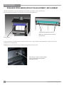
STAINLESS STEEL SMOKE DEFLECTOR ADJUSTMENT / REPLACEMENT
The stainless smoke deector is located in the upper front area of the rebox. The deector is held in place with 2 bolts
Prior to the rst re, ensure deector is seated properly and secured with 2 hand tightened bolts.
To replace the deector, loosen o both bolts and slide defector upward and out. Install new defector and hand tighten bolts. Ensure positive location of
the deector prior to hand tightening.
WARNING: Operation of the unit with out proper installation of smoke deector will void warranty.
Smoke deector installed with 2 bolts.
Note: This is a view from the back of the unit
through the top.
Ensure defector is seated so bolts are situated
at the top of the keyhole before tightening.
Hand tighten bolts only.
Smoke deector

Regency 2400 Freestanding Woodstove
19
INSTALLATION
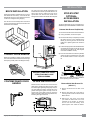
GLASS INSTALLATION
Remove the door from the stove and remove the
glass retainer. Position the glass in the door, make
sure that the glass gasketing will properly seal your
unit, and replace the retainer, it should rest on the
gasket not the glass. Tighten securely, but do not
wrench down on the glass as this may cause the
glass to break. Be careful of the edge clearances,
maintain glass edge clearances.
BRICK INSTALLATION
Firebrick is included to extend the life of your stove
and radiate heat more evenly. Check to see that
all rebricks are in their correct positions and have
not become misaligned during shipping.
The "AD" brick in the drawings below is the brick
covering the Ash Dump hole that is used when the
Ash Drawer Kit is installed.
CLASSIC DOOR HANDLE
Attach spring handle by rotating counter clockwise
onto rod. Ensure that the rod ts into the entire length
of the spring handle (refer to the Diagram below).
CONTEMPORARY DOOR
HANDLE
STEP-BY-STEP
OPTIONAL
ACCESSORIES
INSTALLATION
The pieces listed below can be purchased and in-
stalled during the initial installation or added on later.
Pedestal Ash Drawer Kit (850-100)
1) Remove the bricks from the oor of the rebox.
2) If using ashdrawer, discard cover plate.
3) Remove the ash dump cover plates (one inside
the rebox and one on the underside of the
rebox) by removing the two nuts and bolts
holding the 2 plates together from inside the
rebox.
4) Push the ash plug into the hole inside the rebox
and replace all the bricks except for the brick
over the ash plug (refer to the brick diagram
in the Brick Installation section).
5) Place the ash drawer lid inside the pedestal,
and the ash plug tool beside the lid, then slide
the ash drawer inside so it sits on top of the
lid.
Refer to the Ash Drawer Operating Guidelines
in the Operating Instructions section.
Bottom Shield Ash Drawer Kit
(850-101 )
1) Remove the bricks from the oor of the
rebox.
2) Remove and discard the cover plate by
removing the two screws on the front of the
Bottom Shield.
3) Remove the ash dump cover plates
(one inside the rebox and one on the
underside of the rebox) by removing
the two nuts and bolts holding the 2
plates together from inside the rebox.
The cool to touch door handle is designed to be
inserted from the bottom up and slide off when not
held in place. Once in position, the door can be
opened. After use, store the door handle on the
storage hook located on the left side of the faceplate
Handle
Hook
WARNING: FAILURE TO USE RE-
MOVABLE HANDLE AS PER IN-
STRUCTIONS MAY CAUSE
SERIOUS BURNS.

20
Regency 2400 Freestanding Woodstove
INSTALLATION
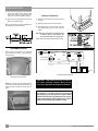
Blower/Fan (846-515)
1) Remove the two screws from the top of the fan
housing.
2) Slide the fan up into the rear heat shield.
3) After aligning holes, secure the fan to the rear
heat shield using the two screws removed
earlier.
CAUTION: The connection cord should not be
in contact with any hot surfaces. Do
not route cord under or in front of unit.
Read the Fan Operation instructions before using.
Ground
Fan Fan
Ground
Green
Neutral
Live
White
Fan
Switch
Manual/
Auto
Switch
Black Black
High (Black)
Low (Red)
Black
Fan Thermodisc
(normally open)
120V AC
60 Hz
Blower/Fan Wiring Diagram
CAUTION: Label all wires prior to disconnec-
tion when servicing controls. Wiring errors
can cause improper and dangerous operation.
WARNING: Electrical Grounding Instructions
This appliance is equipped with a three pronged
(grounding) plug for your protection against shock
hazard and should be plugged directly into a prop-
erly grounded three-prong receptacle. Do not cut or
remove the grounding prong from this plug.
SCREEN DOOR
Hook screen to the inside on the right side
of the rebox door opening. Lock in place by
turning handle.
Back Side of Screen Shown
4) Push the ash plug into the hole inside the
rebox and replace all the bricks except
for the brick over the ash plug (see brick
diagram in the Brick Installation section).
5) Place the ash plug tool beside the lid, then
slide the ash drawer inside.
Refer to Ash Drawer Operating Guidelines in
the Operating Instructions section.
NOTE: The handle must be positioned at 10
o'clock when closed to avoid the handle from
getting hot and to ensure the screen stays in
place.
Handle Lock
Hooks
Handle at 10 o'clock position.
La page est en cours de chargement...
La page est en cours de chargement...
La page est en cours de chargement...
La page est en cours de chargement...
La page est en cours de chargement...
La page est en cours de chargement...
La page est en cours de chargement...
La page est en cours de chargement...
La page est en cours de chargement...
La page est en cours de chargement...
La page est en cours de chargement...
La page est en cours de chargement...
-
 1
1
-
 2
2
-
 3
3
-
 4
4
-
 5
5
-
 6
6
-
 7
7
-
 8
8
-
 9
9
-
 10
10
-
 11
11
-
 12
12
-
 13
13
-
 14
14
-
 15
15
-
 16
16
-
 17
17
-
 18
18
-
 19
19
-
 20
20
-
 21
21
-
 22
22
-
 23
23
-
 24
24
-
 25
25
-
 26
26
-
 27
27
-
 28
28
-
 29
29
-
 30
30
-
 31
31
-
 32
32


Regency Fireplace Products Classic F2400 Le manuel du propriétaire
- Catégorie
- Cheminées
- Taper
- Le manuel du propriétaire
- Ce manuel convient également à
dans d''autres langues
Documents connexes
-
 Regency Fireplace Products Classic S2400 Le manuel du propriétaire
-
 Regency Fireplace Products Alterra CS2400 Le manuel du propriétaire
-
 Regency Fireplace Products Pro-Series F3500 Le manuel du propriétaire
-
 Regency Fireplace Products RI50 Le manuel du propriétaire
-
 Regency Fireplace Products Classic F2450 Le manuel du propriétaire
-
 Regency Fireplace Products Energy U23 Le manuel du propriétaire
-
 Regency Fireplace Products Alterra CF780 Le manuel du propriétaire


Autres documents
-
United States Stove AWC21M Le manuel du propriétaire
-
United States Stove Company VG1120 Series Le manuel du propriétaire
-
US Stove Company Defender II Le manuel du propriétaire
-
-
-
-
Ashley Hearth Products Hearth AW3200E EPA Certified Pedestal Wood Burning Stove Manuel utilisateur
-
DutchWest DW2500X02 Le manuel du propriétaire
-
Regency F1100S Owners & Installation Manual
-
MHSC WR2500X02 Le manuel du propriétaire