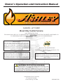
Ashley AF1500E Le manuel du propriétaire
- Catégorie
- Poêles
- Taper
- Le manuel du propriétaire

853128B-3705H
United States Stove Company
227 Industrial Park Rd.
South Pittsburg, TN 37380
U.S. ENVIRONMENTAL PROTECTION AGENCY
Certied to comply with the 2016 particulate
emission standards. Not approved for sale after
May 15, 2020
Wood Only Central Furnace
Owner’s Operation and Instruction Manual
MODEL: AF1500E
SAVE THESE INSTRUCTIONS
THIS MANUAL WILL HELP YOU TO OBTAIN EFFICIENT, DEPENDABLE SERVICE FROM THE HEATER, AND ENABLE YOU
TO ORDER REPAIR PARTS CORRECTLY. KEEP IN A SAFE PLACE FOR FUTURE REFERENCE.
SAFETY NOTICE:
If this unit is not properly installed, a re may result.
For your safety, follow the installation instructions.
Never use make-shift compromises during the
installation of this unit. Contact local building or re
ofcials about permits, restrictions and installation
requirements in your area.
CAUTION!
Please read this entire manual before you install or
use this unit. Failure to follow instructions may result
in property damage, bodily injury, or even death.
Improper Installation Could Void Your Warranty!
Certied to: UL-391 (R2015) and Certied to: CSA
B266.1-11 (R2014)
Report No. 0215WH055S.REV002
CALIFORNIA PROPOSITION 65 WARNING:
This product can expose you to chemicals including carbon monoxide, which
is known to the State of California to cause cancer, birth defects and/or other
reproductive harm. For more information, go to www.P65warnings.ca.gov
Ce produit peut vous exposer à des produits chimiques, y compris le
monoxyde de carbone, qui est connu dans l'État de Californie pour causer
le cancer, des malformations congénitales et / ou d'autres problèmes de
reproduction. Pour plus d'informations, visitez www.P65warnings.ca.gov

-2-
CAUTION:
• Power source not controlled by furnace main disconnect.
• Respect all local and national codes when installing this unit.
• This unit is not to be connected to a chimney flue serving another appliance.
• This unit is designed to burn solid hardwood only.
40
34
33.75
2.33
57.77
24.14

-3-
Specications
CONGRATULATIONS!
You’ve purchased a heater from North America’s oldest manufacturer of wood burning products.
By heating with wood you’re helping to CONSERVE ENERGY!
Wood is our only Renewable Energy Resource. Please do your part to preserve our wood supply. Plant at least
one tree each year. Future generations will thank you.
This manual describes the installation and operation of the Ashley, AF1500E wood heater. This heater meets
the 2016 U.S. Environmental Protection Agency’s emission limits for wood heaters sold after May 15, 2016. Under
specic EPA test conditions this heater has been shown to deliver heat at a rate of 18,850 – 56,000 BTU/hr. This
heater achieved a particulate emissions rate of 0.39 lb/mmBtu when tested to method CSA B415.1-10 (*and an
overall efciency of 62.6 %). The maximum overall heat output of this heater was tested to be 89,000 Btu/hr.
This wood heater has a manufacturer-set minimum low burn rate that must not be altered. It is against federal
regulations to alter this setting or otherwise operate this wood heater in a manner inconsistent with operating
instructions in this manual.
The operation of this wood heater in a manner inconsistent with the owner’s manual will void you warranty and
is also against federal regulations.
This heater is designed to burn natural wood only. Higher efciencies and lower emissions generally result when
burning air dried seasoned hardwoods, as compared to softwoods or to green or freshly cut hardwoods.
This wood heater needs periodic inspection and repair for proper operation. It is against federal regulations to
operate this wood heater in a manner inconsistent with operating instructions in this manual.
Combustible: Wood
Flue Pipe Diameter: 6” (153cm)
Flue Pipe Type: (Standard,
Single Wall, or Double Wall):
Black or Blued Steel 2100°F (650°C) Class “A”
Minimum Chimney Height: 12’
Maximum Log Length: 27”
Electrical: 120V, 60Hz, 2.6A per blower (5.2A on start up for both blowers)
Dimensions
Combustion Chamber:
Width x Depth:
17.4” X 28.3”
Volume:
Cubic Feet:
5.2 cubic feet
Door Opening: Width x Height: 11.6” X 11.5”
Weight (lbs): 509 lbs.
-2-
CAUTION:
• Power source not controlled by furnace main disconnect.
• Respect all local and national codes when installing this unit.
• This unit is not to be connected to a chimney flue serving another appliance.
• This unit is designed to burn solid hardwood only.
40
34
33.75
2.33
57.77
24.14

-4-
Safety
• WARNING: Do not operate with fuel loading or ash removal doors open.
• Do not connect this unit to a chimney flue serving another appliance.
• WARNING DANGER: Risk of re or explosion. Do not burn garbage, gasoline, naphtha, motor oil, or other
inappropriate materials. Do not use chemicals or fluids to start the re.
• WARNING: Risk of re. Do not operate with flue draft exceeding .060” water column/14.93 Pascals. Do not
operate with fuel loading and ash removal doors open. Do not store fuel or other combustible materials
within marked installation clearances. Inspect and clean flues and chimney regularly.
• CAUTION: Hot surfaces. Keep children away. Do not touch during operation.
• The heat exchanger, flue pipe, and chimney must be cleaned regularly to remove accumulated creosote
and ash. Ensure that the heat exchanger, flue pipe, and chimney are cleaned at the end of the heating
season to minimize corrosion during the summer months. The appliance, flue pipe, and chimney must be
kept in good condition. These instructions also apply to a draft inducer if used. To prevent flame or smoke
spillage, the slide baffle must be pulled out and the fuel loading door left cracked for 10 seconds prior to
opening door fully. Load fuel carefully or damage may result.
• Hot while in operation. Keep children, clothing and furniture away. Contact may cause skin burns.
• Do not use chemicals or fluids to ignite the re.
• Do not leave the furnace unattended when the door is slightly opened.
• Do not burn garbage, flammable fluid such as gasoline, naphtha or motor oil.
• Always close the door after the ignition.
• Consult your municipal building department or re ofcials about permits, restrictions and installations
requirements in your area.
• INSPECT FLUE PIPES, FLUE PIPE JOINTS, AND FLUE PIPE SEALS REGULARLY TO ENSURE THAT SMOKE AND FLUE
GASES ARE NOT DRAWN INTO, AND CIRCULATED BY, THE AIR-CIRCULATION SYSTEM.
• CAUTION: CLEAN OUT OF THE HEAT EXCHANGER, FLUE PIPE CHIMNEY, AND DRAFT INDUCER, IF USED, IS
ESPECIALLY IMPORTANT AT THE END OF THE HEATING SEASON TO MINIMIZE CORROSION DURING THE SUMMER
MONTHS, CAUSED BY ACCUMULATED ASH.
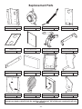
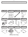
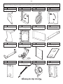
Unpacking And Preassemble
UNPACKING
1. Remove all packaging from the furnace.
2. Remove the supplied parts from the furnace.
BRICK ALIGNMENT
Inspect for any damage. Ensure that the bricks and ash plug are positioned correctly and not broken (see
illustration for proper brick arrangement).
TOOLS AND MATERIALS NEEDED FOR INSTALLATION
The following is a list of tools and materials needed to install
your furnace.
• 7/16” socket wrench.
• 5/16” socket (Best if using a power drill and a socket bit).
• Pair of pliers or channel-locks.
• Power drill with an 1/8” drill bit to install sheet metal screws
into connector pipe..
• Sheet metal screws.
• Non-combustible floor protector as specied in this
manual.
• All chimney and chimney connector components
required for your particular venting installation..
• Electrical wiring tools and supplies.
• Ductwork for supply and return air.
Proper Fire Brick Alignment

-5-
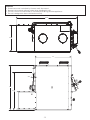
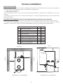
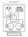
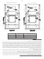
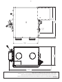
Furnace Installation
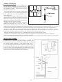
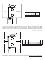
Dimension Inch mm
A Backwall to Furnace 28 712
B Sidewall to Furnace 16 407
C Sidewall to Flue 25 635
D Backwall to Flue 18 458
E Supply Duct (rst 6 feet) 6 153
F Supply Duct (after rst 6 feet) 1 26
G Minimum Duct height 8 204
H Top of Door to Ceiling 48 1220
J Minimum Ceiling Height 77 1956
INSTALLATION OPTIONS
The installation of this furnace includes supplying electrical power, return (fresh air) ductwork, and supply air
ductwork. This furnace may be installed in two different congurations.
1. Stand alone wood furnace
2. Add-on wood furnace
See kit installation section in this manual to ensure proper assembly, installation and operation of your new
furnace.
If installing in an area with a fan it should not be allowed to create negative pressure in the room where the
furnace is installed.
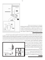
LOCATING YOUR FURNACE (INSURE THAT THE REQUIRED MAINTENANCE CLEARANCES ARE MAINTAINED)
Your furnace must be installed as shown in this manual and in compliance with all local and national codes.
It is of the utmost importance that the clearances to combustible materials be strictly adhered to during
installation of the furnace. Refer to the table and diagrams below for minimum required clearances.
CLEARANCE TO COMBUSTIBLESCLEARANCE TO COMBUSTIBLES
Back wall
Side wall
Side wall
C
B
A
Ceiling
Floor Protector
E
F
G
H
J
D

-6-
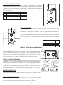
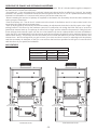
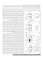
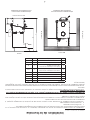
MAINTENANCE CLEARANCES
Your furnace has recommended minimum maintenance clearance
requirements. These clearances insure that there is adequate room to preform
maintenance and service your furnace. DO NOT store fuel within the specied
clearances. See the table and diagram below to determine the clearances
for your furnace.
Dimension Inch mm
K Maintenance Clearance (Front) 24 610
L Maintenance Clearance (Left) 24 610
M Maintenance Clearance (Right) 24 610
N Maintenance Clearance (Rear) 36 915
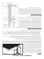
FLOOR PROTECTOR REQUIREMENTS
FLOOR PROTECTOR
The furnace must be placed on solid concrete, solid masonry, or when
installed on a combustible floor, on a floor protector. The floor protector is
required to provide heat, live ember, and ash protection and must be of a
non-combustible, continuous solid surface to protect against inltration of
live embers and ash. Floor protection must have and R-Value of at least 2.8.
Refer to floor protector manufacturer’s instructions for installation directions.
The floor protector or non combustible floor must extend under the furnace
and beyond each side as shown below.
Dimension Inch mm
O* Front 16 407
P Flue rear 2 51
Q** Left 8 204
R** Right 8 204
S Flue Side 2 51
Duct Work Installation
We strongly recommend that the hot air ductwork be installed by a home
heating specialist. If doing the installation yourself, before you decide
which installation will best suit your needs, consult a qualied heating
technician and follow his recommendations as to the safest and most
efcient method of installation. This furnace can be installed in three ways,
as a stand alone unit, parallel, and in series with an existing furnace.
SUPPLY AIR (HOT AIR) PLENUM
The warm-air supply duct shall be constructed of metal in accordance with
NFPA 90B, 2-1.1. The plenums installed to the furnace shall be constructed
of metal in accordance with NFPA 90B, 2-1.3. When installing this furnace
the hot air plenum is to have a minimum height of 24” (610mm) if the top
of the rst vertical section is not flush with the top of the rst horizontal
section of ductwork. If the top of the plenum is flush with the top of the
rst horizontal section of ductwork then the minium height is 15” (381mm).
RETURN AIR (FRESH AIR)
The return (fresh) air intake on the furnace is on the rear of the unit. The
ductwork must be mechanically attached to the unit or UFB908 blower
box with sheet metal screws to ensure a proper operation.
STAND ALONE INSTALLATION
If installing this furnace as a stand alone unit, ensure all local codes
and all instructions in this manual are followed, including clearance to
combustibles, floor protector specications and safety warnings.
6”
24 1/16”
Supply Air (Hot Air) Duct Work Outlet Size
Supply Air Plenum
Minimum Height Of 24”
Supply Air Plenum With
Minimum Height Of 15”
MAINTENANCE CLEARANCE
ML
N
K
Q
O
R
P
S
S

-7-
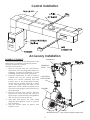
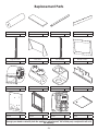
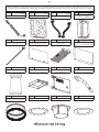
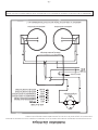
CENTRAL INSTALLATION
Central Installation
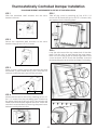
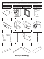
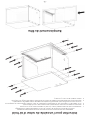
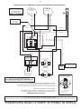
ASSEMBLY OF FURNACE
Your furnace requires the following items to be
assembled or installed by the service person:
Blowers and Blower Controls
Electrical Connections
1. Remove all parts from the unit (blowers,
thermodisc, and all wiring) and inspect for
damage, including the rebrick as some
breakage could occur during shipment.
2. Install the thermodisc on rear of furnace
cabinet with the two screws provided.
Mount the conduit assembly from the
junction box to the thermostat bracket.
Crimp the two female terminals to each
of the wire leads. Plug the wires to the
thermodisc. NOTE: It does not matter which
of the two wires plugs to which terminal on
the thermodisc.
3. Remove blowers from cartons. Remove
junction box cover. Attach clip nuts as in
gure shown. Install blower(s) and gasket(s
with 1/4"-20 x 3/4" bolts as shown.
4. Wire right side blower rst (See wiring
diagram) and replace cover on junction
box on blower.
5. Wire left blower same as above and
replace cover.
Accessory Installation
THERMODISC
THERMODISC
COVER
4” ELECTRICAL
JUNCTION BOX
BLOWERS
BLOWERS GASKET
CLIP NUTS
(Not used in the upper center hole.)

-8-
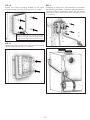
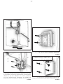
SMOKE CURTAIN
Using two 1/4-20 x 1-1/4” Carriage bolts, two smoke curtain clips, and two nuts, attach the smoke curtain in
place above the fuel feed door as shown. After installation, the smoke curtain should swing freely back into the
furnace.
DOOR LATCH INSTALLATION
Use the two included bolts and nuts to secure the handle to the stove as shown.
Note: Adjust the handle as needed to insure a proper seal.
HEAT SHIELD INSTALLATION

-9-
Electrical Installation
All electrical connections should be done by a qualied electrician
It is recommended to connect the furnace to its own 15 amp 120 Volt circuit from the house power supply
105°C
NOTE: Wire leads from the distribution blower are usually
BOTH BLACK. Makes no difference which leads from the
motor(s) connects to the corresponding leads coming out of
the conduit.

-10-
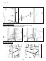
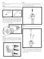
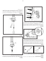
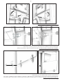
STEP 1
Slide the motorized draft actuator into the servo
bracket as shown.
STEP 2
Secure the motorized draft actuator to the servo
bracket using (2) two #10 X 1/2 screw.
STEP 3
Place (1) one 1/4-20 X 3/4 bolt into the servo arm and
secure with (1) one washer and (1) one 1/4-20 lock nut
as shown. Insert the servo arm into the actuator.
STEP 4
Attach the actuator to the unit by inserting (2) two 10-
24 X 1/2 screws into the pre-drilled holes located on
the upper right side of the unit. NOTE: The actuator will
need to be mounted fl ush against the stove. Insure the
actuator is mounted fl ush by removing the panel screw
before mounting the actuator.
STEP 5
Take off the cover by removing (4) four #10 X 1/2
screws. NOTE: Retain the (4) four #10 X 1/2 screws, they
are required for the following steps.
STEP 6
Loop the wire around the top center bolt of the slide
plate. Run the wire up and through the loop clamp,
then out of the hole found at the top right side of the
cover as shown. NOTE: Check the assembly to ensure
that everything moves smoothly and there is no binding.
Thermostatically Controlled Damper Installation
*CANADIAN RESIDENTS ARE REQUIRED TO USE THIS KIT FOR INSTALLATION.
Servo Arm
Actuator

-11-
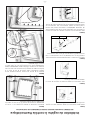
STEP 7
Reattach the cover using the previously removed (4)
four #10 X 1/2 screws.
STEP 8
Insert the wire into the cable clamp make a loop as
shown and then route the wire back through the cable
clamp.
STEP 9
Connect the wire to the servo arm by looping the wire
around the 1/4-20 X 3/4 bolt as shown. After the wire
loop is in position reduce the loop size so that it is smaller
than the washer. This will prevent it from sliding off once
the unit is in operation. Tighten down the two screws so
the wire is not able to move.
STEP 10
Attach the non-adjustable limit switch and adjustable
thermodisc to the back of the unit as shown using
(3) three #10 X 1/2 screws. NOTE: The non-adjustable
limit switch must be installed above the adjustable
thermodisc.
STEP 11
Route the two red wires included with this kit through
the existing conduit that runs from the junction box up
to the T’stat bracket assembly box.
STEP 12
Attach the female terminals to both ends of the red
wires.
STEP 13
Connect the conduit to the thermodisc (see
“Thermostatically Controlled Damper Wiring Diagram”
for proper wiring installation). Reattach the T’stat
bracket assembly to the back of the unit using (4) four
#10 X 1/2 screws.

-12-
STEP 14
Attach the control mounting bracket to the lower
backside of the unit using (4) four #10 X 1/2 screws.
STEP 15
Attach the 4 X 4 junction box to the control mounting
bracket using (2) two #10 X 1/2 screws.
STEP 16
Complete all wiring (see “Thermostatically Controlled
Damper Wiring Diagram” for proper wiring installation).
Once the wiring is completed, attach the fan center
transformer to the control cover base using (4) four #10
X 1/2 screws.
When attaching the control mounting
bracket to the unit insure the large hole is
positioned toward the bottom of the unit.

-13-
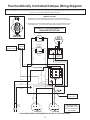
1. DAMPER ACTUATOR DE-ENERGIZES AND REDUCES BURN SETTING
WHEN THE UNIT REACHES TEMPERATURES OF APPROX. 250 DEGREES
2. DISTRIBUTION FANS TEMPERATURE SET-POINT. ADJUSTABE IN APPROX.
5 DEGREE STEPS. A LOW SETTING TURNS THE BLOWER ON SOONER.
THERMAL DISK INFO:
1 3
64
COIL
COIL
5
2
DAMPER
ACTUATOR
HIGH
ADJUSTABLE
(Located on top of the box)
(Located below the high
limit disc.)
FAN CONTROL
CENTER FRONT
WHITE
WHITE
WHITE
WHITE
WHITE
BLACK
BLACK
BLACK
RED
REDRED
BLACK
BLUE
BLUE
BLACK
BLACK
BLACK
GREEN
GROUND
120 VAC
60 HZ
15 AMPS
NOTE: WIRES FROM
DISTRIBUTION FAN RUN
DIRECTLEY INTO THE 4 X 4
JUNCTION BOX.
WHITE
WHITE
WHITE
BLACK
BLACK
BLACK
BLACK
WHITE
Thermostatically Controlled Damper Wiring Diagram
*CANADIAN RESIDENTS ARE REQUIRED TO USE THIS KIT FOR INSTALLATION.
This kit includes two red wires. Route the two red wires through the existing conduit that runs from the junction
box up to the T’stat bracket assembly box.
Use large
wire nut here.
Use two small
wire nuts here.
WIRING IS TO BE PREFORMED BY A
QUALIFIED ELECTRICIAN.

-14-
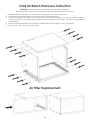
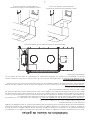
CAUTION: Read all instructions carefully before starting the installation.
The cold air return is made up of 4 parts, plus all hardware necessary for assembly.
1. Assemble the lter box sides, top, and bottom using sixteen (16) #10x1/2 HX screws.
2. Mount the blowers and gaskets to the furnace if not already mounted.
3. If your BX Cables will not match up to the previously matched arrangement on the top, carefully measure
and custom notch to accommodate your particular arrangement of Bx Cables. There are several different
con gurations.
4. Mount both side assemblies to the furnace's cabinet back using eight (8) #10x1/2 HX screws.
5. Insert one 16 x 24 x 1 air lter (not included).
Air Filter Replacement
Cold Air Return Enclosure Instruction

-15-
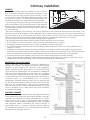
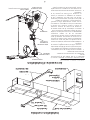
Chimney Installation
CHIMNEY
Your wood furnace may be hooked up with a factory
built or masonry chimney, matching the diameter of the
exhaust. If you are using a factory built chimney, it must
comply with UL 103 or CSA-B365 standard; therefore it must
be a Type HT (2100°F). It is extremely important that it be
installed according to the manufacturer’s specications.
If you are using a masonry chimney, it is important that it be
built in compliance with the specications of the National
Building Code. It must be lined with re clay bricks, metal or
clay tiles sealed together with re cement. (Round flues are
the most efcient).
The interior diameter of the chimney flue must be identical to the furnace smoke exhaust. A flue which is too
small may cause draft problems, while a large flue favors rapid cooling of the gas, and hence the build-up of
creosote and the risk of chimney res. Note that it is the chimney and not the furnace which creates the draft
effect; your furnace’s performance is directly dependent on an adequate draft from your chimney.
Do not connect this unit to a chimney flue serving another appliance.
The following recommendations may be useful for the installation of your chimney:
• It must rise above the roof at least 3’ (0.9m) from the uppermost point of contact.
• The exterior portion should be double or triple wall pipe to ensure proper draft.
• The chimney must exceed any part of the building or other obstruction within a 10’ (3.04m) distance by a
height of 2’ (0.6m).
• Installation of an interior chimney is always preferable to an exterior chimney. The interior chimney will be
hotter than an exterior chimney that is being cooled by the ambient air outside the house. Therefore the gas
which circulates will cool slower, thus reducing the build-up of creosote and the risk of chimney res.
• The draft caused by the tendency for hot air to rise will be increased with an interior chimney.
• Using a re screen at the extremity of the chimney requires regular inspection in order to insure that it is not
obstructed thus blocking the draft, and it should be cleaned when used regularly.
IMPORTANCE OF PROPER DRAFT
Draft is the force which moves air from the appliance up
through the chimney. The amount of draft in your chimney
depends on the length of the chimney, local geography,
nearby obstructions and other factors. Too much draft may
cause excessive temperatures in the appliance. Inadequate
draft may cause back pufng into the room and ‘plugging’
of the chimney. Inadequate draft will cause the appliance
to leak smoke into the room through appliance and chimney
connector joints. An uncontrollable burn or excessive
temperature indicates excessive draft. Do not operate with
the flue draft exceeding .06 water column/14.93 Pascals. The
draft can be checked with a draft gauge or manometer.
Take into account the chimney’s location to insure it is not too
close to neighbors or in a valley which may cause unhealthy
or nuisance conditions.
MASONRY CHIMNEY
Ensure that a masonry chimney meets the minimum standards
of the National Fire Protection Association (NFPA) by having it
inspected by a professional. Make sure there are no cracks,
loose mortar or other signs of deterioration and blockage.
Have the chimney cleaned before the furnace is installed
and operated. When connecting the furnace through a
combustible wall to a masonry chimney, special methods
are needed as explained in the “Combustible Wall Chimney
Connector Pass-Throughs” Section.

-16-
COMBUSTIBLE WALL CHIMNEY CONNECTOR PASS-THROUGHS
Method A. 12” (304.8 mm) Clearance to Combustible Wall
Member: Using a minimum thickness 3.5” (89 mm) brick
and a 5/8” (15.9 mm) minimum wall thickness clay liner,
construct a wall pass-through. The clay liner must conform
to ASTM C315 (Standard Specication for Clay Fire Linings)
or its equivalent. Keep a minimum of 12” (304.8 mm) of brick
masonry between the clay liner and wall combustibles. The
clay liner shall run from the brick masonry outer surface to
the inner surface of the chimney flue liner but not past the
inner surface. Firmly grout or cement the clay liner in place
to the chimney flue liner.
Method B. 9” (228.6 mm) Clearance to Combustible Wall
Member: Using a 6” (152.4 mm) inside diameter, listed,
factory-built Solid-Pak chimney section with insulation
of 1” (25.4 mm) or more, build a wall pass-through with a
minimum 9” (228.6 mm) air space between the outer wall of
the chimney length and wall combustibles. Use sheet metal
supports fastened securely to wall surfaces on all sides, to
maintain the 9” (228.6 mm) air space. When fastening
supports to chimney length, do not penetrate the chimney
liner (the inside wall of the Solid-Pak chimney). The inner end
of the Solid-Pak chimney section shall be flush with the inside
of the masonry chimney flue, and sealed with a non-water
soluble refractory cement. Use this cement to also seal to
the brick masonry penetration.
Method C. 6” (152.4 mm) Clearance to Combustible Wall
Member: Starting with a minimum 24 gauge (.024” [.61 mm])
6” (152.4 mm) metal chimney connector, and a minimum 24
gauge ventilated wall thimble which has two air channels of
1” (25.4 mm) each, construct a wall pass-through. There shall
be a minimum 6” (152.4) mm separation area containing
berglass insulation, from the outer surface of the wall thimble
to wall combustibles. Support the wall thimble, and cover
its opening with a 24-gauge minimum sheet metal support.
Maintain the 6” (152.4 mm) space. There should also be a
support sized to t and hold the metal chimney connector.
See that the supports are fastened securely to wall surfaces
on all sides. Make sure fasteners used to secure the metal
chimney connector do not penetrate chimney flue liner.
Method D. 2” (50.8 mm) Clearance to Combustible Wall
Member: Start with a solid-pak listed factory built chimney
section at least 12” (304 mm) long, with insulation of 1” (25.4
mm) or more, and an inside diameter of 8” (2 inches [51 mm]
larger than the 6” [152.4 mm] chimney connector). Use this
as a pass-through for a minimum 24-gauge single wall steel
chimney connector. Keep solid-pak section concentric with
and spaced 1” (25.4 mm) off the chimney connector by
way of sheet metal support plates at both ends of chimney
section. Cover opening with and support chimney section
on both sides with 24 gauge minimum sheet metal supports.
See that the supports are fastened securely to wall surfaces
on all sides. Make sure fasteners used to secure chimney flue
do not penetrate flue liner.
NOTES:
Connectors to a masonry chimney, excepting method B, shall extend in one continuous section through the
wall pass-through system and the chimney wall, to but not past the inner flue liner face. A chimney connector
shall not pass through an attic or roof space, closet or similar concealed space, or a floor, or ceiling.

-17-
CHIMNEY CONNECTOR
Your chimney connector and chimney must
have the same diameter as the furnace outlet. If
this is not the case, we recommend you contact
your dealer in order to insure there will be no
problem with the draft.
The furnace pipe must be made of aluminized
or cold roll steel with a minimum thickness of
0.021” or 0.53 mm. It is strictly forbidden to use
galvanized steel.
Your connector should be assembled in such a
way that the male section (crimped end) of the
pipe faces down. Attach each of the sections to
one another with three equidistant metal screws.
Seal the joints with furnace cement.
The pipe must be short and straight. All sections
installed horizontally must slope at least 1/4
inch per foot, with the upper end of the section
toward the chimney. Any installation with a horizontal run of furnace pipe must conform to NFPA 211. You may
contact NFPA (National Fire Protection Association) and request the latest edition of the NFPA Standard 211.
To insure a good draft, the total length of the furnace pipe should never exceed 8’ to 10’ (2.4m to 3.04 m).
(Except for cases of vertical installation, cathedral-roof style where the smoke exhaust system can be much
longer and connected without problem to the chimney at the ceiling of the room).
There should never be more than two 90 degrees elbows in the smoke exhaust system.
Installation of a “barometric draft stabilizer” (replace register) on a smoke exhaust system is prohibited.
Do not use with a flue damper. With a controlled combustion wood furnaces the draft is regulated upon intake
of the combustion air in the furnace and not at the exhaust.
FACTORY BUILT CHIMNEY
When a metal prefabricated chimney is used, the
manufacturer’s installation instructions must be followed. You
must also purchase (from the same manufacturer) and install
the ceiling support package or wall pass-through and “T”
section package, restops (where needed), insulation shield,
roof flashing, chimney cap, etc. Maintain proper clearance
to the structure as recommended by the manufacturer. The
chimney must be the required height above the roof or other
obstructions for safety and proper draft operation.
To
Appliance

-18-
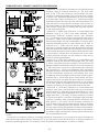
OPERATING THE PRIMARY AND SECONDARY AIR SETTINGS
Primary air- is the driving air supply that feeds the re in the heater. This air is introduced through the damper in
the feed door to sustain the combustion.
Secondary air – is the air supply that is typically introduced above the re to effectively “re-burn” the smoke
created in the primary combustion before the exhaust gasses exit the stove. This air is preheated before being
injected into the heater so it can react with (re-burn) the smoke when they mix.
When increasing the amount of primary air supplied to the heater, the secondary should also be increased as
well to ensure a clean burn.
Rear Pilot/Tertiary Air – The air that is introduced at the back of the rebox and is to help sustain heat in the
secondary air to help ensure a cleaner burn.
Start up: During Start-up the Primary and the Secondary air adjustments should be in the fully open or the “High”
setting positions. This allows for the maximum amount of combustion air during the initial start-up to insure the
fastest and cleanest start-up. The primary air will be in the “High” position when the thermostat is calling for heat.
These settings should remain open until the stove has heated up and an adequate re has been established.
Once the re is well established, both the primary and the secondary air settings can be adjusted down to the
desired heat setting. The primary and the secondary air mix inside the rebox to provide a more efcient and
cleaner burn. We encourage that you get to know your stove and how it reacts to adjusting both the primary
and the secondary air dampers so that you can achieve the best burn possible for the type of wood and the
draft situations in your particular installation.
AIR CONTROL’S
FULLY CLOSED
Rear Pilot Air Damper
FULLY CLOSED
Secondary Air Damper
LOW BURN RATE SETTING
MAXIMUM BURN RATE SETTING
FULLY OPENED
Rear Pilot Air Damper
FULLY OPENED
Secondary Air Damper
AIR CONTROL’S
Low Burn Rate High Burn Rate
Primary Air Damper Fully Closed Fully Open
Rear Pilot Air Damper Fully Closed Fully Open
Secondary Air Damper Fully Closed Fully Open

-19-
Operation
The top down method of re building is recommended for this appliance. After making sure that the stove air
intake controls are fully open (open all three air controls to there maximum setting). Place the largest pieces of
wood on the bottom, laid in parallel and close together. Smaller pieces are placed in a second layer, crossways
to the rst. A third layer of still smaller pieces is laid crossways to the second, this time with some spaces between.
Then a fourth layer of loose, small kindling and twisted newspaper sheets tops off the pile.
Higher efciencies and lower emissions generally result when burning air dried seasoned hardwoods, as
compared to softwoods or to green or freshly cut hardwoods.
DO NOT BURN:
1. Garbage;
2. Lawn clippings or yard waste;
3. Materials containing rubber, including tires;
4. Materials containing plastic;
5. Waste petroleum products, paints or paint
thinners, or asphalt products;
6. Materials containing asbestos;
7. Construction or demolition debris;
8. Railroad ties or pressure-treated wood;
9. Manure or animal remains;
10. Salt water driftwood or other previously salt water
saturated materials;
11. Unseasoned wood; or
12. Paper products, cardboard, plywood, or
particleboard. The prohibition against burning
these materials does not prohibit the use of re
starters made from paper, cardboard, saw dust,
wax and similar substances for the purpose of
starting a re in an affected wood heater.
Burning these materials may result in release of toxic fumes or render the heater ineffective and cause smoke.
Do not burn manufactured logs made of wax impregnated sawdust or logs with any chemical additives.
Manufactured logs made of 100% compressed sawdust can be burned, but be careful burning too much of
these logs at the same time. Start with one manufactured log and see how the stove reacts. You can increase
the number of logs burned at a time to making sure the temperature never rises higher than 475 °F (246 °C) on a
magnetic thermometer for installation on single wall stove pipes or 900 °F (482 °C) on a probe thermometer for
installation on double wall stove pipe. The thermometer should be placed about 18” (457 mm) above the stove.
Higher temperatures can lead to overheat and damage your stove.
Dead wood lying on the forest floor should be considered wet, and requires full seasoning
time. Standing dead wood can usually be considered to be about 2/3 seasoned. Splitting
and stacking wood before it is stored accelerates drying time. Storing wood on an
elevated surface from the ground and under a cover or covered area from rain or snow
also accelerates drying time. A good indicator if wood is ready to burn is to check the
piece ends. If there are cracks radiating in all directions from the center then the wood
should be dry enough to burn. If your wood sizzles in the re, even though the surface is dry,
it may not be fully cured, and should be seasoned longer.
Your furnace was designed to burn wood
only; no other materials should be burned.
Waste and other flammable materials should
not be burned in your furnace. DO NOT USE
CHEMICALS OR FLUIDS TO START THE FIRE. DO
NOT BURN GARBAGE, GASOLINE, NAPTHA,
ENGINE OIL, OR OTHER INAPPROPRIATE
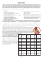
MATERIALS. Any type of wood may be used
in your furnace, but specic varieties have
better energy yields than others. Please
consult the following table in order to make
the best possible choice.
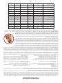
TYPE
WEIGHT
(LBS. CU. FT.,
DRY)
PER CORD
EFFICIENCY
RANKING
SPLITS
MILLIONS
BTU’s/CORD
Hickory 63 4500 1.0 Well 31.5
White Oak 48 4100 .9 Fair 28.6
Red Oak 46 3900 .8 Fair 27.4
Beech 45 3800 .7 Hard 26.8
Sugar
Maple
44 3700 .6 Fair 26.2
Black Oak 43 3700 .6 Fair 25.6
Ash 42 3600 .5 Well 25.0
Yellow
Birch
40 3400 .4 Hard 23.8
Red
Maple
38 3200 .3 Fair 22.6
Paper
Birch
37 3100 .3 Easy 22.1
Elm/
Sycamore
34 2900 .2
Very
Difcult
20.1
Red
Spruce
29 1800 .1 Easy 16.1

-20-
It is EXTREMELY IMPORTANT that you use DRY WOOD only. The wood should have dried for 9 to 15 months, such
that the humidity content (in weight) is reduced below 20% of the weight of the log. It is very important to keep
in mind that even if the wood has been cut for one, two or even more years, it is not necessarily dry, if it has
been stored in poor conditions. Under extreme conditions it may rot, instead of drying. This point cannot be over
stressed; the vast majority of the problems related to the operation of a wood furnace is caused by the fact that
the wood used was too damp or has dried in poor conditions.
These problems can be:
• Ignition problems
• Creosote build-up causing chimney res
• Low energy yield
• Blackened windows
• Incomplete log combustion
Smaller pieces of wood will dry faster. All logs exceeding 6” in diameter should be split. The wood should not be
stored directly on the ground. Air should circulate through the cord. A 24” to 48” air space should be left between
each row of logs, which should be placed in the sunniest location possible. The upper layer of wood should be
protected from the elements but not the sides.
NOTICE: To minimize the risk of smoke spillage when opening the door with a re in your furnace, crack
the door open no more than 1” and wait for at least 10 seconds before opening it more to allow pressure
stabilization inside the furnace.
TESTING YOUR WOOD
When the furnace is thoroughly warmed, place one piece of split wood (about ve inches in diameter) parallel
to the door on the bed of red embers.
Adjust all air controls to there maximum settings and close the door. If ignition of the piece is accomplished
within 90 seconds from the time if was placed in the furnace, your wood is correctly dried. If ignition takes longer,
your wood is damp.
If your wood hisses and water or vapor escapes at the ends of the piece, your wood is soaked or freshly cut.
Do not use this wood in your furnace. Large amounts of creosote could be deposited in your chimney, creating
potential conditions for a chimney re.
THE FIRST FIRES
The fresh paint on your furnace needs to be cured to preserve its quality. Once the fuel charge is properly
ignited, only burn small res in your furnace for the rst four hours of operation. Never open the air control’s more
than necessary to achieve a medium burn rate.
Make sure that there’s enough air circulation while curing the furnace. DO NOT connect your furnace to the
duct work during this curing process. The odors could be smelled during the 3 or 4 rst res. Never start your
furnace outside. You will not be able to see if you are over heating.
LIGHTING YOUR WOOD FURNACE
1. Make sure that your furnace has been installed as per the instructions outlined in this manual and the proper
power is supplied to it.
2. Open the fuel loading door.
3. Note: If there already is a bed of hot/glowing coals in the combustion chamber, proceed directly to the
Preheating step.
4. Place several pieces of small dry kindling in the front of the combustion chamber directly on the rebricks.
5. Lay a few twists of newspaper over the kindling.
6. Lay more dry kindling (crisscrossing) on top of the previous layers and possibly a few more twists of newspaper
if needed.
7. Light the lowest newspaper in the stack.
Note: In some draft situation you may be required to leave the door cracked no more than ½” only till a re is
established in the stack
No chemical product should be used to light the re.
PREHEATING YOUR WOOD FURNACE
1. Once the kindling is burning well or the glowing coal bed is stirred up, lay 2 or 3 pieces of well-seasoned
cordwood down so that the flame from the kindling re can circulate around the logs and close the door.
Note: You may need to add more kindling to help ignite the cordwood.
2. Before loading your furnace fully you will want a well-established re in the combustion chamber. This
typically takes 15-20 minutes.
La page est en cours de chargement...
La page est en cours de chargement...
La page est en cours de chargement...
La page est en cours de chargement...
La page est en cours de chargement...
La page est en cours de chargement...
La page est en cours de chargement...
La page est en cours de chargement...
La page est en cours de chargement...
La page est en cours de chargement...
La page est en cours de chargement...
La page est en cours de chargement...
La page est en cours de chargement...
La page est en cours de chargement...
La page est en cours de chargement...
La page est en cours de chargement...
La page est en cours de chargement...
La page est en cours de chargement...
La page est en cours de chargement...
La page est en cours de chargement...
La page est en cours de chargement...
La page est en cours de chargement...
La page est en cours de chargement...
La page est en cours de chargement...
La page est en cours de chargement...
La page est en cours de chargement...
La page est en cours de chargement...
La page est en cours de chargement...
La page est en cours de chargement...
La page est en cours de chargement...
La page est en cours de chargement...
La page est en cours de chargement...
La page est en cours de chargement...
La page est en cours de chargement...
La page est en cours de chargement...
La page est en cours de chargement...
La page est en cours de chargement...
La page est en cours de chargement...
La page est en cours de chargement...
La page est en cours de chargement...
-
 1
1
-
 2
2
-
 3
3
-
 4
4
-
 5
5
-
 6
6
-
 7
7
-
 8
8
-
 9
9
-
 10
10
-
 11
11
-
 12
12
-
 13
13
-
 14
14
-
 15
15
-
 16
16
-
 17
17
-
 18
18
-
 19
19
-
 20
20
-
 21
21
-
 22
22
-
 23
23
-
 24
24
-
 25
25
-
 26
26
-
 27
27
-
 28
28
-
 29
29
-
 30
30
-
 31
31
-
 32
32
-
 33
33
-
 34
34
-
 35
35
-
 36
36
-
 37
37
-
 38
38
-
 39
39
-
 40
40
-
 41
41
-
 42
42
-
 43
43
-
 44
44
-
 45
45
-
 46
46
-
 47
47
-
 48
48
-
 49
49
-
 50
50
-
 51
51
-
 52
52
-
 53
53
-
 54
54
-
 55
55
-
 56
56
-
 57
57
-
 58
58
-
 59
59
-
 60
60


Ashley AF1500E Le manuel du propriétaire
- Catégorie
- Poêles
- Taper
- Le manuel du propriétaire
dans d''autres langues
- English: Ashley AF1500E Owner's manual
Documents connexes
Autres documents
-
United States Stove AW40E Le manuel du propriétaire
-
US Stove Company US2941EB Le manuel du propriétaire
-
-
USSC AF1600E Mode d'emploi
-
United States Stove Company HB1520 Le manuel du propriétaire
-
Ashley Hearth Products AF1600E Le manuel du propriétaire
-
-
 Hotblast 1500 Le manuel du propriétaire
-
United States Stove VG900 Le manuel du propriétaire
-
Quadra-Fire CASTILE-MBK Manuel utilisateur
