United States Stove Company HB1520 Le manuel du propriétaire
- Catégorie
- Poêles
- Taper
- Le manuel du propriétaire

* All Pictures In This Manual Are For Illustrative Purposes Only. Actual Product May Vary.
© 2023 United States Stove Company, 227 Industrial Park Rd., South Pittsburg, TN 37380 Ph. 800-750-2723
THIS MANUAL IS SUBJECT TO CHANGE WITHOUT NOTICE.
Owner’s Instruction and Operation Manual
SAFETY NOTICE: If this unit is not properly installed, a fire may result. For your
safety, follow the installation instructions. Never use make-shift compromises during
the installation of this unit. Contact local building or fire ocials about permits,
restrictions and installation requirements in your area.
CAUTION! Please read this entire manual before you install or use this unit. Failure
to follow instructions may result in property damage, bodily injury, or even death.
Improper Installation Will Void Your Warranty!
Save These Instructions In A Safe Place For Future Reference.
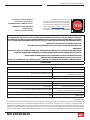
CALIFORNIA PROPOSITION 65 WARNING:
This product can expose you to chemicals including carbon
monoxide, which is known to the State of California to cause
cancer, birth defects, and/or other reproductive harm. For
more information, go to www.P65warnings.ca.gov
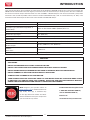
U.S. Environmental Protection Agency
Certified to comply with 2020 particulate
emission standards
HB1520
Model Number:
Wood Only Central Furnace
R
Certified to UL-391-2006 (R2019), Certified
to: CSA B366.1-11 (R2020), and CSA B415.1:22
Report Number: 22-808
853966D- 0406M

2
© 2023 United States Stove Company
INTRODUCTION
For Customer Service, please call:
1-800-750-2723 Ext 5050 or;
Text to 423-301-5624 or;
Email us at:
customerservice@usstove.com
Note: Register your product online at
www.usstove.com or download the free
app today. This app is available only
on the App Store for iPhone and iPad.
Search US Stove. Save your receipt with
your records for any claims.
CAUTIONS:
• HOT WHILE IN OPERATION. KEEP CHILDREN, CLOTHING AND FURNITURE AWAY. CONTACT MAY CAUSE
SKIN BURNS.
• DO NOT USE CHEMICALS OR FLUIDS TO IGNITE THE FIRE.
• DO NOT LEAVE THE STOVE UNATTENDED WHEN THE DOOR IS SLIGHTLY OPENED.
• DO NOT BURN GARBAGE, FLAMMABLE FLUID SUCH AS GASOLINE, NAPHTHA OR MOTOR OIL.
• DO NOT CONNECT TO ANY AIR DISTRIBUTION DUCT OR SYSTEM.
• ALWAYS CLOSE THE DOOR AFTER THE IGNITION.
• YOUR CHIMNEY MUST BE INSPECTED PRIOR TO THE INSTALLATION OF YOUR NEW WOOD STOVE.
IN ADDITION, YOU SHOULD HAVE YOUR CHIMNEY INSPECTED FOR CREOSOTE DEPOSTS MONTHLY
DURING THE HEATING SEASON AND ANNUALLY INSPECTED AND CLEANED.
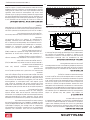
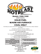
This manual describes the installation and operation of the Hotblast, HB1520 wood furnace. This furnace meets the
2020 U.S. Environmental Protection Agency’s emission limits for wood furnaces. Under specific EPA test conditions
this furnace has been shown to deliver heat at a rate of 15,997 – 53,042 BTU/hr. This furnace achieved a particulate
emissions rate of 0.13 lb/mmBtu when tested to method CSA B415.1-10 (*and an overall eciency of 70%). The
maximum overall heat output of this furnace was tested to be 65,258 Btu/hr.
Combustible: Wood
Flue Pipe Diameter: 6” (153cm)
Flue Pipe Type: (Standard, Single Wall, or
Double Wall): Black or Blued Steel 2100°F (650°C) Class “A”
Minimum Chimney Height: 12 ft (3.65 m)
Maximum Log Length: 23” (585 mm)
Electrical: 120 Volts, 60 Hz, 6.0 Amps
Dimensions
Assembled Height x Width x Depth: 45” (1143 mm) x 25-3/8” (645 mm) x 54-3/4” (1391 mm)
Combustion Chamber:
Width x Depth: 13.75” (350 mm) x 24” (610 mm)
Volume:
Cubic Feet: 3.95 Cu Ft.
Door Opening: Width x Height: 14” (356 mm) x 13.89” (353 mm)

© 2023 United States Stove Company
3
INSTALLATION CHECKLIST
Your Wood Stove should be installed by a qualified installer only. An NFI qualified Installer can be found at;
www.nficertified.org/public/find-an-nfi-pro/
CUSTOMER SERVICE
1-800-750-2723 ext 5050
Text to 423-301-5624
Email to: Customerservice@usstove.com
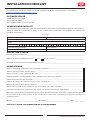
COMMISSIONING CHECKLIST
This checklist is to be completed in full by the qualified person who installs this unit. Keep this page for future reference.
Failure to install and commission according to the manufacturer’s instructions and complete this checklist will
invalidate the warranty.
Please Print
Customer Name: Telephone Number:
Address:
Model:
Serial Number:
Installation Company Name: Phone Number:
Installation Technician’s Name: License Number:
DESCRIPTION OF WORK
Location of installed appliance: __________________________________________________________________________________
Chimney System: New Chimney System Yes No If yes, Brand _________________________________________
If no, Date of inspection of the existing chimney system: __________________________________________________________
COMMISSIONING
Confirm Hearth Pad Installation as per Installation Instructions ...................................................................................................
Confirm proper placement of internal parts ..........................................................................................................................................
Check soundness of door gasket and door seals .................................................................................................................................
Confirm clearances to combustibles as per installation instructions in this manual ..............................................................
Check the operations of the air controls .................................................................................................................................................
Confirm all flue pipe and chimney system are secure and sealed ..................................................................................................
Confirm the stove properly drafts when fired .......................................................................................................................................
Check to ensure a CO alarm is installed as per local building codes and is functional ............................................................
Explain the safe operation, proper fuel usage, cleaning and routine maintenance requirements ........................................
Declaration of Completion: As the qualified person responsible for the work described above, I confirm that the appliance
as associated work has been installed as per manufacturer’s instructions and following any applicable building and
installation codes.
Signed: ______________________________________ Print Name: __________________________________Date: ______________
Home Owner: RETAIN THIS INFORMATION FOR FUTURE REFERENCE

4
© 2023 United States Stove Company
ASSEMBLY INSTRUCTIONS
TOOLS AND MATERIALS
The following is a list of tools and materials needed to
install your furnace.
• Safety glasses and gloves
• Various Hand Tools for component assembly. (Power
tools preferably)
• All Chimney and Chimney Connector materials required
for your particular installation.
• Electrical wiring tools and supplies
• All materials needed for Ductwork Installation (Supply
and return air) (Return Air Box is supplied with the unit)
UNPACKING
1. Remove all packaging from the furnace.
2. Remove the supplied parts from the furnace.
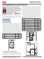
FIREBRICK CONFIGURATION
Inspect for any damage. Ensure that the bricks and
ash plug are positioned correctly and not broken (see
illustration for proper brick arrangement). NOTE: The
firebricks are silicone into place to prevent damage from
shipping. Attempting to remove the firebricks before
operation could result in damage.
CERAMIC FIBER BOARD CONFIGURATION
Inspect for any damage. Ensure the fiber board is
positioned correctly and not broken (see illustration for
proper fiber board arrangement). NOTE: The ceramic
fiber boards are silicone into place to prevent damage
from shipping. Attempting to remove the ceramic fiber
board before operation could result in damage.
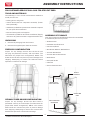
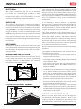
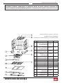
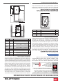
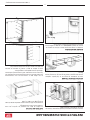
ASSEMBLY OF FURNACE
Your furnace requires the following items to be assembled
or installed by the service person:
• Smoke Curtain
• Feed Door Handle & Latch
• Front Cover/Hood
• Distribution Blowers With Gaskets
• Junction Box Bracket
• Junction Box and Fan Center
• Draft Blower
• Honeywell Probe
• Filter Box
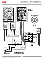
• Electrical Connections
JUNCTION
BOX
DISTRIBUTION
BLOWERS
HONEYWELL
LIMIT SWITCH
DRAFT
BLOWER
FOR CUSTOMER SERVICE CALL: 8007502723 EXT 5050

© 2023 United States Stove Company
5
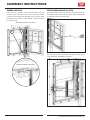
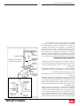
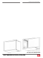
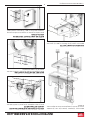
SMOKE CURTAIN
Using two (2) 1/4-20 x 1-1/4” Carriage bolts, two (2)
smoke curtain clips, and two (2) nuts, attach the smoke
curtain in place above the fuel feed door as shown. After
installation, the smoke curtain should swing freely back
into the furnace.
OUTSIDE VIEW OF THE UNIT
INSIDE VIEW OF THE UNIT
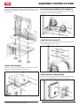
FEED DOOR HANDLE & LATCH
Use the included one (1) nut and one (1) washer to secure
the handle to the stove as shown. Note: Adjust the handle
as needed to ensure a proper seal.
Use two (2) 1/4-20 x 3/4 bolts and two (2) washers to
secure the latch assembly to the unit.
ASSEMBLY INSTRUCTIONS

6
© 2023 United States Stove Company
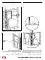
ASSEMBLY INSTRUCTIONS
Use three (3) 1/4-20 x 3/4 bolts, three (3) washers, and
three (3) 1/4-20 kep nuts to secure the latch top to the
latch bottom.
FRONT COVER/HOOD
Use the four (4) provided #10A x 1/2 screws to secure
the front cover hood to the unit as shown.
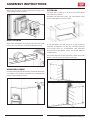
DISTRIBUTION BLOWERS WITH GASKETS
Secure the two blowers and gaskets to the unit using the
eight (8) provided 1/4-20 x 3/4 bolts.
JUNCTION BOX BRACKET
Secure the junction box bracket to the unit using the four
(4) provided #10A x 1/2 screws.
JUNCTION BOX & FAN CENTER
Secure the junction box to the junction box bracket using
the two (2) provided #10A x 1/2 screws as shown.

© 2023 United States Stove Company
7
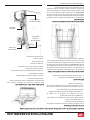
Secure the fan center to the junction box using the two
(2) provided screws as shown.
DRAFT BLOWER
Secure the draft blower to the back upper left-hand side
of the unit using the four (4) provided 10-24 kep nuts.
HONEYWELL PROBE
Install the Honeywell probe into the ducktwork above the
unit. NOTE: The conduit is supplied at a predetermined
length of approximately 3 feet
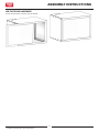
FILTER BOX
The filter box is made up of 4 parts, plus all hardware
necessary for assembly.
Assemble the filter box sides, top, and bottom using
twenty (20) #10 A x 1/2 HX screws.
If your BX Cables will not match up to the previously
matched arrangement on the top, carefully measure
and custom notch to accommodate your particular
arrangement of BX Cables. There are several dierent
configurations.
Secure the filter box to the unit using a total of ten (10)
#10 A x 1/2 HX screws, five (5) on each side.
ASSEMBLY INSTRUCTIONS

8
© 2023 United States Stove Company
AIR FILTER REPLACEMENT
Insert one 16 x 24 x 1 air filter (not included).
ASSEMBLY INSTRUCTIONS

© 2023 United States Stove Company
9
INSTALLATION
ATTENTION:
• FAILURE TO FOLLOW THE INFORMATION IN
THIS MANUAL WILL CAUSE A HAZARD THAT
COULD RESULT IN DEATH, SERIOUS BODILY
INJURY, AND/OR PROPERTY DAMAGE.
• CHECK YOUR LOCAL CODES. THE INSTALL ATION
MUST COMPLY WITH THEIR RULINGS.
• ALWAYS CONNECT THIS FURNACE TO A
CHIMNEY AND VENT TO THE OUTSIDE. NEVER
VENT TO ANOTHER ROOM OR INSIDE A
BUILDING.
• DO NOT CONNECT THIS FURNACE TO AN
ALUMINUM TYPE B GAS VENT. THIS IS NOT
SAFE AND IS PROHIBITED BY THE NATIONAL
FIRE PROTECTION ASSOCIATION CODE. THIS
FURNACE REQUIRES A MASONRY OR LISTED
FACTORY BUILT CHIMNEY FOR RESIDENTIAL
TYPE OR BUILDING HEATING APPLIANCE
CHIMNEY. USE A 6" DIAMETER CHIMNEY OR
LARGER, THAT IS HIGH ENOUGH TO GIVE A
GOOD DRAFT.
• INSPECT CHIMNEY CONNECTOR AND
CHIMNEY BEFORE AND FREQUENTLY DURING
THE HEATING SEASON FOR ANY DEPOSIT
OF CREOSOTE OR SOOT WHICH MUST BE
REMOVED.
• PROVIDE AIR FOR COMBUSTION INTO THE
ROOM WHERE THE FURNACE IS LOCATED. IF
THE INTAKE IS NOT IN THE SAME ROOM, AIR
MUST HAVE FREE ACCESS TO THE ROOM.
• CAST IRON PARTS MUST BE "SEASONED" TO
AVOID CRACKING, BUILD ONLY SMALL FIRES
ON FIRST USE.
• TO PREVENT INJURY, DO NOT ALLOW ANYONE
TO USE THIS FURNACE WHO IS UNFAMILIAR
WITH THE CORRECT OPERATION OF THE
FURNACE.
CAUTION
GASES THAT ARE DRIVEN FROM FRESH WOOD
MUST BE BURNED OR THEY WILL ACCUMULATE
AND EXPLODE. NEVER SMOTHER A FIRE WHEN
ADDING FRESH WOOD.
DANGER: RISK OF FIRE OR EXPLOSION.
DO NOT BURN GARBAGE, GASOLINE, DRAIN OIL,
OR OTHER FLAMMABLE LIQUIDS.
WARNING: FIRE HAZARD.
• DO NOT OPERATE WITH FIRE DRAFT
EXCEEDING 0.06" W.C.
• DO NOT STORE FUELS, PAINTS, THINNERS,
FLAMMABLE LIQUIDS, OR OTHER HIGHLY
VOLATILE SUBSTANCES IN THE FURNACE
ROOM.
CAUTION!
CLEANOUT OF THE COMBUSTION CHAMBER,
FLUE PIPE, AND CHIMNEY IS ESPECIALLY
IMPORTANT AT THE END OF THE HEATING
SEASON TO MINIMIZE CORROSION DURING
THE SUMMER MONTHS CAUSED BY MOISTURE
ACCUMULATING IN LEFT-OVER ASH.
CAUTION!
INSPECT FLUE PIPES, FLUE PIPE JOINTS AND
FLUE PIPE SEALS REGULARLY TO ENSURE THAT
SMOKE AND FLUE GASES ARE NOT DRAWN INTO,
AND CIRCULATED BY, THE AIR CIRCULATION
SYSTEM.
SAFETY NOTICE:
IF THIS FURNACE IS NOT PROPERLY INSTALLED,
A HOUSE FIRE MAY RESULT. FOR YOUR SAFETY,
FOLLOW THE INSTALLATION DIRECTIONS.
CONTACT LOCAL BUILDING OR FIRE OFFICIALS
ABOUT RESTRICTIONS AND INSTALLATION
INSPECTION REQUIREMENTS IN YOUR AREA.
IF NOT ALREADY INSTALLED, WE RECOMMEND
THAT SMOKE DETECTORS BE INSTALLED.
CAUTION:
HOT SURFACES! KEEP CHILDREN AWAY. DO NOT
TOUCH DURING OPERATION.

10
© 2023 United States Stove Company
US Stove highly recommends your stove be installed by a
qualified NFI (US) or WETT (Canada) technician. To find
the nearest qualified installer, go to:
https://nficertified.org,
https://www.wettinc.ca/
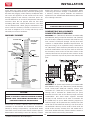
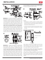
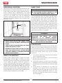
FLOOR PROTECTOR
The furnace must be placed on solid concrete, solid
masonry, or when installed on a combustible floor, on a
floor protector. The floor protector is required to provide
heat, live ember, and ash protection and must be of a non-
combustible, continuous solid surface to protect against
infiltration of live embers and ash. Floor protection must
have and R-Value of at least 1.4. Refer to floor protector
manufacturer’s instructions for installation directions.
The floor protector or non combustible floor must extend
under the furnace and beyond each side as shown below.
Dimension Inch mm
AFront 24 609.6
B Flue Rear 2 50.8
C Side 8 203.2
A
C
C
B
FLUE
CLEARANCES TO COMBUSTIBLES
The installation of this furnace includes supplying
electrical power, return air ductwork, and supply air
ductwork. This furnace may be installed as a stand alone
wood furnace only. See installation section in this manual
to ensure proper assembly, installation and operation
of your new furnace. If installing in an area with a fan it
should not be allowed to create negative pressure in the
room where the furnace is installed. When locating your
furnace ensure the required maintenance clearances are
maintained. Your furnace must be installed as shown in
this manual and in compliance with all local and national
codes. It is of the utmost importance that the clearances
to combustible materials be strictly adhered to during
installation of the furnace. Refer to the table and diagrams
below for minimum required clearances.
Dimension Inch mm
D Backwall To Furnace 26 661
E Sidewall To Furnace 16 407
F Sidewall To Flue 25 635
G Backwall To Flue 18 458
H Supply Duct (first 6 feet) 6 153
J Supply Duct (after first 6 feet) 2 51
K Minimum Duct Height 8 204
L Top Of Door To Ceiling 48 1220
M Minimum Ceiling Height 75 1905
Back wall
Side wall
Side wall
F
E
D
Ceiling
Floor Protector
H (First 6ft)
J
K
L
M
G
INSTALLATION
FOR CUSTOMER SERVICE CALL: 8007502723 EXT 5050FOR CUSTOMER SERVICE CALL: 8007502723 EXT 5050

© 2023 United States Stove Company
11
DUCT WORK
We strongly recommend that the hot air ductwork
be installed by a home heating specialist. If doing
the installation yourself, consult a qualified heating
technician and follow his recommendations as to the
safest and most ecient method of installation.
SUPPLY AIR
The supply air duct shall be constructed of metal in
accordance with NFPA 90B, 2-1.1. The plenums installed
to the furnace shall be constructed of metal in accordance
with NFPA 90B, 2-1.3. When installing this furnace the
supply air plenum is to have a minimum height of 24”
(610mm) if the top of the first vertical section is not flush
with the top of the first horizontal section of ductwork.
If the top of the plenum is flush with the top of the first
horizontal section of ductwork then the minium height is
15” (381mm).
RETURN AIR
The return air intake on the furnace is on the rear of the
unit. The ductwork must be mechanically attached to the
unit or blower box with sheet metal screws to ensure a
proper operation.
STAND ALONE INSTALLATION
When installing this stand alone furnace, ensure all local
codes and all instructions in this manual are followed,
including clearance to combustibles, floor protector
specifications and safety warnings.
20.5
28.5
Supply Air Duct Work Outlet Size
LISTED FACTORY BUILT CHIMNEY
Your wood furnace may be hooked up with a factory
built or masonry chimney, matching the diameter of the
exhaust. If you are using a factory built chimney, it must
comply with UL 103 or CSA-B365 standard; therefore it
must be a Type HT (2100°F). It is extremely important
that it be installed according to the manufacturer’s
specifications.
If you are using a masonry chimney, it is important
that it be built in compliance with the specifications of
the National Building Code. It must be lined with fire
clay bricks, metal or clay tiles sealed together with fire
cement. (Round flues are the most ecient).
The interior diameter of the chimney flue must be
identical to the furnace smoke exhaust. A flue which is
too small may cause draft problems, while a large flue
favors rapid cooling of the gas, and hence the build-up
of creosote and the risk of chimney fires. Note that it is
the chimney and not the furnace which creates the draft
eect; your furnace’s performance is directly dependent
on an adequate draft from your chimney.
Do not connect this unit to a chimney flue serving another
appliance.
The following recommendations may be useful for the
installation of your chimney:
• It must rise above the roof at least 3’ (0.9m) from the
uppermost point of contact.
• The exterior portion should be double or triple wall pipe
to ensure proper draft.
• The chimney must exceed any part of the building or
other obstruction within a 10’ (3.04m) distance by a
height of 2’ (0.6m).
• Installation of an interior chimney is always preferable
to an exterior chimney. The interior chimney will be
hotter than an exterior chimney that is being cooled
by the ambient air outside the house. Therefore the
gas which circulates will cool slower, thus reducing the
build-up of creosote and the risk of chimney fires.
• The draft caused by the tendency for hot air to rise will
be increased with an interior chimney.
• Using a fire screen at the extremity of the chimney
requires regular inspection in order to ensure that it is
not obstructed thus blocking the draft, and it should be
cleaned when used regularly.
IMPORTANCE OF PROPER DRAFT
Draft is the force which moves air from the appliance
up through the chimney. The amount of draft in your
chimney depends on the length of the chimney, local
geography, nearby obstructions and other factors. Too
INSTALLATION

12
© 2023 United States Stove Company
INSTALLATION
much draft may cause excessive temperatures in the
appliance. Inadequate draft may cause back pung into
the room and ‘plugging’ of the chimney. Inadequate draft
will cause the appliance to leak smoke into the room
through appliance and chimney connector joints. An
uncontrollable burn or excessive temperature indicates
excessive draft. Do not operate with the flue draft
exceeding .06 water column/14.93 Pascals. The draft
can be checked with a draft gauge or manometer. Take
into account the chimney’s location to ensure it is not
too close to neighbors or in a valley which may cause
unhealthy or nuisance conditions.
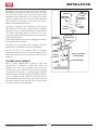
MASONRY CHIMNEY
Sheathing
Airtight
Cleanout
Door
Floor
Protector
Thimble
12” of Brick
Combustible Wall
1” Clearance
with Firestop
Rafter
Concrete Cap
Flashing
To Stove
1” Clearance
Eave
Flashing
Fireclay Flue
Liner With
Airspace
CAUTION:
BE SURE THAT IF A MASONRY CHIMNEY IS
USED, IT IS SAFELY CONSTRUCTED AND IN GOOD
REPAIR. HAVE THE CHIMNEY INSPECTED BY THE
FIRE DEPARTMENT OR AN INSPECTOR.
Ensure that a masonry chimney meets the minimum
standards of the National Fire Protection Association
(NFPA) by having it inspected by a professional. Make
sure there are no cracks, loose mortar or other signs of
deterioration and blockage. Have the chimney cleaned
before the furnace is installed and operated. When
connecting the furnace through a combustible wall to
a masonry chimney, special methods are needed as
explained in the “Combustible Wall Chimney Connector
Pass-Throughs” Section.
WARNING:
DO NOT CONNECT THIS FURNACE TO A CHIMNEY
FLUE SERVING ANOTHER APPLIANCE.
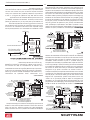
COMBUSTIBLE WALL CHIMNEY
CONNECTOR PASSTHROUGHS
METHOD A - 12” (304.8 mm) Clearance to Combustible
Wall Member: Using a minimum thickness 3.5” (89 mm)
brick and a 5/8” (15.9 mm) minimum wall thickness clay
liner, construct a wall pass-through. The clay liner must
conform to ASTM C315 (Standard Specification for
Clay Fire Linings) or its equivalent. Keep a minimum of
12” (304.8 mm) of brick masonry between the clay liner
and wall combustibles. The clay liner shall run from the
brick masonry outer surface to the inner surface of the
chimney flue liner but not past the inner surface. Firmly
grout or cement the clay liner in place to the chimney flue
liner.
METHOD B - 9” (228.6 mm) Clearance to Combustible
Wall Member: Using a 6” (152.4 mm) inside diameter,
listed, factory-built Solid-Pak chimney section with
insulation of 1” (25.4 mm) or more, build a wall pass-
through with a minimum 9” (228.6 mm) air space
between the outer wall of the chimney length and wall
combustibles. Use sheet metal supports fastened
securely to wall surfaces on all sides, to maintain the
9” (228.6 mm) air space. When fastening supports to
chimney length, do not penetrate the chimney liner (the
inside wall of the Solid-Pak chimney). The inner end of
the Solid-Pak chimney section shall be flush with the
inside of the masonry chimney flue, and sealed with a
non-water soluble refractory cement. Use this cement to
also seal to the brick masonry penetration.

© 2023 United States Stove Company
13
METHOD C - 6” (152.4 mm) Clearance to Combustible
Wall Member: Starting with a minimum 24 gage (.024”
[.61 mm]) 6” (152.4 mm) metal chimney connector, and
a minimum 24 gage ventilated wall thimble which has
two air channels of 1” (25.4 mm) each, construct a wall
pass-through. There shall be a minimum 6” (152.4 mm)
separation area containing fiberglass insulation, from the
outer surface of the wall thimble to wall combustibles.
Support the wall thimble, and cover its opening with a
24-gage minimum sheet metal support. Maintain the 6”
(152.4 mm) space. There should also be a support sized
to fit and hold the metal chimney connector. See that
the supports are fastened securely to wall surfaces on
all sides. Make sure fasteners used to secure the metal
chimney connector do not penetrate chimney flue liner.
METHOD D - 2” (50.8 mm) Clearance to Combustible
Wall Member: Start with a solid-pak listed factory
built chimney section at least 12” (304 mm) long, with
insulation of 1” (25.4 mm) or more, and an inside diameter
of 8” (2 inches [51 mm] larger than the 6” [152.4 mm]
chimney connector). Use this as a pass-through for a
minimum 24-gauge single wall steel chimney connector.
Keep solid-pak section concentric with and spaced 1”
(25.4 mm) o the chimney connector by way of sheet
metal support plates at both ends of chimney section.
Cover opening with and support chimney section on both
sides with 24 gage minimum sheet metal supports. See
that the supports are fastened securely to wall surfaces
on all sides. Make sure fasteners used to secure chimney
flue line do not penetrate the inner liner.
NOTES:
• Connectors to a masonry chimney, excepting method
B, shall extend in one continuous section through the
wall pass-through system and the chimney wall, to but
not past the inner flue liner face.
• A chimney connector shall not pass through an attic or
roof space, closet or similar concealed space, or a floor,
or ceiling.
CHIMNEY CONNECTOR
3 screws
Flow
Direction
of Flue
Gases
Install
crimped
end
towards
stove.
Male Part Downwards
1/4” slope per foot
Your chimney connector and chimney must have the
same diameter as the furnace outlet. If this is not the
case, we recommend you contact your dealer in order to
ensure there will be no problem with the draft.
The furnace pipe must be made of aluminized or cold roll
steel with a minimum thickness of 0.021” or 0.53 mm. It
is strictly forbidden to use galvanized steel.
Your connector should be assembled in such a way that
the male section (crimped end) of the pipe faces down.
Attach each of the sections to one another with three
equidistant metal screws. Seal the joints with furnace
cement.
INSTALLATION

14
© 2023 United States Stove Company
INSTALLATION
The pipe must be short and straight. All sections installed
horizontally must slope at least 1/4 inch per foot, with
the upper end of the section toward the chimney. Any
installation with a horizontal run of furnace pipe must
conform to NFPA 211. You may contact NFPA (National
Fire Protection Association) and request the latest
edition of the NFPA Standard 211.
To ensure a good draft, the total length of the furnace
pipe should never exceed 8’ to 10’ (2.4m to 3.04 m).
(Except for cases of vertical installation, cathedral-roof
style where the smoke exhaust system can be much
longer and connected without problem to the chimney at
the ceiling of the room).
There should never be more than two 90 degrees elbows
in the smoke exhaust system.
Installation of a “barometric draft stabilizer” (fireplace
register) on a smoke exhaust system is prohibited.
Do not use with a flue damper. With a controlled
combustion wood furnaces the draft is regulated upon
intake of the combustion air in the furnace and not at the
exhaust.
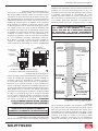
FACTORY BUILT CHIMNEY
When a metal prefabricated chimney is used, the
manufacturer’s installation instructions must be
followed. You must also purchase (from the same
manufacturer) and install the ceiling support package
or wall pass-through and “T” section package, firestops
(where needed), insulation shield, roof flashing, chimney
cap, etc. Maintain proper clearance to the structure as
recommended by the manufacturer. The chimney must be
the required height above the roof or other obstructions
for safety and proper draft operation.
Listed Cap
Maintain 2”
Clearance
Listed
Chimney
Ceiling
Support
Ceiling
Support
Chimney
Connector
** Refer to Clearance
to Combustibles
Combustible Wall
Floor
Protector
To Stove
Storm Collar
Flashing
Listed
Chimney Attic
Insulation
Sheild
Specified
Clearance
Chimney
Connector
Combustible
Ceiling Joists
To Stove

© 2023 United States Stove Company
15
OPERATION
NEVER OPERATE THIS PRODUCT WHILE UNATTENDED
CAUTIONS: HOUSE FIRE HAZARDS
• DO NOT STORE WOOD ON FLOOR PROTECTOR,
UNDERNEATH STOVEPIPE(S) OR ANYWHERE
WITHIN CLEARANCES TO COMBUSTIBLE
SURFACES SPECIFIED FOR THIS APPLIANCE.
• NEVER OPERATE WITH SECONDARY TUBES,
FIBERBOARD, OR INSULATION REMOVED.
OPERATING SAFETY PRECAUTIONS
• NEVER OVERFIRE THIS APPLIANCE BY
BUILDING EXCESSIVELY HOT FIRES AS A
HOUSE/BUILDING FIRE MAY RESULT. YOU ARE
OVERFIRING THE APPLIANCE IF IT BEGINS TO
GLOW OR TURN RED.
• NEVER BUILD EXCESSIVELY LARGE FIRES IN
THIS TYPE OF APPLIANCE AS DAMAGE TO THE
FIREBOX OR SMOKE LEAKAGE MAY RESULT.
• DO NOT BUILD FIRE TOO CLOSE TO THE GLASS.
• HOT WHILE IN OPERATION. KEEP CHILDREN,
CLOTHING, AND FURNITURE AWAY. CONTACT
MAY CAUSE SKIN BURNS. DO NOT TOUCH THE
APPLIANCE UNTIL IT HAS COOLED.
• PROVIDE ADEQUATE AIR FOR COMBUSTION
TO THE ROOM WHERE THE APPLIANCE IS
INSTALLED.
• INSPECT CHIMNEY LINER EVERY 60 DAYS.
REPLACE LINER IMMEDIATELY IF IT IS RUSTING
OR LEAKING SMOKE INTO THE ROOM.
• ATTEMPTS TO ACHIEVE HEAT OUTPUT
RATES THAT EXCEED FURNACE DESIGN
SPECIFICATIONS CAN RESULT IN PERMANENT
DAMAGE TO THE FURNACE.
WARNING: EXPLOSION HAZARD
• NEVER USE CHEMICALS, GASOLINE, GASOLINE-
TYPE LANTERN FUEL, KEROSENE, CHARCOAL
LIGHTER FLUID, OR SIMILAR FLAMMABLE
LIQUIDS TO START OR “FRESHEN UP” A FIRE IN
THE APPLIANCE.
• KEEP ALL FLAMMABLE LIQUIDS, ESPECIALLY
GASOLINE, OUT OF THE VICINITY OF THE
APPLIANCE - WHETHER IN USE OR IN STORAGE.
Your heating appliance was designed to burn well
seasoned natural wood only; no other materials should
be burned. Any type of well seasoned natural wood
may be used in your stove, but specific varieties have
better energy yields than others. Higher eciencies and
lower emissions generally result when burning air dried
seasoned hardwoods, as compared to softwoods or too
green or freshly cut hardwoods. The following resources
can assist in learning the burn characteristics of various
species of wood:
http://firewoodresource.com/firewood-btu-ratings/; or
https://forestry.usu.edu/forest-products/wood-heating
The operation of this wood furnace in a manner
inconsistent with the owner’s manual will void your
warranty and is also against federal regulations. Waste
and other flammable materials should not be burned in
your stove. DO NOT BURN:
1. Garbage;
2. Lawn clippings or yard waste;
3. Materials containing rubber, including tires;
4. Materials containing plastic;
5. Waste petroleum products, paints or paint thinners,
or asphalt products;
6. Materials containing asbestos;
7. Construction or demolition debris;
8. Railroad ties or pressure-treated wood;
9. Manure or animal remains;
10. Saltwater driftwood or other previously salt water-
saturated materials;
11. Unseasoned wood; or
12. Paper products, cardboard, plywood, or particleboard.
The prohibition against burning these materials does
not prohibit the use of fire starters made from paper,
cardboard, sawdust, wax, and similar substances to
start a fire in an aected wood furnace.
Burning these materials may result in the release of toxic
fumes or render the furnace ineective and cause smoke.
Deadwood lying on the forest floor should be considered
wet and requires full seasoning time. Standing deadwood
can usually be considered to be about 2/3 seasoned.
Smaller pieces of wood will dry faster. All logs exceeding
6” in diameter should be split. The wood should not be
stored directly on the ground. Air should circulate through
the logs. A 24” to 48” air space should be left between
each row of logs, which should be placed in the sunniest
location possible. The upper layer of wood should be
protected from the element but not the sides. A good
indicator of if the wood is ready to burn is to check the

16
© 2023 United States Stove Company
piece ends. If cracks are radiating in all directions from
the center then the wood should be dry enough to burn.
If your wood sizzles in the fire, even though the surface
is dry, it may not be fully cured and should be seasoned
longer. It is EXTREMELY IMPORTANT that you use DRY
WOOD only in your wood stove. The wood should have
dried for 9 to 15 months, such that the humidity content
(in weight) is reduced below 20% of the weight of the log.
It is very important to keep in mind that even if the wood
has been cut for one, two, or even more years, it is not
necessarily dry, if it has been stored in poor conditions.
Under extreme conditions, it may rot instead of drying.
This point cannot be overstressed; the vast majority of
the problems related to the operation of a wood stove is
caused by the fact that the wood used was too damp or
had dried in poor conditions. These problems can be:
• ignition problems
• creosote build-up causing chimney fires
• low energy yield
• blackened windows
• incomplete log combustion
Do not burn manufactured logs made of wax
impregnated sawdust or logs with any chemical
additives.
TESTING YOUR WOOD
• When the furnace is thoroughly warmed, place one
piece of split wood (about five inches in diameter)
parallel to the door on the bed of red embers.
• Adjust all air controls to there maximum settings and
close the door. If ignition of the piece is accomplished
within 90 seconds from the time if was placed in the
furnace, your wood is correctly dried. If ignition takes
longer, your wood is damp.
If your wood hisses and water or vapor escapes at
the ends of the piece, your wood is soaked or freshly
cut (green). Do not use this wood in your stove. Large
amounts of creosote could be deposited in your chimney,
creating potential conditions for a chimney fire.
POWER FAILURE
DO NOT add additional fuel after a power failure, remove
all air filters and reduce combustion air to a minimum.
Observe furnace closely until power is restored.
TAMPER WARNING
This wood furnace has a manufacturer-set minimum low
burn rate that must not be altered. It is against federal
regulations to alter this setting or otherwise operate this
wood furnace in a manner inconsistent with operating
instructions in this manual.
EFFICIENCIES
Eciencies can be based on either the lower heating
value (LHV) or the higher heating value (HHV) of the
fuel. The lower heating value is when water leaves the
combustion process as a vapor, in the case of woodstoves
the moisture in the wood being burned leaves the stove
as a vapor. The higher heating value is when water leaves
the combustion process completely condensed. In the
case of woodstoves this would assume the exhaust gases
are room temperature when leaving the system, and
therefore calculations using this heating value consider
the heat going up the chimney as lost energy. Therefore,
eciency calculated using the lower heating value of
wood will be higher than eciency calculated using the
higher heating value. The best way to achieve optimum
eciencies is to learn the burn characteristic of you
appliance and burn well-seasoned wood. Higher burn
rates are not always the best heating burn rates; after a
good fire is established a lower burn rate may be a better
option for ecient heating. A lower burn rate slows the
flow of usable heat out of the home through the chimney,
and it also consumes less wood.
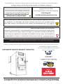
NOTICE INITIAL BURNS TO CURE PAINT
BECAUSE OF THE HIGH OPERATING TEMPERATURES,
THIS APPLIANCE IS COATED WITH A SPECIAL HIGH
TEMP PAINT WHICH REQUIRES A SERIES OF LOW TO
MEDIUM BURNS TO FULLY CURE FOR DURABILITY
AND A LIFETIME OF SERVICE.
Proper curing of the high-temp paint requires a series of
three initial burns. The appliance should be allowed to
cool o between each burn. The first two burns should
be small fires and low temperatures (250°F) for a
duration of 20 minutes each. The third fire should be at
a temperature of approximately 500°F for 20 minutes.
Provide adequate cross ventilation to clear any smoke or
odor caused by initial firings.
Notice: Use solid wood fuel only! Do not burn garbage,
or flammable fluids. Do not use coal. This appliance
is not designed to accommodate the air flow (draft)
required to properly burn coal or coal products. Do
not elevate the fire using grates or irons. Build the fire
directly on the firebrick.
FUELING INSTRUCTIONS
To ensure this unit produces the optimal minimum
emissions it is critical that only well-seasoned cordwood
is burned. Burning unseasoned wet wood only hurts
OPERATION

© 2023 United States Stove Company
17
your stoves eciency and leads to accelerated
creosote buildup in your chimney. Be considerate of the
environment and only burn dry wood.
CAUTION:
DO NOT LEAVE APPLIANCE UNATTENDED WITH
THE DOOR OPEN.
WARNINGS:
• NEVER OVERFIRE YOUR STOVE. IF ANY PART
OF THE STOVE STARTS TO GLOW RED, OVER
FIRING IS HAPPENING. READJUST THE AIR
INTAKE CONTROL AT A LOWER SETTING.
• THE INSTALLATION OF A LOG CRADLE OR
GRATES IS NOT RECOMMENDED IN YOUR WOOD
STOVE. BUILD FIRE DIRECTLY ON FIREBRICK.
• NEVER PUT WOOD ABOVE THE FIREBRICK
LINING OF THE FIREBOX.
• ATTEMPTS TO ACHIEVE HEAT OUTPUT
RATES THAT EXCEED FURNACE DESIGN
SPECIFICATIONS CAN RESULT IN PERMANENT
DAMAGE TO THE FURNACE.
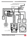
GENERAL FURNACE OPERATION
Honeywell Limit Control
This device, mounted in the ductwork, just above the air
discharge atop the furnace, works in conjunction with
a wall thermostat, operating the distribution blowers
and the combustion fan on the rear of the furnace. The
factory settings are 100/150/200. The wall thermostat
setting operates the ON time of the combustion fan. If the
temperature is below the setting on the wall thermostat,
the combustion fan will come ON. (Recommended
setting at 5 to 10 degrees higher than other heating
thermostats.) The first two set points on the limit control
operates the distribution blowers. When the furnace
plenum temperature reaches the second set point on the
limit control, the distribution blowers will come on. If the
temperature falls to the first set point, the distribution
blower will shut-o. When the furnace reaches the
third set point on the limit control, the combustion fan
will shut-o. Once the temperature falls below that set
point and the wall thermostat is still calling for heat, the
combustion fan will turn back ON. The 200° is a Factory
Preset Limit for the combustion fan and should never
be changed. Doing so could result in excessive firebox
temperatures and could permanently damage your
firebox.
FURNACE LOADING PROCEDURE
Starting your Furnace
• When lighting the furnace, the wall thermostat should
be set to its MAX setting so that the combustion fan is
ON. Start the fire with approximately 12 lbs. of kindling,
which will be several small strips of wood, 1-1/2 to
2-1/2 inches wide, approximately 12 to 15 inches deep
in the bottom of the firebox. Leave the fuel loading door
slightly open to ensure good ignition of the kindling.
Make sure the combustion fan is ON and its damper is
closed, then pull the knob/loop on the front of the unit
to prop open the barometric dampers.
• Once the kindling is fully ignited, add another 12 to 15
lbs. of kindling, which will be around the same amount
as the initial load.
• Leave the door slightly open for three to five minutes
(3-5 min) to ensure full ignition of the second kindling
load.
• After the second load of kindling is fully ignited, you
can close the door and push the knob/loop on the front
of the unit back in to allow the barometric dampers to
function freely. After 15 minutes, fully open the damper
on the combustion fan.
• Once the kindling burns down to about 8 lbs., which
should be to the point that the kindling will break up
into a full bed of coals, the preload can be added into
the firebox. The preload should consist of around 40
pounds of properly seasoned cord wood, which should
be about 6 to 8 pieces of wood.
• After loading the preload, close the door, and make
certain the combustion fan is ON.
• Allow about one hour (1hr) for the preload to burn down
to around 10-12 lbs. or when all the preload wood will
break up into coals. You should now have a coal bed
that is several inches deep in the bottom of the firebox.
• The purpose of the preload burn is to establish a proper
coal bed prior to inserting the main load of wood. Having
a proper coal bed is the key to a complete ignition of
the main wood load and to maintain the correct firebox
temperatures to get the best emissions and eciency
output of the furnace.
• After you have completed the preload burn, you may
insert your main firewood load.
• The main load should be the same size or amount as
the preload, approximately 40 pounds of cord wood, 6
to 8 pieces.
• Try to keep gaps between the pieces of wood to help
with the ignition and maintain a good fire.
OPERATION

18
© 2023 United States Stove Company
MAIN FIREWOOD LOAD
• Ensure that the combustion fan is ON, and open the
feed door to insert the main firewood load.
• After loading, leave the feed door slightly open for five
minutes (5 min) to ensure proper ignition, then close
the door.
• The damper on the combustion fan should be open.
• Depending on the temperature at which the wall
thermostat is set, this will determine the burn duration
of the main load. A lower setting on the thermostat
should result in a longer burn time as this would allow
the combustion fan to remain OFF for longer periods.
A higher thermostat setting will cycle the combustion
blower ON/OFF more often, resulting in a hotter, but
shorter duration burn time of course. However, colder
outside temperatures and your home’s construction
(insulation) will play a big factor in how well the
thermostat can maintain it’s set temperature.
VISIBLE SMOKE
The amount of visible smoke being produced can be
an eective method of determining how eciently the
combustion process is taking place at the given settings.
Visible smoke consist of unburned fuel and moisture
leaving your stove. Learn to adjust the air settings of your
specific unit to produce the smallest amount of visible
smoke. Wood that has not been seasoned properly and
has a high wood moisture content will produce excess
visible smoke and burn poorly. Use the included moisture
meter to ensure your wood has a 20% or less moisture
content.
AIR TUBES
The air tubes assembled in this unit are designed to
provide an accurate mix of secondary air to ensure the
highest eciency. Any damage or deterioration of these
tubes may reduce the eciency of combustion. The air
tubes are held in position by screws or snap pins. Locate
these to either side of the tube and remove it to allow the
tube to be removed and replaced.
OPERATION

© 2023 United States Stove Company
19
MAINTENANCE
CAUTION:
DO NOT OVERFIRE APPLIANCE. YOU ARE
OVERFIRING IF ANY PART OF THE APPLIANCE
GLOWS RED. CLOSE THE DOOR AND SHUT DAMPER
IMMEDIATELY TO REDUCE THE AIR SUPPLY AND
SLOW DOWN THE FIRE.
CAUTION:
SLOW BURNING FIRES FOR EXTENDED USE OR
BURNING GREEN WOOD MAY CAUSE EXCESSIVE
CREOSOTE BUILD-UP. IGNITION OF CREOSOTE
OR OVERFIRING COULD CAUSE A CHIMNEY
FIRE. CHIMNEY FIRES BURN EXTREMELY HOT
AND MAY IGNITE SURROUNDING COMBUSTIBLE
MATERIALS. IN CASE OF A CHIMNEY FIRE, CALL
THE FIRE DEPARTMENT IMMEDIATELY!
CREOSOTE & SOOT FORMATION & NEED
FOR REMOVAL
When wood is burned slowly, the products of combustion
combine with moisture to form a soot residue which
accumulates on the flue lining. When ignited, this soot
makes an extremely hot fire. The chimney should be
inspected at least twice monthly during the heating
season to determine if a creosote or soot build up
has occurred. If creosote or soot has accumulated, it
should be removed to reduce the risk of a chimney fire.
Chimney fires burn very hot. If the chimney catches fire,
immediately call the fire department, then reduce the fire
by closing the inlet air control. Pour a large quantity of
coarse salt, baking soda or cool ashes on top of the fire in
the firebox.
CREOSOTE ACCUMULATION CAUSES CHIMNEY
FIRES. YOU SHOULD CHECK (OR HAVE CHECKED BY
A QUALIFIED CHIMNEY SWEEP) YOUR CHIMNEY FOR
CREOSOTE DEPOSITS AT LEAST MONTHLY DURING
THE HEATING SEASON. ANY ACCUMULATIONS
SHOULD BE REMOVED. COMPLETE CHIMNEY
INSPECTIONS AND CLEANING SHOULD BE
CONDUCTED ANNUALLY; TYPICALLY, THIS TASK
SHOULD BE PERFORMED PRIOR TO EACH HEATING
SEASON. IF USING AN EXISTING CHIMNEY, IT MUST
BE INSPECTED PRIOR TO THE INSTALLATION OF
YOUR NEW WOOD STOVE.
CAUTION
A CHIMNEY FIRE MAY CAUSE IGNITION OF WALL
STUDS OR RAFTERS WHICH YOU THOUGHT WERE
A SAFE DISTANCE FROM THE CHIMNEY. IF YOU
HAVE A CHIMNEY FIRE, HAVE YOUR CHIMNEY
INSPECTED BY A QUALIFIED PERSON BEFORE
USING AGAIN.
ATTENTION:
THIS FURNACE NEEDS PERIODIC INSPECTION AND
REPAIR FOR PROPER OPERATION. IT IS AGAINST
FEDERAL REGULATIONS TO OPERATE THIS
FURNACE IN A MANNER INCONSISTENT WITH
OPERATING INSTRUCTIONS IN THIS MANUAL.
TO PREVENT CREOSOTE BUILD UP
• Always burn dry wood. This allows clean burns and
higher chimney temperatures, therefore less creosote
deposit.
• Always check for creosote deposit once every two
months and have your chimney cleaned at least once
a year.
• If a chimney or creosote fire occurs, close all dampers
immediately. Wait for the fire to go out and the furnace
to cool, then inspect the chimney for damage. If no
damage results, perform a chimney cleaning to ensure
no more creosote deposits is remaining in the chimney.
CAUTION:
A CHIMNEY FIRE MAY CAUSE IGNITION OF WALL
STUDS OR RAFTERS WHICH WERE ASSUMED TO
BE A SAFE DISTANCE AWAY FROM THE CHIMNEY.
IF A CHIMNEY FIRE OCCURS, HAVE YOUR
CHIMNEY INSPECTED BY A QUALIFIED EXPERT
BEFORE USING AGAIN.
NEVER OPERATE THIS PRODUCT WHILE UNATTENDED

20
© 2023 United States Stove Company
ASH REMOVAL & DISPOSAL
Never let your ashes get any higher than the pilot air hole.
Remove ashes as needed leaving at least 2 inches of ash
in the bottom of the firebox. Ashes should be placed in
a metal container with a tight-fitting lid. The closed
container of ashes should be placed on a noncombustible
floor or on the ground, away from all combustible
materials, pending final disposal. The ashes should be
retained in the closed container until all cinders have
thoroughly cooled.
PILOT AIR
OPENINGS
CAUTIONS:
• ASHES COULD CONTAIN HOT EMBERS EVEN
AFTER TWO DAYS WITHOUT OPERATING THE
STOVE.
• THE ASH PAN CAN BECOME VERY HOT. WEAR
GLOVES TO PREVENT INJURY.
• NEVER BURN THE STOVE WITH THE ASH TRAP
OPEN. THIS WOULD RESULT IN OVER FIRING
THE STOVE. DAMAGE TO THE STOVE AND EVEN
HOUSE FIRE MAY RESULT.
SMOKE & CO MONITORS
Burning wood naturally produces smoke and carbon
monoxide(CO) emissions. CO is a poisonous gas when
exposed to elevated concentrations for extended periods
of time. While the modern combustion systems in
furnaces drastically reduce the amount of CO emitted
out the chimney, exposure to the gases in closed or
confined areas can be dangerous. Make sure you stove
gaskets and chimney joints are in good working order
and sealing properly to ensure unintended exposure. It is
recommended that you use both smoke and CO monitors
in areas having the potential to generate CO.
GASKET CARE
WARNING:
NEVER OPERATE THE STOVE WITHOUT GASKETS
OR WITH BROKEN GASKETS. DAMAGE TO THE
STOVE OR EVEN HOUSE FIRE MAY RESULT.
It is recommended that you change the door gasket
(which makes your furnace door air tight) once a year,
in order to ensure good control over the combustion,
maximum eciency and security. To change the door
gasket, simply remove the damaged one. Carefully clean
the available gasket groove, apply a high temperature
silicone sold for this purpose and install the new gasket.
You may light up your furnace again approximately 24
hours after having completed this operation. This unit’s
feed door uses a 5/8” diameter rope gasket. The door
glass on this unit uses a 1 x 1/8 gasket.
ATTENTION:
THIS WOOD FURNACE NEEDS PERIODIC
INSPECTION AND REPAIR FOR PROPER
OPERATION. IT IS AGAINST FEDERAL
REGULATIONS TO OPERATE THIS WOOD FURNACE
IN A MANNER INCONSISTENT WITH OPERATING
INSTRUCTIONS IN THIS MANUAL.
SERVICE HINTS
Do not expect a furnace to draw. It is the chimney that
creates the draft. Smoke spillage into the house or
excessive build-up of water or creosote in the chimney
are warnings that the chimney is not functioning properly.
Correct the problem before using furnace. Possible
causes are:
1. The connector pipe may be pushed into the chimney
too far, stopping the draft.
2. Do not connect two furnaces or a stove and furnace
into the same chimney flue.
3. The chimney used for a furnace must not be used to
ventilate the cellar or basement. If there is a cleanout
opening at the base of the chimney, it must be closed
tightly.
4. If the chimney is operating too cool, water will
condense in the chimney and run back into the
furnace. Creosote formation will be rapid and may
block the chimney. Operate the furnace at a high
enough fire to keep the chimney warm, preventing
this condensation.
MAINTENANCE
La page est en cours de chargement...
La page est en cours de chargement...
La page est en cours de chargement...
La page est en cours de chargement...
La page est en cours de chargement...
La page est en cours de chargement...
La page est en cours de chargement...
La page est en cours de chargement...
La page est en cours de chargement...
La page est en cours de chargement...
La page est en cours de chargement...
La page est en cours de chargement...
La page est en cours de chargement...
La page est en cours de chargement...
La page est en cours de chargement...
La page est en cours de chargement...
La page est en cours de chargement...
La page est en cours de chargement...
La page est en cours de chargement...
La page est en cours de chargement...
La page est en cours de chargement...
La page est en cours de chargement...
La page est en cours de chargement...
La page est en cours de chargement...
La page est en cours de chargement...
La page est en cours de chargement...
La page est en cours de chargement...
La page est en cours de chargement...
La page est en cours de chargement...
La page est en cours de chargement...
La page est en cours de chargement...
La page est en cours de chargement...
-
 1
1
-
 2
2
-
 3
3
-
 4
4
-
 5
5
-
 6
6
-
 7
7
-
 8
8
-
 9
9
-
 10
10
-
 11
11
-
 12
12
-
 13
13
-
 14
14
-
 15
15
-
 16
16
-
 17
17
-
 18
18
-
 19
19
-
 20
20
-
 21
21
-
 22
22
-
 23
23
-
 24
24
-
 25
25
-
 26
26
-
 27
27
-
 28
28
-
 29
29
-
 30
30
-
 31
31
-
 32
32
-
 33
33
-
 34
34
-
 35
35
-
 36
36
-
 37
37
-
 38
38
-
 39
39
-
 40
40
-
 41
41
-
 42
42
-
 43
43
-
 44
44
-
 45
45
-
 46
46
-
 47
47
-
 48
48
-
 49
49
-
 50
50
-
 51
51
-
 52
52


United States Stove Company HB1520 Le manuel du propriétaire
- Catégorie
- Poêles
- Taper
- Le manuel du propriétaire
dans d''autres langues
Documents connexes
-
Ashley Hearth Products AF1300E Le manuel du propriétaire
-
-
Ashley AF1500E Le manuel du propriétaire
-
United States Stove VG900 Le manuel du propriétaire
-
 Hotblast 1500 Le manuel du propriétaire
-
United States Stove 2016EB Le manuel du propriétaire
-
-
USSC TR001B Le manuel du propriétaire
-
