
KERN & Sohn GmbH
Tel: +49-[0]7433- 9933-0
Fax: +49-[0]7433-9933-149
Internet: www.kern-sohn.com
Installationsanleitung
Assembly instructions
Istructions d’installation
KERN SXC, IXC
Typ
Type
Type
TSXC-A01-A
TIXC-A01-A
TIXC-A02-A
Version 1.0
2023-06
TSXC-A01-A_TIXC-A01-A_TIXC-A02-A-IA-def-2310


TSXC-A01-A_TIXC-A01-A_TIXC-A02-A-IA-def-2310 1
Deutsch
D
Stative
Version 1.0 2023-06
Installationsanleitung
Inhaltsverzeichnis
1 Technische Daten .......................................................................................... 2
1.1 Abmessungen ........................................................................................................................... 2
2 Lieferumfang .................................................................................................. 5
3 Installation ...................................................................................................... 6

2 TSXC-A01-A_TIXC-A01-A_TIXC-A02-A-IA-def-2310
Deutsch
1 Technische Daten
KERN
TSXC-A01-A
TIXC-A01-A
TIXC-A02-A
Stativhöhe (mm)
330
330
600
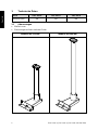
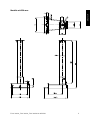
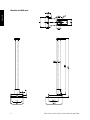
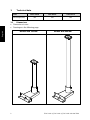
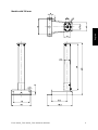
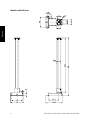
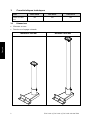
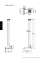
1.1 Abmessungen
• Maße in mm
• Zeichnungen auf der nächsten Seite
Modelle mit 330 mm
Modelle mit 600 mm

TSXC-A01-A_TIXC-A01-A_TIXC-A02-A-IA-def-2310 3
Deutsch
Modelle mit 330 mm:

4 TSXC-A01-A_TIXC-A01-A_TIXC-A02-A-IA-def-2310
Deutsch
Modelle mit 600 mm:

TSXC-A01-A_TIXC-A01-A_TIXC-A02-A-IA-def-2310 5
Deutsch
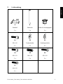
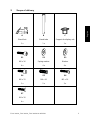
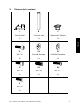
2 Lieferumfang
A
B
C
Stativfuß
Stativrohr
Halter für Anzeigegerät
1 x
1 x
1 x
S1
S2
S3
M6 x 16
Federscheibe
Unterlegscheibe
4 x
4 x
4 x
S4
S5
S6
M6 x 12
M6 x 10
M5 x 16
1 x
2 x
3 x
S7
M4 x 10
4 x

6 TSXC-A01-A_TIXC-A01-A_TIXC-A02-A-IA-def-2310
Deutsch
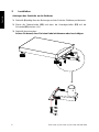
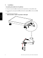
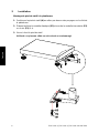
3 Installation
Anbringen des Stativfußs an die Plattform:
1. Stativfuß (A) mittig über den Bohrungen auf der Seite der Plattform positionieren.
2. Zuerst die Federscheibe (S2) und dann die Unterlegscheibe (S3) auf die
Schraube (S1) stecken (4 x).
3. Stativfuß festschrauben.
Achten Sie darauf, dass Sie keine Kabel einklemmen oder beschädigen.

TSXC-A01-A_TIXC-A01-A_TIXC-A02-A-IA-def-2310 7
Deutsch
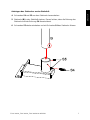
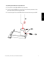
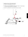
Anbringen des Stativrohrs an den Stativfuß:
4. Schrauben S4 und S5 aus dem Stativrohr herausdrehen.
5. Stativrohr (B) in den Stativfuß stecken. Darauf achten, dass die Bohrung des
Stativrohrs mit der Bohrung S4 übereinstimmt.
6. Schrauben S5 wieder eindrehen und mit Schraube S4 das Stativrohr fixieren.

8 TSXC-A01-A_TIXC-A01-A_TIXC-A02-A-IA-def-2310
Deutsch
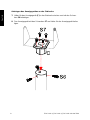
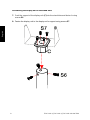
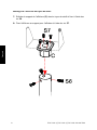
Anbringen des Anzeigegerätes an das Stativrohr:
7. Halter für das Anzeigegerät (C) in das Stativrohr stecken und mit den Schrau-
ben S6 befestigen.
8. Das Anzeigegerät mit den Schrauben S7 am Halter für das Anzeigegerät befes-
tigen.

TSXC-A01-A_TIXC-A01-A_TIXC-A02-A-IA-def-2310 1
English
GB
Stands
Version 1.0 2023-06
Installation Instructions
Contents
1 Technical data ................................................................................................ 2
1.1 Dimensions ............................................................................................................................... 2
2 Scope of delivery ........................................................................................... 5
3 Installation ...................................................................................................... 6

2 TSXC-A01-A_TIXC-A01-A_TIXC-A02-A-IA-def-2310
English
1 Technical data
KERN
TSXC-A01-A
TIXC-A01-A
TIXC-A02-A
Stand height (mm)
330
330
600
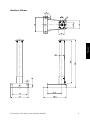
1.1 Dimensions
• Dimensions in mm
• Drawings on the following page
Models with 330 mm
Models with 600 mm

TSXC-A01-A_TIXC-A01-A_TIXC-A02-A-IA-def-2310 3
English
Models with 330 mm:

4 TSXC-A01-A_TIXC-A01-A_TIXC-A02-A-IA-def-2310
English
Models with 600 mm:

TSXC-A01-A_TIXC-A01-A_TIXC-A02-A-IA-def-2310 5
English
2 Scope of delivery
A
B
C
Stand foot
Stand tube
Support for display unit
1 x
1 x
1 x
S1
S2
S3
M6 x 16
Spring washer
Washer
4 x
4 x
4 x
S4
S5
S6
M6 x 12
M6 x 10
M5 x 16
1 x
2 x
3 x
S7
M4 x 10
4 x

6 TSXC-A01-A_TIXC-A01-A_TIXC-A02-A-IA-def-2310
English
3 Installation
Assembling the stand foot to the platform:
1. Place the stand foot (A) centrically over the perforations on the platform side.
2. First plug the spring washer (S2) and then the washer (S3) on the screw (S1)
(4 x).
3. Screw down the stand foot.
Make sure that no cables are jammed or damaged.

TSXC-A01-A_TIXC-A01-A_TIXC-A02-A-IA-def-2310 7
English
Assembling the stand tube to the stand foot:
4. Unscrew the screws S4 and S5 from the stand tube.
5. Push the stand tube (B) into the stand foot. Ensure that the perforation of the
stand tube matches with the perforation S4.
6. Screw down again the screws S5 and fasten the stand tube using screw S4.

8 TSXC-A01-A_TIXC-A01-A_TIXC-A02-A-IA-def-2310
English
Assembling the display unit to the stand tube:
7. Push the support of the display unit (C) into the stand tube and fasten it using
screws S6.
8. Fasten the display unit to the display unit’s support using screws S7.

TSXC-A01-A_TIXC-A01-A_TIXC-A02-A-IA-def-2310 1
Français
F
Statifs
Version 1.0 2023-06
Notice d'installation
Table des matières
1 Caractéristiques techniques ......................................................................... 2
1.1 Dimensions ............................................................................................................................... 2
2 Etendue de la livraison .................................................................................. 5
3 Installation ...................................................................................................... 6

2 TSXC-A01-A_TIXC-A01-A_TIXC-A02-A-IA-def-2310
Français
1 Caractéristiques techniques
KERN
TSXC-A01-A
TIXC-A01-A
TIXC-A02-A
Hauteur du statif
(mm)
330
330
600
1.1 Dimensions
• Mesures en mm
• Dessins sur la page suivante
Modèles à 330 mm
Modèles à 600 mm
La page est en cours de chargement...
La page est en cours de chargement...
La page est en cours de chargement...
La page est en cours de chargement...
La page est en cours de chargement...
La page est en cours de chargement...
-
 1
1
-
 2
2
-
 3
3
-
 4
4
-
 5
5
-
 6
6
-
 7
7
-
 8
8
-
 9
9
-
 10
10
-
 11
11
-
 12
12
-
 13
13
-
 14
14
-
 15
15
-
 16
16
-
 17
17
-
 18
18
-
 19
19
-
 20
20
-
 21
21
-
 22
22
-
 23
23
-
 24
24
-
 25
25
-
 26
26


KERN TIXC-A01-A Guide d'installation
- Taper
- Guide d'installation
- Ce manuel convient également à
dans d''autres langues
- English: KERN TIXC-A01-A Installation guide
- Deutsch: KERN TIXC-A01-A Installationsanleitung
Documents connexes
Autres documents
-
Danfoss ERC211 - A7 Format Guide d'installation
-
Sunny TM100 15-Level Auto Incline Treadmill Manuel utilisateur
-
Maxxus Crosstrainer CX 7.8 Manuel utilisateur
-
 SUNNY Health Fitness SF-T7705 Manuel utilisateur
-
-
-
